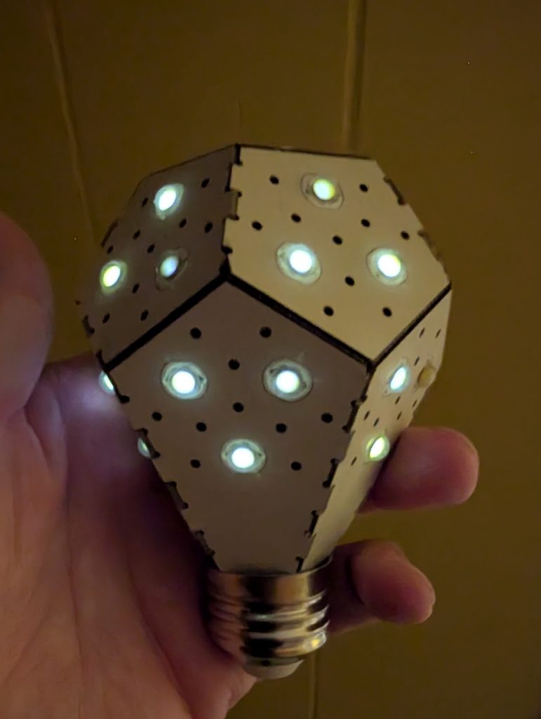
My NanoLeaf NanoLight LED bulb from 2013 finally gave up the ghost: or did it …?
woo! spooky glowing undead lightbulb!
The LEDs glowed for several minutes after removing it from the socket. I suspect capacitance is afoot.
Although it was absurdly expensive ($45 [USD?]; that’s about $62 with inflation) when I got it from the original Kickstarter campaign in 2013, it has been run for several hours a day since then. I always liked the shape of the bulb, with its origami-like folds.
Modern LED bulbs are much cheaper, but this one looks classy. The magic smoke has well and truly gone, and all that’s left is a faint glow and the stench of rancid phenolic.
Rather than use the Adafruit trade name, these are more properly called WS2812 LEDs. Each one contains a tiny microcontroller and it only takes three connections to drive a long chain of addressable colour LEDs. The downside is that the protocol to drive these is a bit of a bear, and really needs an accurate, fast clock signal to be reliable.
The STM32F411 chip does have just such a clock, and the generic micropython-ws2812 library slightly misuses the SPI bus to handle the signalling. The wiring’s simple:
F411 GND to WS2812 GND;
F411 3V3 to WS2812 5V;
F411 PA7 (SPI1_MOSI) PB15 (SPI2_MOSI) to WS2812 DIn
Next, copy ws2812.py into the WeAct F411’s flash. Now create a script to drive the LEDs. Here’s one to drive 8 LEDs, modified from the library’s advanced example:
# -*- coding: utf-8 -*-

import time
import math

from ws2812 import WS2812

ring = WS2812(spi_bus=2, led_count=8, intensity=0.1)

def data_generator(led_count):
    data = [(0, 0, 0) for i in range(led_count)]
    step = 0
    while True:
        red = int((1 + math.sin(step * 0.1324)) * 127)
        green = int((1 + math.sin(step * 0.1654)) * 127)
        blue = int((1 + math.sin(step * 0.1)) * 127)
        data[step % led_count] = (red, green, blue)
        yield data
        step += 1

for data in data_generator(ring.led_count):
    ring.show(data)
    time.sleep_ms(100)
Previously I said you’d see your WS2812s flicker and shimmer from the SPI bus noise. I thought it was cool, but I suspect it was also why the external flash on my F411 board just died. By pumping data into PA7, I was also hammering the flash chip’s DI line …
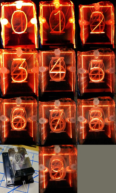
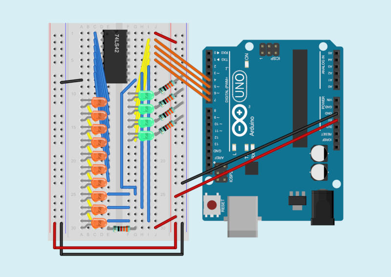
I want to make an edge-lit numeric display. These were a common technology before numeric LEDs were available. They use 10 illuminated slides to display individual numbers. Here’s my first try at the display:
The 74LS42 logic chip (4-Line BCD to 10-Line Decimal Decoder) seems a likely candidate to drive such a display. You feed it a 4-bit binary-coded decimal input, and the chip activates one of ten outputs. It’s a low-voltage version of the old 7441 chip used for driving Nixie tubes. Here’s what I got working as a demo of the 7442, driven by an Arduino:
Because the 7442 will only activate one output at a time, it’s okay to use a single current-limiting resistor for all ten output LEDs. The chip also uses active low outputs: the outputs go from high to low when activated. The negative side of each LED goes to an output pin, and the chip sinks current when an output is selected, lighting the LED.
The components get in the way of seeing the wiring, so here’s another picture from Fritzing with just the wires and the breadboard:
Finally, here’s the Arduino sketch I wrote to drive the chip for the demo video. All it does is cycle through digital outputs 4–7, incrementing a bit every half second.
/*
   SeventyfourFortytwo - Arduino demo of a
   74LS42 - 4-line BCD to 10-line decimal decoder
   Steps through 0-15, two steps per second
   Shows the 74LS42's blocking of values 10-15 as invalid

   Wiring:
   Arduino  74LS42
   ======== =======
    4      - 15  Input A (bit 0)
    5      - 14  Input B (bit 1)
    6      - 13  Input C (bit 2)
    7      - 12  Input D (bit 3)

   scruss - 2016-09-23
*/

int n = 0;

void setup() {
  pinMode(4, OUTPUT);
  pinMode(5, OUTPUT);
  pinMode(6, OUTPUT);
  pinMode(7, OUTPUT);
  digitalWrite(4, LOW);
  digitalWrite(5, LOW);
  digitalWrite(6, LOW);
  digitalWrite(7, LOW);
}

void loop() {
  digitalWrite(4, n & 1);
  digitalWrite(5, n & 2);
  digitalWrite(6, n & 4);
  digitalWrite(7, n & 8);
  n++;
  if (n > 15) n = 0;
  delay(500);
}
If you felt really fancy, you could drive the LED inputs through PWM, and come up with just the right of flicker to make this look like a Nixie tube. You should also be able to chain the inputs through some shift registers, too.
Update: I thought I’d work out this audio format some day. I haven’t yet, and since I no longer have the hardware, likely never will.
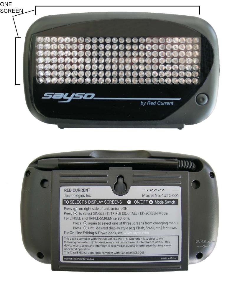
You may still be able to get Sayso Globord programmable LED signs in surplus stores. It’s a 7×24 LED scrolling sign that you can program with a lightpen or with audio input.
The unit comes with no software, but has a link to https://www.dropbox.com/sh/q1q9yhahwtblb23/AACpMeXQjYyD8ZWC-65vNgcxa printed on the box. (Link is still active in March 2026!). It’s an archive of the programming software, manual, and canned audio files for a whole bunch of standard messages. Here’s an archive if the dropbox link goes away: SaySo.zip
The audio files used for programming the display are clearly FSK-encoded, but I haven’t quite worked out the relationship between the tones and the display bits. Here’s what I’ve worked out so far:
Files are made up of 12 audio blocks, each about 0.9 seconds long. Each block appears to correspond to one 7×24 display screen.
Mark (1 bit): Three cycles, 96 samples at 44100 Hz: 1378.125 Hz
Space (0 bit): Four cycles, 256 samples at 44100 Hz: 689.0625 Hz
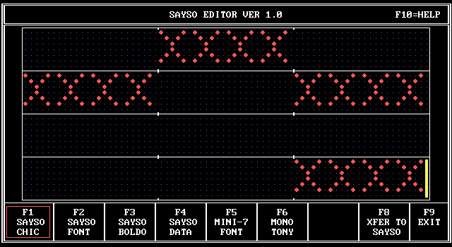
The editor runs nicely under DOSBox, so you can experiment and save samples as WAV files. Here’s a sample display with its corresponding audio linked underneath:
I’m not sure how much extra work I have time or inclination to put in on getting this working, but I hope that my preliminary work will be useful to someone (maybe this person).
Whoa! This is so old I don’t even know where to start!
It’s using Python 2, so if it works at all it probably won’t for much longer, and Tkinter is something completely different under Python 3
(grrreat planning there, Python guys …)
pyfirmata is likely ancient history too.
Phil sent me a note last week asking how to turn an LED on or off using Python talking through Firmata to an Arduino. This was harder than it looked.
It turns out the hard part is getting the value from the Tkinter Checkbutton itself. It seems that some widgets don’t return values directly, so you must read the widget’s value with a get() method. This appears to work:
#!/usr/bin/python
# turn an LED on/off with a Tk Checkbutton - scruss 2012/11/13
# Connection:
# - small LED connected from D3, through a resistor, to GND
import pyfirmata
from Tkinter import *
# Create a new board, specifying serial port
# board = pyfirmata.Arduino('/dev/ttyACM0') # Raspberry Pi
board = pyfirmata.Arduino('/dev/tty.usbmodem411') # Mac
root = Tk()
var = BooleanVar()
# set up pins
pin3 = board.get_pin('d:3:o') # D3 On/Off Output (LED)
def set_led(): # set LED on/off
ledval = var.get()
print "Toggled", ledval
pin3.write(ledval)
# now set up GUI
b = Checkbutton(root, text = "LED", command = set_led,
variable = var)
b.pack(anchor = CENTER)
root.mainloop()
Pretty much everyone tries the RGB colour cycler when they get their first Arduino. This variant cycles through the HSV colour wheel, though at fixed saturations and values.
Code:
// HSV fade/bounce for Arduino - scruss.com - 2010/09/12
// Note that there's some legacy code left in here which seems to do nothing
// but should do no harm ...

// don't futz with these, illicit sums later
#define RED       9 // pin for red LED
#define GREEN    10 // pin for green - never explicitly referenced
#define BLUE     11 // pin for blue - never explicitly referenced
#define SIZE    255
#define DELAY    10
#define HUE_MAX  6.0
#define HUE_DELTA 0.01

long deltas[3] = {
  5, 6, 7 };
long rgb[3];
long rgbval;
// for reasons unknown, if value !=0, the LED doesn't light. Hmm ...
// and saturation seems to be inverted
float hue=0.0, saturation=1.0, value=1.0;

/*
chosen LED SparkFun sku: COM-09264
 has Max Luminosity (RGB): (2800, 6500, 1200)mcd
 so we normalize them all to 1200 mcd -
 R  1200/2800  =  0.428571428571429   =   109/256
 G  1200/6500  =  0.184615384615385   =    47/256
 B  1200/1200  =  1.0                 =   256/256
 */
long bright[3] = {
  109, 47, 256};

long k, temp_value;

void setup () {
  randomSeed(analogRead(4));
  for (k=0; k<3; k++) {
    pinMode(RED + k, OUTPUT);
    rgb[k]=0;
    analogWrite(RED + k, rgb[k] * bright[k]/256);
    if (random(100) > 50) {
      deltas[k] = -1 * deltas[k]; // randomize direction
    }
  }
}

void loop() {
  hue += HUE_DELTA;
  if (hue > HUE_MAX) {
    hue=0.0;
  }
  rgbval=HSV_to_RGB(hue, saturation, value);
  rgb[0] = (rgbval & 0x00FF0000) >> 16; // there must be better ways
  rgb[1] = (rgbval & 0x0000FF00) >> 8;
  rgb[2] = rgbval & 0x000000FF;
  for (k=0; k<3; k++) { // for all three colours
    analogWrite(RED + k, rgb[k] * bright[k]/256);
  }
  delay(DELAY);
}

long HSV_to_RGB( float h, float s, float v ) {
  /* modified from Alvy Ray Smith's site: http://www.alvyray.com/Papers/hsv2rgb.htm */
  // H is given on [0, 6]. S and V are given on [0, 1].
  // RGB is returned as a 24-bit long #rrggbb
  int i;
  float m, n, f;

  // not very elegant way of dealing with out of range: return black
  if ((s<0.0) || (s>1.0) || (v<0.0) || (v>1.0)) {
    return 0L;
  }

  if ((h < 0.0) || (h > 6.0)) {
    return long( v * 255 ) + long( v * 255 ) * 256 + long( v * 255 ) * 65536;
  }
  i = floor(h);
  f = h - i;
  if ( !(i&1) ) {
    f = 1 - f; // if i is even
  }
  m = v * (1 - s);
  n = v * (1 - s * f);
  switch (i) {
  case 6:
  case 0:
    return long(v * 255 ) * 65536 + long( n * 255 ) * 256 + long( m * 255);
  case 1:
    return long(n * 255 ) * 65536 + long( v * 255 ) * 256 + long( m * 255);
  case 2:
    return long(m * 255 ) * 65536 + long( v * 255 ) * 256 + long( n * 255);
  case 3:
    return long(m * 255 ) * 65536 + long( n * 255 ) * 256 + long( v * 255);
  case 4:
    return long(n * 255 ) * 65536 + long( m * 255 ) * 256 + long( v * 255);
  case 5:
    return long(v * 255 ) * 65536 + long( m * 255 ) * 256 + long( n * 255);
  }
}
The PhotoSmart has an ability to print various ruled paper forms: lined, todo lists, and graph paper. But what they print for graph paper is merely squared paper:
Graph paper’s the stuff with 1mm squares. Personally, I was disappointed that it wouldn’t print log ruled and Smith charts, but that’s just me …
An ancient (even in 1985) Centronics serial dot-matrix printer that we never got working with the CPC464. The print head was driven along a rack, and when it hit the right margin, an idler gear was wedged in place, forcing the carriage to return. Crude, noisy but effective.
Amstrad DMP-2000. Plasticky but remarkably good 9-pin printer. Had an open-loop ribbon that we used to re-ink with thick oily endorsing ink until the ribbons wore through.
NEC Pinwriter P20. A potentially lovely 24-pin printer ruined by a design flaw. Print head pins would get caught in the ribbon, and snap off. It didn’t help that the dealer that sold it to me wouldn’t refund my money, and required gentle persuasion from a lawyer to do so.
Kodak-Diconix 300 inkjet printer. I got this to review for Amiga Computing, and the dealer never wanted it back. It used HP ThinkJet print gear which used tiny cartridges that sucked ink like no tomorrow; you could hear the droplets hit the page.
HP DeskJet 500. I got this for my MSc thesis. Approximately the shape of Torness nuclear power station (and only slightly smaller), last I heard it was still running.
Canon BJ 200. A little mono inkjet printer that ran to 360dpi, or 720 if you had all the time in the world and an unlimited ink budget.
Epson Stylus Colour. My first colour printer. It definitely couldn’t print photos very well.
HP LaserJet II. Big, heavy, slow, and crackling with ozone, this was retired from Glasgow University. Made the lights dim when it started to print. Came with a clone PostScript cartridge that turned it into the world’s second-slowest PS printer. We did all our Canadian visa paperwork on it.
Epson Stylus C80. This one could print photos tolerably well, but the cartridges dried out quickly, runing the quality and making it expensive to run.
Okidata OL-410e PS. The world’s slowest PostScript printer. Sold by someone on tortech who should’ve known better (and bought by someone who also should’ve known better), this printer jams on every sheet fed into it due to a damaged paper path. Unusually, it uses an LED imaging system instead of laser xerography, and has a weird open-hopper toner system that makes transporting a part-used print cartridge a hazard.
HP LaserJet 4M Plus. With its duplexer and extra paper tray it’s huge and heavy, but it still produces crisp pages after nearly 1,000,000 page impressions. I actually have two of these; one was bought for $99 refurbished, and the other (which doesn’t print nearly so well) was got on eBay for $45, including duplexer and 500-sheet tray. Combining the two (and judiciously adding a bunch of RAM) has given me a monster network printer which lets you know it’s running by dimming the lights from here to Etobicoke.
IBM Wheelwriter typewriter/ daisywheel printer. I’ve only ever produced a couple of pages on this, but this is the ultimate letter-quality printer. It also sounds like someone slowly machine-gunning the neighbourhood, so mostly lives under wraps.
HP PhotoSmart C5180. It’s a network photo printer/scanner that I bought yesterday. Really does print indistinguishably from photos, and prints direct from memory cards. When first installed, makes an amusing array of howls, boinks, squeals, beeps and sproings as it primes the print heads.
I’ve always thought that Adobe missed a great opportunity when they didn’t make their basic PDF writer freely available for Windows. Other OSs now have transparent print-to-PDF options. If you’re lucky, a corporate PC might have MS Office Document Image Writer installed, but a 300dpi monochrome TIFF can’t compare to a PDF.
Still, one can always install PDFCreator (if you have admin rights to the PC, of course). It’s a shame they decide to bundle a marginally dodgy toolbar/spyware package with it, but you don’t get that if you use the MSI installer package.
I reckon that if I took a random street poll anywhere (anywhere outside Canada, that is), no more than 3 out of 10 people would consider Canada as having a leadership role. I do not wish to make light of the soldiers’ plight; I just don’t want them there in my name.
(I was going to make a comment about the nearest thing to a role to most Canadians would be a Swiss Chalet 1/4 chicken dinner, but that doesn’t work in a written context, and barely works when spoken.)
Our tree is filled with Ruby-crowned Kinglets, and the title is Peterson’s poetic description of them. I guess they’re feeding up to migrate a bit south. Give news of yourselves when you bring spring back with you!
Got yet more mercury alloy trowelled into my head tonight by Dr Choi. I have to say, the best bit about going to the dentist is the squidgy noise the filling paste makes as it compresses into the cavity. It means it’s nearly over, and the burring slow drill is banished until next time.


 Phil sent me a note last week asking how to turn an LED on or off using Python talking through Firmata to an Arduino. This was harder than it looked.