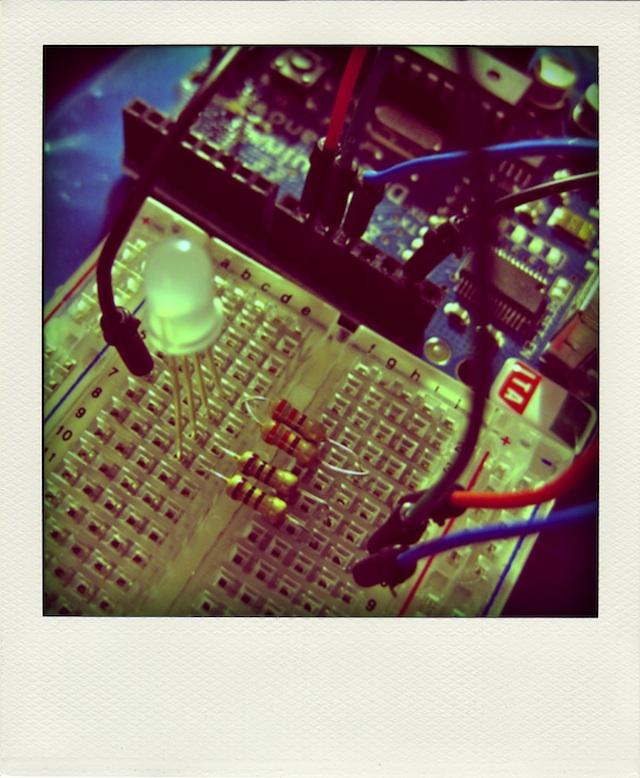
Pretty much everyone tries the RGB colour cycler when they get their first Arduino. This variant cycles through the HSV colour wheel, though at fixed saturations and values.
Code:
// HSV fade/bounce for Arduino - scruss.com - 2010/09/12
// Note that there's some legacy code left in here which seems to do nothing
// but should do no harm ...

// don't futz with these, illicit sums later
#define RED       9 // pin for red LED
#define GREEN    10 // pin for green - never explicitly referenced
#define BLUE     11 // pin for blue - never explicitly referenced
#define SIZE    255
#define DELAY    10
#define HUE_MAX  6.0
#define HUE_DELTA 0.01

long deltas[3] = {
  5, 6, 7 };
long rgb[3];
long rgbval;
// for reasons unknown, if value !=0, the LED doesn't light. Hmm ...
// and saturation seems to be inverted
float hue=0.0, saturation=1.0, value=1.0;

/*
chosen LED SparkFun sku: COM-09264
 has Max Luminosity (RGB): (2800, 6500, 1200)mcd
 so we normalize them all to 1200 mcd -
 R  1200/2800  =  0.428571428571429   =   109/256
 G  1200/6500  =  0.184615384615385   =    47/256
 B  1200/1200  =  1.0                 =   256/256
 */
long bright[3] = {
  109, 47, 256};

long k, temp_value;

void setup () {
  randomSeed(analogRead(4));
  for (k=0; k<3; k++) {
    pinMode(RED + k, OUTPUT);
    rgb[k]=0;
    analogWrite(RED + k, rgb[k] * bright[k]/256);
    if (random(100) > 50) {
      deltas[k] = -1 * deltas[k]; // randomize direction
    }
  }
}

void loop() {
  hue += HUE_DELTA;
  if (hue > HUE_MAX) {
    hue=0.0;
  }
  rgbval=HSV_to_RGB(hue, saturation, value);
  rgb[0] = (rgbval & 0x00FF0000) >> 16; // there must be better ways
  rgb[1] = (rgbval & 0x0000FF00) >> 8;
  rgb[2] = rgbval & 0x000000FF;
  for (k=0; k<3; k++) { // for all three colours
    analogWrite(RED + k, rgb[k] * bright[k]/256);
  }
  delay(DELAY);
}

long HSV_to_RGB( float h, float s, float v ) {
  /* modified from Alvy Ray Smith's site: http://www.alvyray.com/Papers/hsv2rgb.htm */
  // H is given on [0, 6]. S and V are given on [0, 1].
  // RGB is returned as a 24-bit long #rrggbb
  int i;
  float m, n, f;

  // not very elegant way of dealing with out of range: return black
  if ((s<0.0) || (s>1.0) || (v<0.0) || (v>1.0)) {
    return 0L;
  }

  if ((h < 0.0) || (h > 6.0)) {
    return long( v * 255 ) + long( v * 255 ) * 256 + long( v * 255 ) * 65536;
  }
  i = floor(h);
  f = h - i;
  if ( !(i&1) ) {
    f = 1 - f; // if i is even
  }
  m = v * (1 - s);
  n = v * (1 - s * f);
  switch (i) {
  case 6:
  case 0:
    return long(v * 255 ) * 65536 + long( n * 255 ) * 256 + long( m * 255);
  case 1:
    return long(n * 255 ) * 65536 + long( v * 255 ) * 256 + long( m * 255);
  case 2:
    return long(m * 255 ) * 65536 + long( v * 255 ) * 256 + long( n * 255);
  case 3:
    return long(m * 255 ) * 65536 + long( n * 255 ) * 256 + long( v * 255);
  case 4:
    return long(n * 255 ) * 65536 + long( m * 255 ) * 256 + long( v * 255);
  case 5:
    return long(v * 255 ) * 65536 + long( m * 255 ) * 256 + long( n * 255);
  }
}
- Digital pin 9 → 165Ω resistor → LED Red pin
- Digital pin 10 → 100Ω resistor → LED Green pin
- Digital pin 11 → 100Ω resistor → LED Blue pin
- GND → LED common cathode.
The different resistor values are to provide a limited current to the Triple Output LED RGB – Diffused, as each channel has different requirements. The 165Ω resistor is actually two 330Ω in parallel; I didn’t have the right value, and this was the closest I could make with what I had.

Hi,
Is that a bug in the code at line 70- where you return 0 if V is not = 1?
Looks that way, yes.
fixed line 70, I think.