Crickets in February

It’s mid-February in Toronto: -10 °C and snowy. The memory of chirping summer fields is dim. But in my heart there is always a cricket-loud meadow.

Short of moving somewhere warmer, I’m going to have to make my own midwinter crickets. I have micro-controllers and tiny speakers: how hard can this be?

more fun than a bucket of simulated crickets
(video description: a plastic box containing three USB power banks, each with USB cable leading to a Raspberry Pi Pico board. Each board has a small electromagnetic speaker attached between ground and a data pin)

I could have merely made these beep away at a fixed rate, but I know that real crickets tend to chirp faster as the day grows warmer. This relationship is frequently referred to as Dolbear’s law. The American inventor Amos Dolbear published his observation (without data or species identification) in The American Naturalist in 1897: The Cricket as a Thermometer

journal text:

The rate of chirp seems to be entirely determined by the temperature and this to such a degree that one may easily compute the temperature when the number of chirps per minute is known.

Thus at 60° F. the rate is 80 per minute.

At 70° F. the rate is 120 a minute, a change of four chirps a minute for each change of one degree. Below a temperature
of 50° the cricket has no energy to waste in music and there would be but 40 chirps per minute.
One may express this relation between temperature and chirp rate thus.
Let T. stand for temperature and N,  the rate per minute.

(typeset equation)
T. = 50 + (N - 40) / 4
pretty bold assertions there without data eh, Amos old son …?

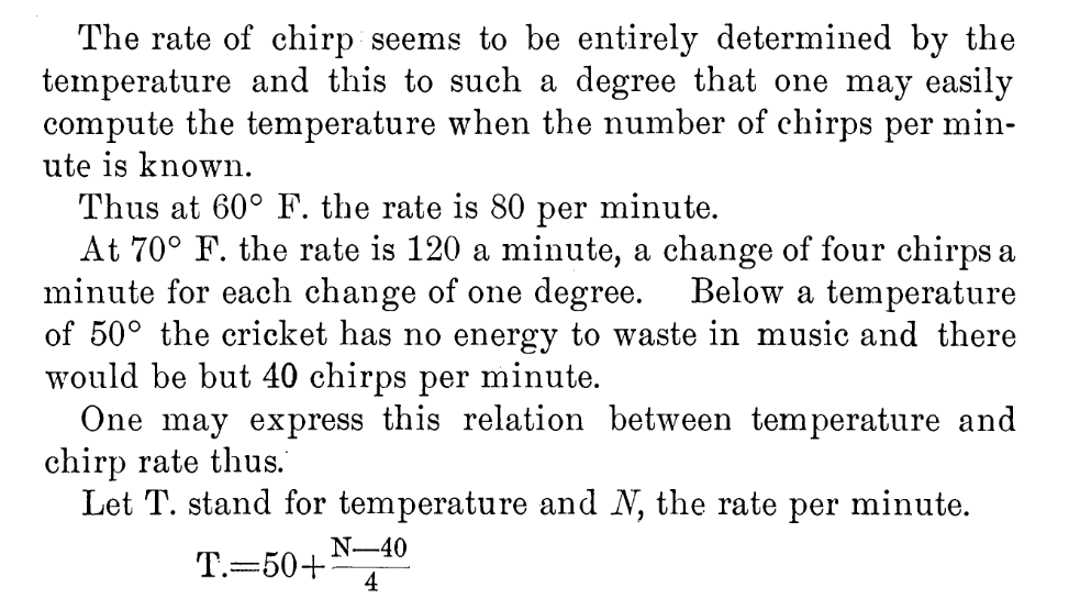
When emulating crickets I’m less interested in the rate of chirps per minute, but rather in the period between chirps. I could also care entirely less about barbarian units, so I reformulated it in °C (t) and milliseconds (p):

t = ⅑ × (40 + 75000 ÷ p)

Since I know that the micro-controller has an internal temperature sensor, I’m particularly interested in the inverse relationship:

p = 15000 ÷ (9 * t ÷ 5 – 8)

I can check this against one of Dolbear’s observations for 70°F (= 21⅑ °C, or 190/9) and 120 chirps / minute (= 2 Hz, or a period of 500 ms):

p = 15000 ÷ (9 * t ÷ 5 – 8)
   = 15000 ÷ (9 * (190 ÷ 9) ÷ 5 – 8)
   = 15000 ÷ (190 ÷ 5 – 8)
   = 15000 ÷ 30
   = 500

Now I’ve got the timing worked out, how about the chirp sound. From a couple of recordings of cricket meadows I’ve made over the years, I observed:

  1. The total duration of a chirp is about ⅛ s
  2. A chirp is made up of four distinct events:
    • a quieter short tone;
    • a longer louder tone of a fractionally higher pitch;
    • the same longer louder tone repeated;
    • the first short tone repeated
  3. There is a very short silence between each tone
  4. Each cricket appears to chirp at roughly the same pitch: some slightly lower, some slightly higher
  5. The pitch of the tones is in the range 4500–5000 Hz: around D8 on the music scale

I didn’t attempt to model the actual stridulating mechanism of a particular species of cricket. I made what sounded sort of right to me. Hey, if Amos Dolbear could make stuff up and get it accepted as a “law”, I can at least get away with pulse width modulation and tiny tinny speakers …

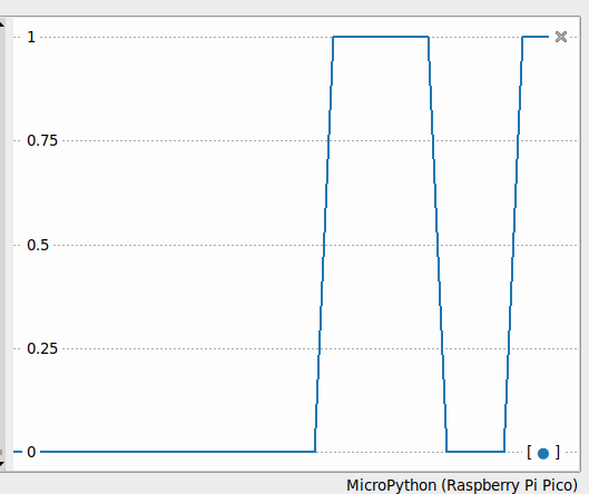
This is the profile I came up with:

  • 21 ms of 4568 Hz at 25% duty cycle
  • 7 ms of silence
  • 28 ms of 4824 Hz at 50% duty cycle
  • 7 ms of silence
  • 28 ms of 4824 Hz at 50% duty cycle
  • 7 ms of silence
  • 21 ms of 4568 Hz at 25% duty cycle
  • 7 ms of silence

That’s a total of 126 ms, or ⅛ish seconds. In the code I made each instance play at a randomly-selected relative pitch of ±200 Hz on the above numbers.

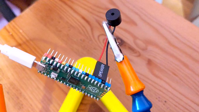
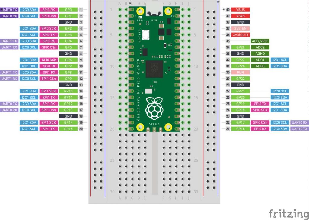
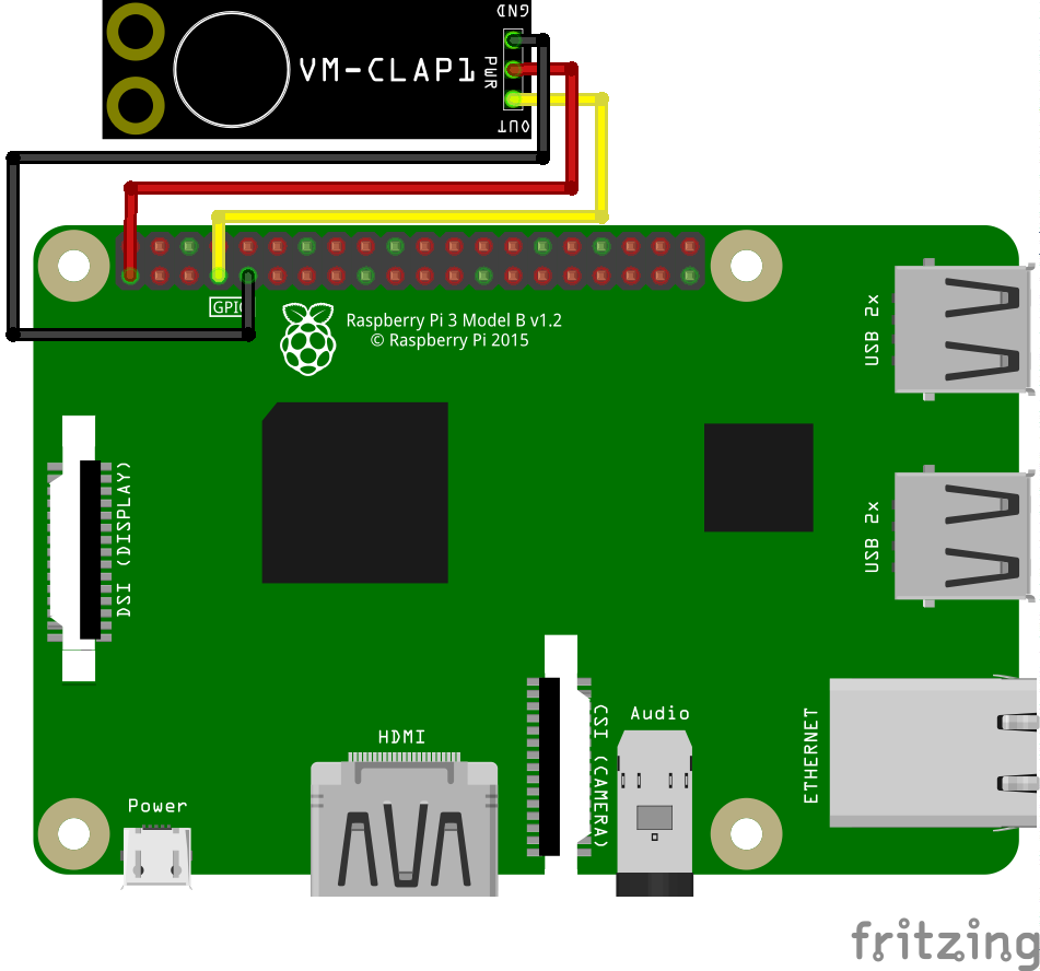
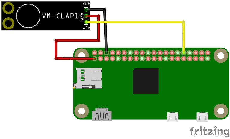
For the speaker, I have a bunch of cheap PC motherboard beepers. They have a Dupont header that spans four pins on a Raspberry Pi Pico header, so if you put one on the ground pin at pin 23, the output will be connected to pin 26, aka GPIO 20:

Raspberry Pi Pico with small piezo speaker connected to pins 23 (ground) and 26 (GPIO 20)
from a post where I did a very, very bad thing: Nyan Cat, except it gets faster — RTTTL on the Raspberry Pi Pico

So — finally — here’s the MicroPython code:

# cricket thermometer simulator - scruss, 2024-02
# uses a buzzer on GPIO 20 to make cricket(ish) noises
# MicroPython - for Raspberry Pi Pico
# -*- coding: utf-8 -*-

from machine import Pin, PWM, ADC, freq
from time import sleep_ms, ticks_ms, ticks_diff
from random import seed, randrange

freq(125000000)  # use default CPU freq
seed()  # start with a truly random seed
pwm_out = PWM(Pin(20), freq=10, duty_u16=0)  # can't do freq=0
led = Pin("LED", Pin.OUT)
sensor_temp = machine.ADC(4)  # adc channel for internal temperature
TOO_COLD = 10.0  # crickets don't chirp below 10 °C (allegedly)
temps = []  # for smoothing out temperature sensor noise
personal_freq_delta = randrange(400) - 199  # different pitch every time
chirp_data = [
    # cadence, duty_u16, freq
    # there is a cadence=1 silence after each of these
    [3, 16384, 4568 + personal_freq_delta],
    [4, 32768, 4824 + personal_freq_delta],
    [4, 32768, 4824 + personal_freq_delta],
    [3, 16384, 4568 + personal_freq_delta],
]
cadence_ms = 7  # length multiplier for playback


def chirp_period_ms(t_c):
    # for a given temperature t_c (in °C), returns the
    # estimated cricket chirp period in milliseconds.
    #
    # Based on
    # Dolbear, Amos (1897). "The cricket as a thermometer".
    #   The American Naturalist. 31 (371): 970–971. doi:10.1086/276739
    #
    # The inverse function is:
    #     t_c = (75000 / chirp_period_ms + 40) / 9
    return int(15000 / (9 * t_c / 5 - 8))


def internal_temperature(temp_adc):
    # see pico-micropython-examples / adc / temperature.py
    return (
        27
        - ((temp_adc.read_u16() * (3.3 / (65535))) - 0.706) / 0.001721
    )


def chirp(pwm_channel):
    for peep in chirp_data:
        pwm_channel.freq(peep[2])
        pwm_channel.duty_u16(peep[1])
        sleep_ms(cadence_ms * peep[0])
        # short silence
        pwm_channel.duty_u16(0)
        pwm_channel.freq(10)
        sleep_ms(cadence_ms)


led.value(0)  # led off at start; blinks if chirping
### Start: pause a random amount (less than 2 s) before starting
sleep_ms(randrange(2000))

while True:
    loop_start_ms = ticks_ms()
    sleep_ms(5)  # tiny delay to stop the main loop from thrashing
    temps.append(internal_temperature(sensor_temp))
    if len(temps) > 5:
        temps = temps[1:]
    avg_temp = sum(temps) / len(temps)
    if avg_temp >= TOO_COLD:
        led.value(1)
        loop_period_ms = chirp_period_ms(avg_temp)
        chirp(pwm_out)
        led.value(0)
        loop_elapsed_ms = ticks_diff(ticks_ms(), loop_start_ms)
        sleep_ms(loop_period_ms - loop_elapsed_ms)

There are a few more details in the code that I haven’t covered here:

  1. The program pauses for a short random time on starting. This is to ensure that if you power up a bunch of these at the same time, they don’t start exactly synchronized
  2. The Raspberry Pi Pico’s temperature sensor can be slightly noisy, so the chirping frequency is based on the average of (up to) the last five readings
  3. There’s no chirping below 10 °C, because Amos Dolbear said so
  4. The built-in LED also flashes if the board is chirping. It doesn’t mimic the speaker’s PWM cadence, though.

Before I show you the next video, I need to say: no real crickets were harmed in the making of this post. I took the bucket outside (roughly -5 °C) and the “crickets” stopped chirping as they cooled down. Don’t worry, they started back up chirping again when I took them inside.

“If You’re Cold They’re Cold, Bring Them Inside”
(video description: a plastic box containing three USB power banks, each with USB cable leading to a Raspberry Pi Pico board. Each board has a small electromagnetic speaker attached between ground and a data pin)

Adding RGB LEDs to an illuminated arcade button

Somewhat painterly view of the button doing its thing. The weird clunking sound is my camera’s continuous focus. For a clearer but more flickery view, see here

Following on from a customer query at Elmwood Electronics, I can confirm that one can install install addressable RGB LEDs/NeoPixels inside one of these large buttons. It’s not the easiest build, so whether one should attempt this is another matter entirely.

You’ll need:

  • Large Arcade Button with LED – 60 mm White (tall version) – this is larger and more domed than the flat-top one that Adafruit sells
  • RGB LEDs – I used a generic 8 LED ring, but anything not too tall and under 45 mm in diameter should fit. Either a 7 X WS2812 5050 RGB LED Ring or Adafruit’s NeoPixel Ring – 12 x WS2812 5050 RGB LED with Integrated Drivers could also work
  • Thin (and I mean thin: I used 28 AWG) Silicone Cover Stranded-Core Wire in several colours. You’ll want to cut this quite long at first, as you have to ease it through some tiny holes in the button assembly. If you solder connectors on the end, you won’t be able to disassemble or install the button without cutting them off. Do I speak from experience here? You betcha!
  • The usual soldering/hot gluing/bending/prying/grabbing/cutting tools you already know and love. In addition, you might consider a non-marring spudger and a pair of small(ish) arterial forceps (aka hemostats, aka Kelly forceps, aka fishing hook removal pliers)

I’m not going to cover soldering the wires to the LED PCB in any depth here. You’ll need three wires: 5 V power, Ground and Data. Even though the LEDs I used need 5 V power, they are quite happy with 3.3 V logic on the data line. They need more than 3.3 V power to light, though.

a large arcade machine style button on the left: it has a clear domed top and a threaded base. On the right is the combined microswitch and LED holder that fits into the button base
The button in two pieces, as you might expect to receive it
the top of the button disassembled into its main parts: bezel ring at top left, threaded lock ring at bottom, and main button mechanism. The mechanism is upside down, so the return spring and button actuators can be seen inside the threaded shaft
Main parts of the button top, once you’ve removed the lock ring
Close up of inside the shaft: return spring and its retainer tabs, and button actuators can be seen
First step is to ease the spring out without bending it too much or breaking the retainer tabs
Close up of inside the shaft: the tips of a pair of forceps have eased the top of the spring past its retainers
I used small forceps to ease the spring out. Once you get it started, it unscrews easily from behind the retainers
Close up of inside the shaft: the button actuators have been pushed down the shaft, allowing the top of the button to be pulled out
Now the spring is out the way, you can squeeze in the actuator tabs and push them down the shaft to liberate the button top
button top components arranged: black threaded button base on left, return spring in the middle, and domed clear top with white underside and white actuators sticking down
The button top disassembled
clear button top attached to its white underside. A blunt metal tool (spudger) is pointed at the push-fit join between the two parts
Carefully lever off the clear top with a blunt tool like a spudger. Now would have been a great time to clean dust and other wee bits off your workspace, as they’ll surely end up inside the button, looking nasty
clear button top separated from its white base. A translucent white diffuser is inside the clear top. The white base has a hollow centre and a circular cavity
The button top opened up. The cavity is about 45 mm in diameter and only a few millimetres deep
The microswitch with the LED holder attached on top. The blade of a blunt metal spudger is inserted under a plastic tab that holds the LED holder onto the switch
Removing the LED holder from the microswitch is done by levering open (gently) the plastic tab that clamps the holder onto the switch.
the LED holder at left, and the bare microswitch. The LED holder has an LED in a white plastic retainer, and below it two spade contacts. The switch has three spade connectors: Com(mon) on the base, and "NO 3" (Normally Open) and "NC 2" on the right side. Normal operation connects COM and NO
LED holder and microswitch separated. For normal button operation, the contacts NO and COM become connected when the button is pressed. The spade contacts on the LED holder look like they should come out, and they will (soon)
LED holder disassembled into two parts. The black LED holder base is on the left, with the two conenctor clips slightly blurry at top. On the right is the LED in its white support, pulled out of the holder base
Pull the LED out from the holder, and you’ll see the metal clips that held it in place. These clips have to come out: I found the pushing them in slightly while pulling down on the spade connector eased them out eventually
White button top underside with an 8 RGB LED ring hot glued into it. Three thin insulated wires (from top: yellow (data), red (5 V) and black (GND)) are previously soldered behind the LED board, and are secured against strain with a large deposit of hot glue
LED ring hot glued into place. Make sure that the wires are properly secured, as you don’t want to take this apart again
threaded button base with clear top fitted, seen from underneath. The white button actuators have been pushed back into place, and the three coloured wires are feeding through the hole in the shaft. The return spring is outside the wires, and is being fitted around the retainers inside the shaft
Fit the clear button top back inside the base, feeding the wires through the shaft. Fitting the return spring back in is a bit more chaotic than getting it out. I ended up jamming it in with forceps, and it seemed to sort out okay despite that
underside of the button shaft, with microswitch attached to LED holder. The wires coming from the LED ring inside the button top have been fed through the small cavities where the original LED holder clips/contacts have been removed. The red/black power wires are on the side towards us, while the yellow data wire is behind the microswitch
The really fiddly bit: feeding the wires through the tiny gaps where the LED holder clips/contacts used to be. Even using thin (28 AWG) silicone covered wire, all three wires couldn’t fit down one side. Make sure the wires are pulled gently through, and aren’t snagged anywhere
Fully reassembled button, with microswitch installed into its bayonet connector in the threaded shaft, and the button actuator lined up with the microswitch lever on the left. The yellow data wire is in front of the microswitch at bottom
Finished! Make sure that the switch actuates properly by lining up the LED holder in the bayonets inside the shaft. Of course, you’ll have wanted to install the button in your project before doing this assembly, as you’ll have to feed those pesky wires back through again if you haven’t …

Autumn in Canada: PicoMite version

more leaves

So I ported autumn in canada from OpenProcessing to PicoMite BASIC on the Raspberry Pi Pico:

a small black screen images with text in the centre: autumn in canada scruss, 2021-11 just watch ...
no leaves
a small black screen images with text in the centre: autumn in canada scruss, 2021-11 just watch ... with one red and one orange maple leaf sitting on top of it
a couple of leaves
a small black screen images with text in the centre: autumn in canada scruss, 2021-11 just watch ... with four red/yellow/orange maple leaves sitting on top of it
more leaves
a small black screen images with text in the centre: autumn in canada scruss, 2021-11 just watch ... with sixteen simulated fallen maple leaves mostly covering it
plenty of leaves
a small black screen image completely covered with many simulated fallen maple leaves
far too many leaves

The biggest thing that tripped me up was that PicoMite BASIC starts arrays at 0. OPTION BASE 1 fixes that oversight. It would have been nice to have OpenProcessing’s HSV colour space, and an editor that could handle lines longer than 80 characters that didn’t threaten to bomb out if you hit the End key, but it’ll serve.

Source below:

' autumn in canada
' scruss, 2021-11
' a take on my https://openprocessing.org/sketch/995420 for picomite

OPTION base 1
RANDOMIZE TIMER
' *** initialize polar coords of leaf polygon and colour array
DIM leaf_rad(24), leaf_ang(24), px%(24), py%(24)
FOR i=1 TO 24
    READ leaf_rad(i)
NEXT i
FOR i=1 TO 24
    READ x
    leaf_ang(i)=RAD(x)
NEXT i

DIM integer c%(8)
FOR i=1 TO 8
    READ r%, g%, b%
    c%(i)=RGB(r%,g%,b%)
NEXT i

' *** set up some limits
min_scale%=INT(MIN(MM.HRES, MM.VRES)/8)
max_scale%=INT(MIN(MM.HRES, MM.VRES)/6)
min_angle=-30
max_angle=30
min_x%=min_scale%
min_y%=min_x%
max_x%=MM.HRES - min_x%
max_y%=MM.VRES - min_y%

CLS
TEXT MM.HRES/2, INT(MM.VRES/3), "autumn in canada", "CM"
TEXT MM.HRES/2, INT(MM.VRES/2), "scruss, 2021-11", "CM"
TEXT MM.HRES/2, INT(2*MM.VRES/3), "just watch ...", "CM"

kt%=0
DO
    cx% = min_x% + INT(RND * (max_x% - min_x%))
    cy% = min_y% + INT(RND * (max_y% - min_y%))
    angle = min_angle + RND * (max_angle - min_angle)
    sc% = min_scale% + INT(RND * (max_scale% - min_scale%))
    col% = 1 + INT(RND * 7)
    leaf cx%, cy%, sc%, angle, c%(7), c%(col%)
    kt% = kt% + 1
LOOP UNTIL kt% >= 1024

END

SUB leaf x%, y%, scale%, angle, outline%, fill%
    FOR i=1 TO 24
        px%(i) = INT(x% + scale% * leaf_rad(i) * COS(RAD(angle)+leaf_ang(i)))
        py%(i) = INT(y% - scale% * leaf_rad(i) * SIN(RAD(angle)+leaf_ang(i)))
    NEXT i
    POLYGON 24, px%(), py%(), outline%, fill%
END SUB

' radii
DATA 0.536, 0.744, 0.608, 0.850, 0.719
DATA 0.836, 0.565, 0.589, 0.211, 0.660, 0.515
DATA 0.801, 0.515, 0.660, 0.211, 0.589, 0.565
DATA 0.836, 0.719, 0.850, 0.608, 0.744, 0.536, 1.000
' angles
DATA 270.000, 307.249, 312.110, 353.267, 356.540
DATA 16.530, 18.774, 33.215, 3.497, 60.659, 72.514
DATA 90.000, 107.486, 119.341, 176.503, 146.785, 161.226
DATA 163.470, 183.460, 186.733, 227.890, 232.751, 270.000, 270.000
' leaf colours
DATA 255,0,0, 255,36,0, 255,72,0, 255,109,0
DATA 255,145,0, 255,182,0, 255,218,0, 255,255,0

You could probably use AUTOSAVE and paste the text into the PicoMite REPL. I used an ILI9341 SPI TFT LCD Touch Panel with my Raspberry Pi Pico along with some rather messy breadboard wiring.

Fun fact: the maple leaf polygon points are derived from the official definition of the flag of Canada.

Modding an Adafruit PIR for 3.3 volts

green circuit board covered in surface mount components. A grey wire has been soldered to the output pin of the SOT-89 package 7133-1 voltage regulator
slightly dodgy soldering of a grey jumper wire to the Vout pin of the PIR’s voltage regulator

Consider the Adafruit PIR (motion) sensor (aka PIR Motion Sensor, if you’re in Canada). Simple, reliable device, but only runs from a 5 V supply. Yes, there are smaller PIRs that run off 3.3 V, but if this is what you have, you need to do some soldering. Annoyingly, the sensor on the board is a 3.3 V part, but the carrier was designed in Olden Tymes when King 5 V ruled.

You can try powering it from 3.3 V, but it’ll go all off on its own randomly as its own power supply won’t be supplying enough voltage. There are a couple of sites on how to modify these PIRs that either describe old kit you can’t get any more, or do it completely wrongly. Just one post on the Adafruit support forum gets it right.

One way of doing this is to provide 3.3 V directly to the output pin of the voltage regulator, and ignore the 5 V power line entirely. The regulator’s a SOT89-3 part that looks a bit like this:

71xx-1 SOT-89 package outline, with three pins at the bottom and one large ground tab (connected to centre pin, but not visible) at the top
wee leggy thing

In the photo above, it’s flipped over. Whichever way it’s oriented, we want to put power directly into the Vout pin. There may be easier points to solder this to than a tiny surface mount pin (almost definitely one of the capacitors) but this has held for me.

How to use it in MicroPython? Like the TTP223 capacitive touch sensors I looked at before, a PIR gives a simple off/on output, so you can use something like this:

from machine import Pin
from time import sleep_ms

pir = Pin(21, Pin.IN)

while True:
    print("[", pir.value(), "]")
    sleep_ms(1000)

value() will return 1 if there’s movement, 0 if not. There are trigger time and sensitivity potentiometers to fiddle with on the board if you need to tweak the output.

line graph showing output signal going from 0 to 1, back down to 0 and ending at one over a period of about 20 seconds
Thonny plotter output showing a couple of movement detections. High output (on my device) stays up for about 4 seconds, so you can be pretty leisurely about polling PIRs

Just remember: don’t connect the 5 V power line if you make this mod. I’m not responsible for any smoke emitted if you do — but I can always sell you a replacement …

CardKB mini keyboard with MicroPython

small computer screen with text
*** APPALLING TYPEWRITER ***
** Type stuff, Esc to end **

then further down: "hello I am smol keeb"
it really is the size of a credit card
(running with a SeeedStudio Wio Terminal)

I got one of these CardKB Mini Keyboards to see if I could use it for small interactives with MicroPython devices. It’s very small, and objectively not great as a mass data entry tool. “Better than a Pocket C.H.I.P. keyboard” is how I’d describe the feel. It’s also pretty reliable.

It’s got an I²C Grove connector, and its brains are an ATMega chip just like an Arduino. It’s strictly an ASCII keyboard: that is, it sends the 8-bit ASCII code of the key combination you pressed. It doesn’t send scan codes like a PC keyboard. The driver source is in the CardKB m5-docs, so if you really felt ambitious you could write a scan code-like firmware for yourself.

The device appears at I²C peripheral address 95, and returns a single byte when polled. That byte’s either 0 if no key was pressed, or the character code of what was pressed. The Esc key returns chr(27), and Enter returns CR. If you poll the keyboard too fast it seems to lose the plot a little, so a tiny delay seems to help

Here’s a small demo for MicroPython that acts as the world’s worst typewriter:

# M5Stack CardKB tiny keyboard - scruss, 2021-06
# MicroPython - Raspberry Pi Pico

from machine import Pin, I2C
from time import sleep_ms

i2c = I2C(1, scl=Pin(7), sda=Pin(6))
cardkb = i2c.scan()[0]  # should return 95
if cardkb != 95:
    print("!!! Check I2C config: " + str(i2c))
    print("!!! CardKB not found. I2C device", cardkb,
          "found instead.")
    exit(1)

ESC = chr(27)
NUL = '\x00'
CR = "\r"
LF = "\n"
c = ''

print("*** APPALLING TYPEWRITER ***")
print("** Type stuff, Esc to end **")

while (c != ESC):
    # returns NUL char if no character read
    c = i2c.readfrom(cardkb, 1).decode()
    if c == CR:
        # convert CR return key to LF
        c = LF
    if c != NUL or c != ESC:
        print(c, end='')
    sleep_ms(5)

And here’s the CircuitPython version. It has annoying tiny differences. It won’t let me use the I²C Grove connector on the Wio Terminal for some reason, but it does work much the same:

# M5Stack CardKB tiny keyboard - scruss, 2021-06
# CircuitPython - SeeedStudio Wio Terminal
# NB: can't use Grove connector under CPY because CPY

import time
import board
import busio

i2c = busio.I2C(board.SCL, board.SDA)

while not i2c.try_lock():
    pass

cardkb = i2c.scan()[0]  # should return 95
if cardkb != 95:
    print("!!! Check I2C config: " + str(i2c))
    print("!!! CardKB not found. I2C device", cardkb,
          "found instead.")
    exit(1)

ESC = chr(27)
NUL = '\x00'
CR = "\r"
LF = "\n"
c = ''
b = bytearray(1)

# can't really clear screen, so this will do
for i in range(12):
    print()
print("*** APPALLING TYPEWRITER ***")
print("** Type stuff, Esc to end **")
for i in range(8):
    print()

while (c != ESC):
    # returns NUL char if no character read
    i2c.readfrom_into(cardkb, b)
    c = b.decode()
    if c == CR:
        # convert CR return key to LF
        c = LF
    if c != NUL or c != ESC:
        print(c, end='')
    time.sleep(0.005)

# be nice, clean up
i2c.unlock()

The cheapest Micro SD card interface in the world

a micro-sd adapter with 7 0.1"-pitch header pins  soldered onto its contacts
micro-SD adapter + pins + solder = working SD interface

It’s only a serial SPI interface, but you can’t beat the price. It should only be used with 3.3 V micro-controllers like the Raspberry Pi Pico, since micro-SD cards don’t like 5 V directly at all.

You might want to pre-tin the pins and apply some extra flux on both surfaces, because these pads are thin and you don’t want to melt them. I used my standard SnAgCu lead-free solder without trouble, though.

label sticker image for 7 pins, from left to right DO, GND, CLK, 3V3, GND, DI, CS
got a label maker? This label’s the same length as an SD card is wide, as shown above.
Made entirely with netpbm

You only need to use one of the Ground connections for the card to work.

Quick labelled Fritzing Raspberry Pi Pico layout

half-size breadboard with Raspberry Pi Pico mounted on top. Labels for each of the pin functions are on the left and right
and now, with labels!

Nothing particularly new or innovative here, but if you’re making simple Raspberry Pi Pico circuits and need to explain them to folks, this little Fritzing template might help. It’s mashed up from:

  1. the pinout diagram (chopped and scaled);
  2. the Raspberry Pi Pico Fritzing part.

Since both of these components are from the Raspberry Pi Foundation’s Getting Started documentation, it’s supplied under the same licence.

fritzing: Generic 4×4 Keypad part

This needs work, but I made this keypad part for Fritzing:

Part file (zipped): Generic_4x4_Keypad.zip

You’ll see these parts described as variations on “4×4 Matrix 16 Keypad Keyboard Module 16 Button” on ebay. They’re very simple: if you press a button (say S7), the row pins (R1-4; R2 for S7) and the column pins (C1-C4; C3 for S7) are connected. So pins R2 and C3 are connected when S7 is pressed. You can use the Arduino Keypad library to talk to these, but do remember they use up 8 I/O pins.

It’s not internally routed in Fritzing, and you likely won’t be able to use it for any kind of schematic work, but who uses Fritzing for anything other than pretty pictures?

Teensy USB Keypad

in which I finally learn about Fritzing’s wire alignment facility …

I’ve had a couple of Teensy boards for a while, but a misunderstanding that they needed a load of of extra software installed (they need one thing, and it’s easy) had kept me away. They’ve got really impressive specs, and they’re especially easy to turn into USB devices like keyboards.

Super-heavy CEECO keypad

Here’s a little demo that turns a phone keypad — in my case, a ridiculously solid CEECO solid metal keypad designed for institutional use — into a simple USB keyboard. Plug it into any machine (including a Raspberry Pi) and it will be identified as a keyboard. No drivers are required.

The code is based on the standard Arduino Keypad library basic demo. That code was meant for a different keypad, so I eventually found a configuration that worked in the Sparkfun 12 button keypad datasheet. Rather than printing characters to the serial port, I used calls to Teensy’s USB Keyboard library instead.

The pinout is (from left to right, key side up):

  1. do not connect
  2. Column 2
  3. Row 1
  4. Column 1
  5. Row 4
  6. Column 3
  7. Row 3
  8. Row 2
  9. n/c

There’s no reason why this wouldn’t work with those very cheap 4×4 button matrix keypads for Arduino too with only minor modifications. Those keypads use 8 data lines, and they’re arranged (I think) as rows 1-4 on pins 1-4 and columns 1-4 are pins 5-8. columns 4-1 then rows 1-4 from the top of the pin connector down:

The Teensy USB keyboard isn’t limited to sending single characters: a single button press could trigger sending a whole string. I haven’t yet thought out any major uses for this (except “Crypto!”, which is my usual idea when I have no idea what I’m doing), but you might have better plans.

Update, 2020-04: These keypads don’t have diodes on every key to prevent key ghosting if you press multiple keys. Despite what the Arduino Playground Keypad section might tell you, you can’t do useful multi-key/rollover detection with them.

VM-CLAP1 👏 sensor + gpiozero on Raspberry Pi

Well, that was easy!

Since the Verbal Machines VM-CLAP1 sensor is an open collector type — that is, it sinks current when triggered — it behaves like a simple button to gpiozero, the Raspberry Pi Python GPIO library. If you attach a callback function to the sensor’s when_pressed event, your Python script will call that function every time it registers a clap.

The wiring is as simple as it could be:

 VM-CLAP1: Raspberry Pi:
 ========= =============
      GND → GND
      PWR → 3V3
      OUT → GPIO 4

This example code just prints clap! when the board picks up a 👏:

#!/usr/bin/env python3
# -*- coding: utf-8 -*-

# Raspberry Pi gpiozero test for
# Verbal Machines VM-CLAP1 clap sensor
#   scruss - 2017-06
#
# Wiring:
#
#  VM-CLAP1:    Raspberry Pi:
#  =========    =============
#    GND     →   GND
#    PWR     →   3V3
#    OUT     →   GPIO 4

from gpiozero import Button
from signal import pause

def clapping():
        print("clap!")

clap = Button(4)
clap.when_pressed = clapping
pause()

This is a trivial example, but at least it shows that anything you can do with a button, you can also do with this hand-clap sensor.

Clap Sensor part for Fritzing

I have no idea if this wiring would work, but it’s pretty …

For work, I blogged about Verbal MachinesHand Clap Sensor VM-CLAP1 (“Clap on 👏👏, Clap off 👏👏 – Elmwood Electronics”). I’ve made a preliminary part for Fritzing for the board: VM-CLAP1 Clap Sensor for Fritzing.zip

It should work in Breadboard and Schematic mode, but absolutely doesn’t work in PCB mode. This shouldn’t be a problem, as it’s only available as a standalone board. Fritzing doesn’t have any way to create new parts from scratch any more, so I had to base it on a somewhat similar-looking board, the SparkFun Electret Microphone Breakout.

I’m looking forward to see what I can do with gpiozero and the clap sensor.

Blinking on and off with the 74LS42

I want to make an edge-lit numeric display. These were a common technology before numeric LEDs were available. They use 10 illuminated slides to display individual numbers. Here’s my first try at the display:

Homebrew edge lit numeralsThe 74LS42 logic chip (4-Line BCD to 10-Line Decimal Decoder) seems a likely candidate to drive such a display. You feed it a 4-bit binary-coded decimal input, and the chip activates one of ten outputs. It’s a low-voltage version of the old 7441 chip used for driving Nixie tubes. Here’s what I got working as a demo of the 7442, driven by an Arduino:

(Video link for the iframe-averse: https://www.youtube.com/watch?v=cETGB2M8iUw)

From the video you can see that:

  1. The 7442 only passes inputs from 0 (0000b) to 9 (1001b). All other inputs result in no output.
  2. The outputs are really more like 1–10 than 0–9, as a zero input activates the first output.

Making a clean breadboard layout for this circuit was a little more work than I’d anticipated. It just fits on a half-sized breadboard:

Simple 7442 demo circuit, showing BCD inputs (green) and decimal outputs (orange)

Because the 7442 will only activate one output at a time, it’s okay to use a single current-limiting resistor for all ten output LEDs. The chip also uses active low outputs: the outputs go from high to low when activated. The negative side of each LED goes to an output pin, and the chip sinks current when an output is selected, lighting the LED.

The components get in the way of seeing the wiring, so here’s another picture from Fritzing with just the wires and the breadboard:

7442-no_componentsApart from the 74LS42 chip itself, the components I used were 10× 3mm orange LEDs on the outputs and 4× 3mm green LEDs on the inputs. I don’t have a spec for them (they were from a bargain selection box from PCBoard.ca) so my use of ridiculously precise 332 Ω 1% resistors to limit current is a little unnecessary. (I have a bunch of these precision resistors from a project that didn’t go ahead, so using them is cheaper for me than digging about for a 5% one.)

Finally, here’s the Arduino sketch I wrote to drive the chip for the demo video. All it does is cycle through digital outputs 4–7, incrementing a bit every half second.

/*
   SeventyfourFortytwo - Arduino demo of a
   74LS42 - 4-line BCD to 10-line decimal decoder
   Steps through 0-15, two steps per second
   Shows the 74LS42's blocking of values 10-15 as invalid

   Wiring:
   Arduino  74LS42
   ======== =======
    4      - 15  Input A (bit 0)
    5      - 14  Input B (bit 1)
    6      - 13  Input C (bit 2)
    7      - 12  Input D (bit 3)

   scruss - 2016-09-23
*/

int n = 0;

void setup() {
  pinMode(4, OUTPUT);
  pinMode(5, OUTPUT);
  pinMode(6, OUTPUT);
  pinMode(7, OUTPUT);
  digitalWrite(4, LOW);
  digitalWrite(5, LOW);
  digitalWrite(6, LOW);
  digitalWrite(7, LOW);
}

void loop() {
  digitalWrite(4, n & 1);
  digitalWrite(5, n & 2);
  digitalWrite(6, n & 4);
  digitalWrite(7, n & 8);
  n++;
  if (n > 15) n = 0;
  delay(500);
}

If you felt really fancy, you could drive the LED inputs through PWM, and come up with just the right of flicker to make this look like a Nixie tube. You should also be able to chain the inputs through some shift registers, too.

[tɒk bɒks] — a tiny hardware speech synthesizer/TTS

[tÉ’k bÉ’ks]: case
[tÉ’k bÉ’ks]: case
[tÉ’k bÉ’ks]: inside
[tÉ’k bÉ’ks]: inside. The observant amongst you will notice that the speech board is 1/10″ further in than it should be for ideal alignment with the USB serial adapter.
Back in the 1980s, the now-defunct Digital Equipment Corporation (“DEC”) sold a hardware speech synthesizer based on Dennis Klatt’s research at MIT.  These DECTalk boxes were compact and robust, and — despite not having the greatest speech quality — gave valuable speech, telephone and reading accessibility to many people. Stephen Hawking’s distinctive voice is from a pre-DEC version of the MIT hardware.

DEC is long gone, and the licensing of DECTalk has wandered off into mostly software. Much to the annoyance of those in earshot, I’ve always enjoyed dabbling in speech synthesis. DECTalk hardware remains expensive, partly because of demand from electronic music producers (its vocoder-like burr is on countless tracks), but also because there are still many people who rely on it for daily life. I couldn’t justify buying a real DECTalk, but I found this: the Parallax Emic 2 Text-to-Speech Module.  For about $80, this stamp-sized board brings a hardware DECTalk implementation to embedded projects.

The Emic 2 is really marketed to microcontroller hobbyists: Make Your Arduino Speak! sorta thing. But I wanted to make a DECTalk-ish hardware box, with serial input, a speaker, and switchable headphone/line jack.  [tɒk bɒks] (a fair approximation of how I pronounce “Talk Box”) is the result.

Hardware

  • Parallax Emic 2 Text-to-Speech Module
  • OSEPP FTDI USB-Serial Breakout — there are many USB-Serial boards that would do this, but two points in this one’s favour are: i) it has header pins for breadboard use, and ii) I had a spare one.
  • Small 8Ω speaker element — the one I used is most likely a headphone element, bought from Active Surplus (RIP). This should be as small as you can get away with (and still hear) as the USB-Serial connection isn’t designed to supply audio power.
  • Header pins and sockets
  • Toggle switch
  • Small project box with perfboard
  • Jumper wires and solder

Connections

Emic 2             Serial
======             ======
 GND                GND
 5V                 Vcc
 SOUT               RXD
 SIN                TXD

Emic 2             Speaker
======             =======
 SP-                -
 SP+  (via switch)  +

Using it

You’ll need some kind of serial terminal connection. In a pinch, you can use the serial monitor that is in the Arduino development environment. Either way, identify your serial port (/dev/ttyUSBN, COMN:, or /dev/tty-usbserialNNNN) and find a way to send 9600 baud, 8N1 characters to it. Hit Return, and you should be greeted by the Emic 2’s : prompt (or a ?, followed by :). Whether you get the prompt or not depends on whether local echo is set or not. Either way, try sending this line:

SAll watched over by machines of loving grace.

You should hear a voice say the title of Richard Brautigan’s lovely poem All Watched Over by Machines of Loving Grace (caution: video link contains nekkid hippies). You should get the : prompt back once the the speech has stopped. And that’s all there is to it: send an S, followed by up to 1023 bytes of (basically ASCII) text, followed by a newline, and it will be spoken. There’s more detail, of course, in the Emic 2 documentation and the Emic 2 Epson/Fonix DECTalk 501 User’s Guide for changing voices, etc. Yes, you can make it sing. No, you probably shouldn’t, though.

Notes

  1. The Emic 2 has no serial flow control, so you have to wait until the module stops speaking (or you send it the stop command) before you can send more. The easiest way is to poll the serial port and see if there’s the : prompt waiting. Until you see the prompt, any text you send it may be lost.
  2. The Emic 2 is an embedded device; Unicode is a bit of a stretch. It’s supposed to accept ISO Latin-1 8-bit characters (handy for Spanish mode), though.
  3. Starting every speech line with S may make this board incompatible with assistive technology software such as the JAWS screen reader. I don’t think that this was the goal for Emic 2’s designers (Grand Idea Studio), however.
  4. The output from the audio jack has a fair bit of noise on it, and you need to set the volume quite low to avoid hiss and hum. Your experience may be different, as I may have accidentally made a ground loop. There is a faintly  audible click at the start and end of the text, too.
  5. The Emic 2 uses DECTalk v5 commands and phonemes. Many DECTalk resources on the web (like these songs) use v4 or older, which are subtly incompatible. I haven’t found a reliable conversion protocol yet.

To end, here’s the Emic 2’s “Dennis” voice reading all of Brautigan’s All Watched Over By Machines of Loving Grace:


(plain link: molg-dennis-140wpm-16khz.mp3)

(even plainer link if you can’t decode MP2 files: molg-dennis-140wpm.mp3)

(recorded and edited for length with Audacity. No hippies — nekkid, or otherwise — were harmed in the making of this recording.)

Too much packaging, Newark

Newark really need to get a handle on their packaging.

I’d ordered a bluetooth adapter for my multimeter. It needs a little doohickey to attach to my meter, which Newark sent out by separate cover. This is how it turned up:

newark boxes

See the little orange thing on top? That’s the part. It’s 70×40×15 mm, and made in Malaysia. It was packed bubble-wrapped in a sturdy little cardboard box (163×73×43 mm, or 12× the volume of the part). That box was then packed in a very solid box (originally shipped from Penang to Gaffney, SC) measuring  200×200×170 mm; that’s 162× the part’s volume. Finally, that box was inside a third box of 330×245×220 mm, or 424× little doohickeys.

Thing is, the little doohickey is a tough injection moulded polymer part. It could probably be dropped in a padded envelope and survive any mail journey.

We’re going to die out for sure.

signals

Built a simple Function Generator with Frequency Counter over the last couple of nights. It’s pretty basic — 0-~500kHz, 0-12V, Sine or Triangular waves — but good enough for my test needs. The frequency counter is basically an Arduino repackaged to feed the attached LCD. The counter isn’t super accurate, but is within 1% of what my multimeter says.

The kit has a fairly high voltage requirement for DC (>= 15V), but this was solved by a quick trip to Active Surplus. $11 bought me a 15V power supply (which delivers around 19V open circuit) and the right kind of barrel jack.

(Talking of neater meters, I didn’t know mine could support the Bluetooth Adaptor reviewed here. Dad’s old Avo couldn’t do that!)

fun trick noisemaker

I just built my first Atari Punk Console, a simple LM556-based noisemaker beloved of the circuit-bending crowd (and pretty much avoided by everyone else). Jimmie P Rodgers sells a nice board (or kit), and I bought a few boards a while back, and only just built one up now.

The board’s a nicely finished little thing:

… and yes, it really only needs three resistors, three capacitors, and the 556, plus the control pots, power, speaker and all-important on/off button. The APC sounds a little like a drunken, flatulent bee banging around in a lager can, so you really want to be able to turn this thing off.

Jimmie designed this to fit in an Altoids tin, but Catherine had discarded a LUSH Massage Bar Tin which looked just about the right size. The tin is made of butter-soft aluminium, so it’s easy to start holes in it with the awl on my Dutch Army knife. It’s bigger than an Altoids tin, so you don’t have to fight to get things in. Lastly, the LUSH tin is nicely curved, and fits in your hands well.

Wit the lid closed, it looks like this:

And the sound? Well …

not your dad’s multimeter

I’d been surviving on a series of sub-$50 multimeters for years. They’d give an approximation of a reading,then fail miserably in a variety of stupid ways. The last one, a rip-off of an Extech, decided to show me how its wires were connected to the probes. “Barely” is a fair description.

So I thought I’d buy a decent meter. One that had heft and gravitas, like the Avo 8 that my dad used to bring home from work. The Avo — seemingly constructed from bakelite, glass and lead — didn’t just take readings, it told you The Truth on its mirrored scale.

So I bought an Agilent. Reliable company, all the right features, beeps politely only when required; a very, very sensible meter. Then I found these in the package:

Dude, what?! Skins on a meter? Meters aren’t toys. Meters are sensible things used by sensible people. We don’t want our work distracted by thoughts of Space!, America!, Sports!, or Some Kind of Bug Thing Eww Squish It Squish It! If you were able to get “skins” for the Avo 8, they would be about Wisden, sheds, and the TSR2.

Despite the sticky nonsense, it’s a good meter. I also managed to catch a Handheld Digital Multimeter Cash Back Offer, so it’s cheaper than competing Flukes and Extechs.