Adding RGB LEDs to an illuminated arcade button

Somewhat painterly view of the button doing its thing. The weird clunking sound is my camera’s continuous focus. For a clearer but more flickery view, see here

Following on from a customer query at Elmwood Electronics, I can confirm that one can install install addressable RGB LEDs/NeoPixels inside one of these large buttons. It’s not the easiest build, so whether one should attempt this is another matter entirely.

You’ll need:

  • Large Arcade Button with LED – 60 mm White (tall version) – this is larger and more domed than the flat-top one that Adafruit sells
  • RGB LEDs – I used a generic 8 LED ring, but anything not too tall and under 45 mm in diameter should fit. Either a 7 X WS2812 5050 RGB LED Ring or Adafruit’s NeoPixel Ring – 12 x WS2812 5050 RGB LED with Integrated Drivers could also work
  • Thin (and I mean thin: I used 28 AWG) Silicone Cover Stranded-Core Wire in several colours. You’ll want to cut this quite long at first, as you have to ease it through some tiny holes in the button assembly. If you solder connectors on the end, you won’t be able to disassemble or install the button without cutting them off. Do I speak from experience here? You betcha!
  • The usual soldering/hot gluing/bending/prying/grabbing/cutting tools you already know and love. In addition, you might consider a non-marring spudger and a pair of small(ish) arterial forceps (aka hemostats, aka Kelly forceps, aka fishing hook removal pliers)

I’m not going to cover soldering the wires to the LED PCB in any depth here. You’ll need three wires: 5 V power, Ground and Data. Even though the LEDs I used need 5 V power, they are quite happy with 3.3 V logic on the data line. They need more than 3.3 V power to light, though.
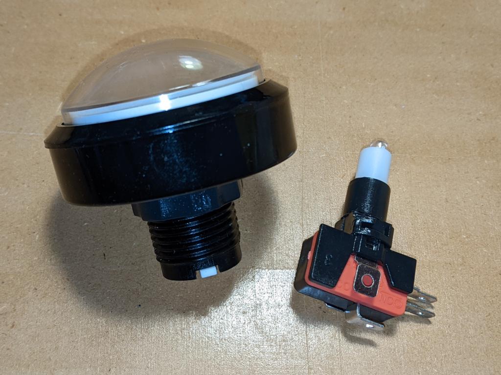
a large arcade machine style button on the left: it has a clear domed top and a threaded base. On the right is the combined microswitch and LED holder that fits into the button base
The button in two pieces, as you might expect to receive it
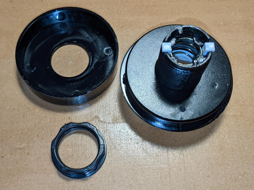
the top of the button disassembled into its main parts: bezel ring at top left, threaded lock ring at bottom, and main button mechanism. The mechanism is upside down, so the return spring and button actuators can be seen inside the threaded shaft
Main parts of the button top, once you’ve removed the lock ring
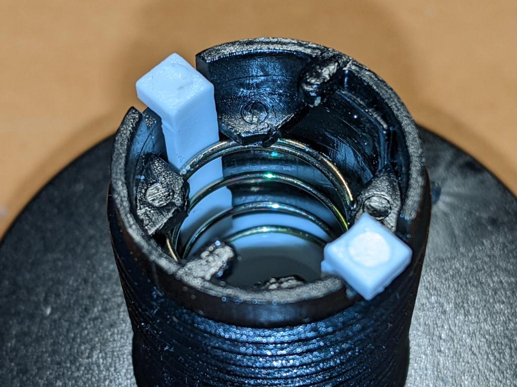
Close up of inside the shaft: return spring and its retainer tabs, and button actuators can be seen
First step is to ease the spring out without bending it too much or breaking the retainer tabs
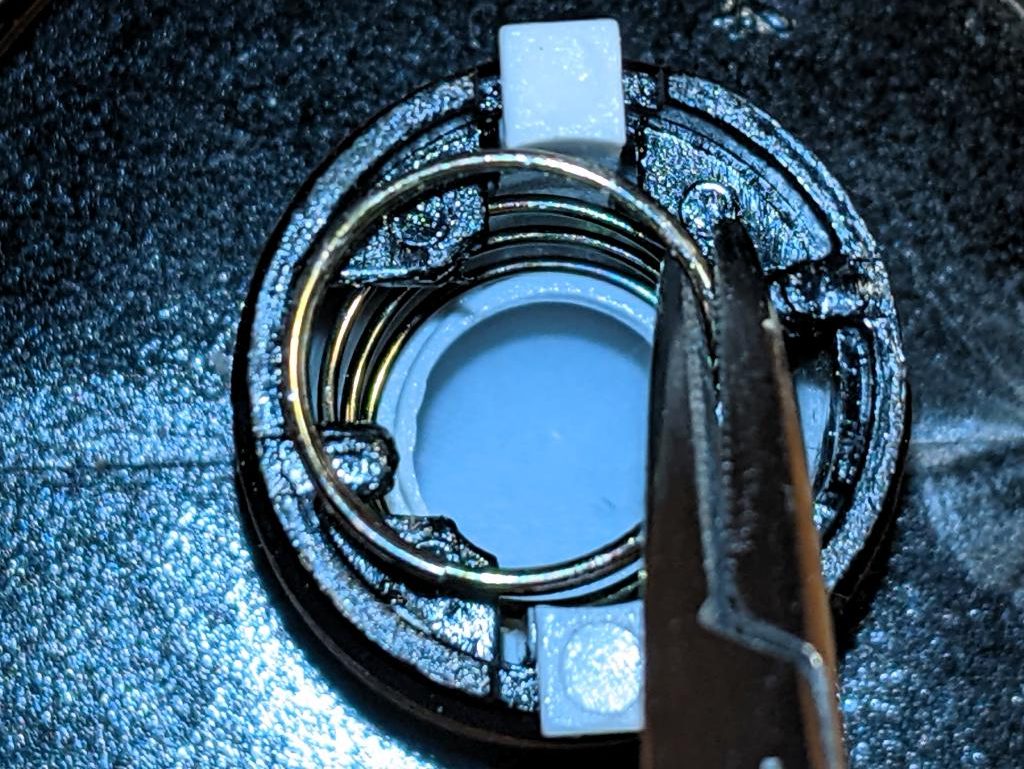
Close up of inside the shaft: the tips of a pair of forceps have eased the top of the spring past its retainers
I used small forceps to ease the spring out. Once you get it started, it unscrews easily from behind the retainers
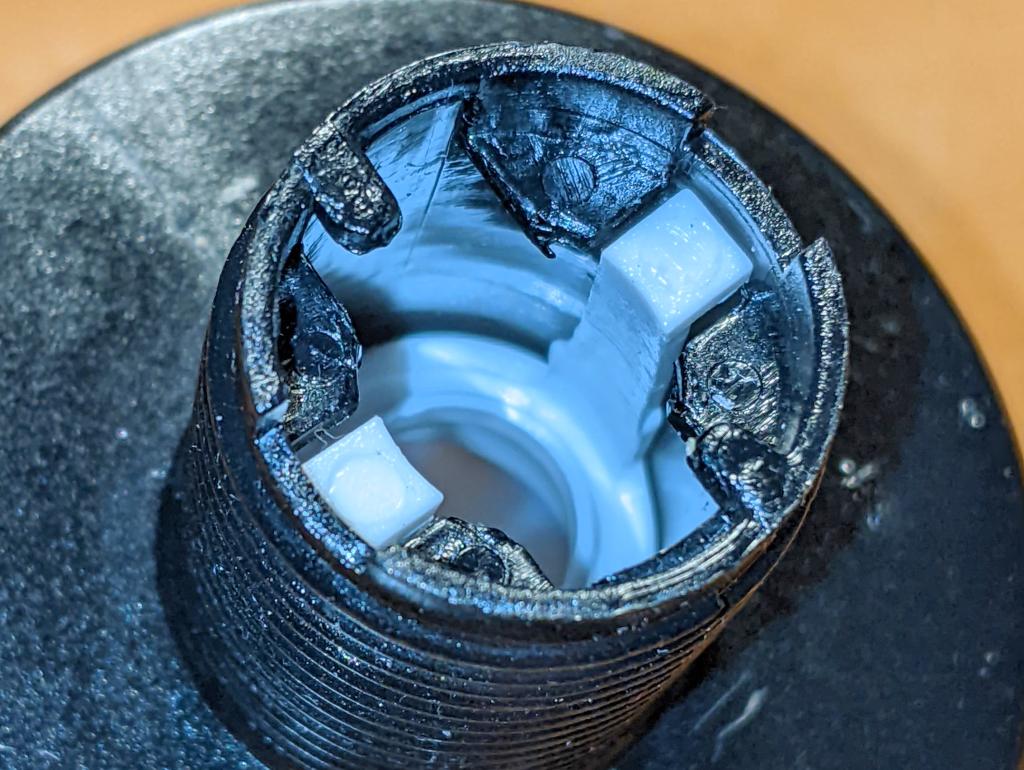
Close up of inside the shaft: the button actuators have been pushed down the shaft, allowing the top of the button to be pulled out
Now the spring is out the way, you can squeeze in the actuator tabs and push them down the shaft to liberate the button top
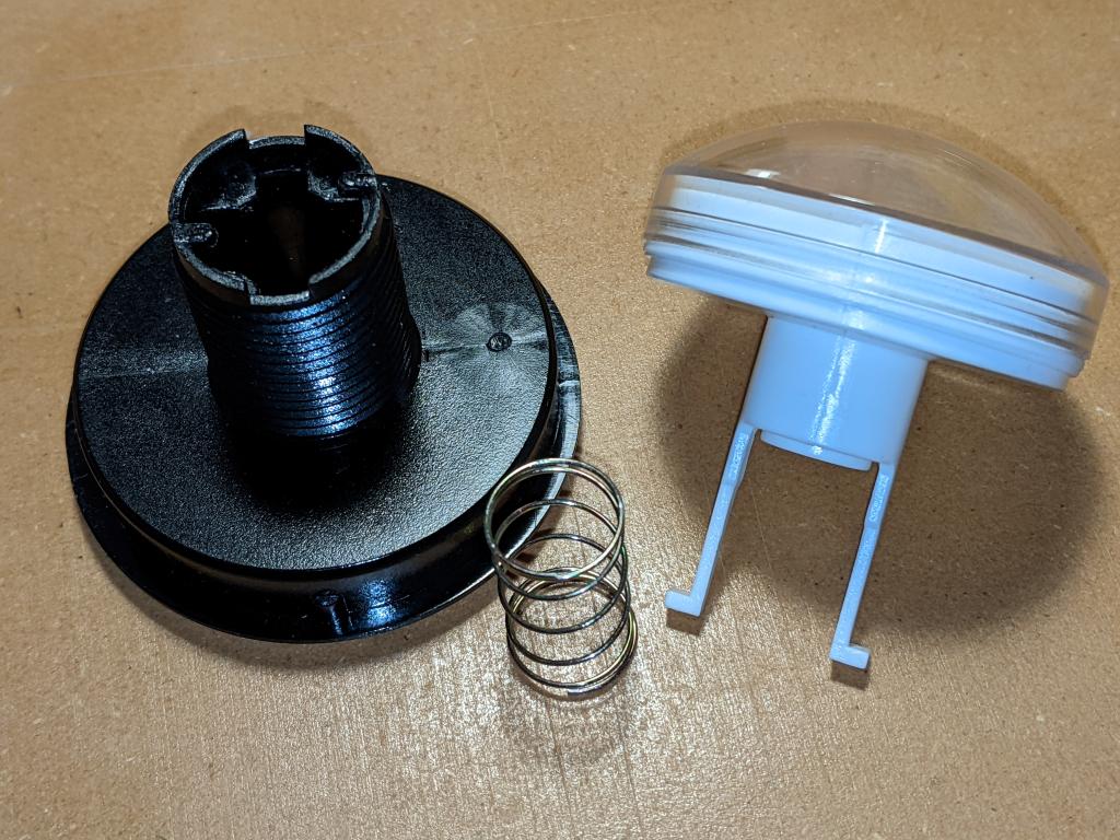
button top components arranged: black threaded button base on left, return spring in the middle, and domed clear top with white underside and white actuators sticking down
The button top disassembled
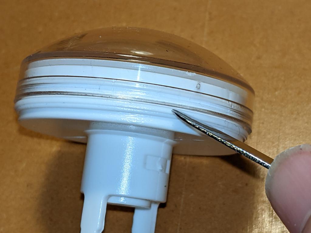
clear button top attached to its white underside. A blunt metal tool (spudger) is pointed at the push-fit join between the two parts
Carefully lever off the clear top with a blunt tool like a spudger. Now would have been a great time to clean dust and other wee bits off your workspace, as they’ll surely end up inside the button, looking nasty
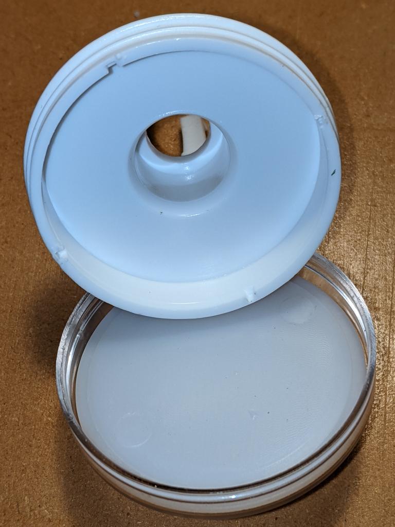
clear button top separated from its white base. A translucent white diffuser is inside the clear top. The white base has a hollow centre and a circular cavity
The button top opened up. The cavity is about 45 mm in diameter and only a few millimetres deep
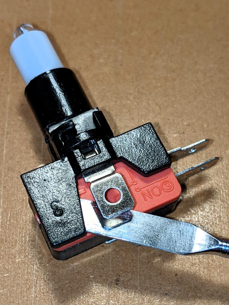
The microswitch with the LED holder attached on top. The blade of a blunt metal spudger is inserted under a plastic tab that holds the LED holder onto the switch
Removing the LED holder from the microswitch is done by levering open (gently) the plastic tab that clamps the holder onto the switch.
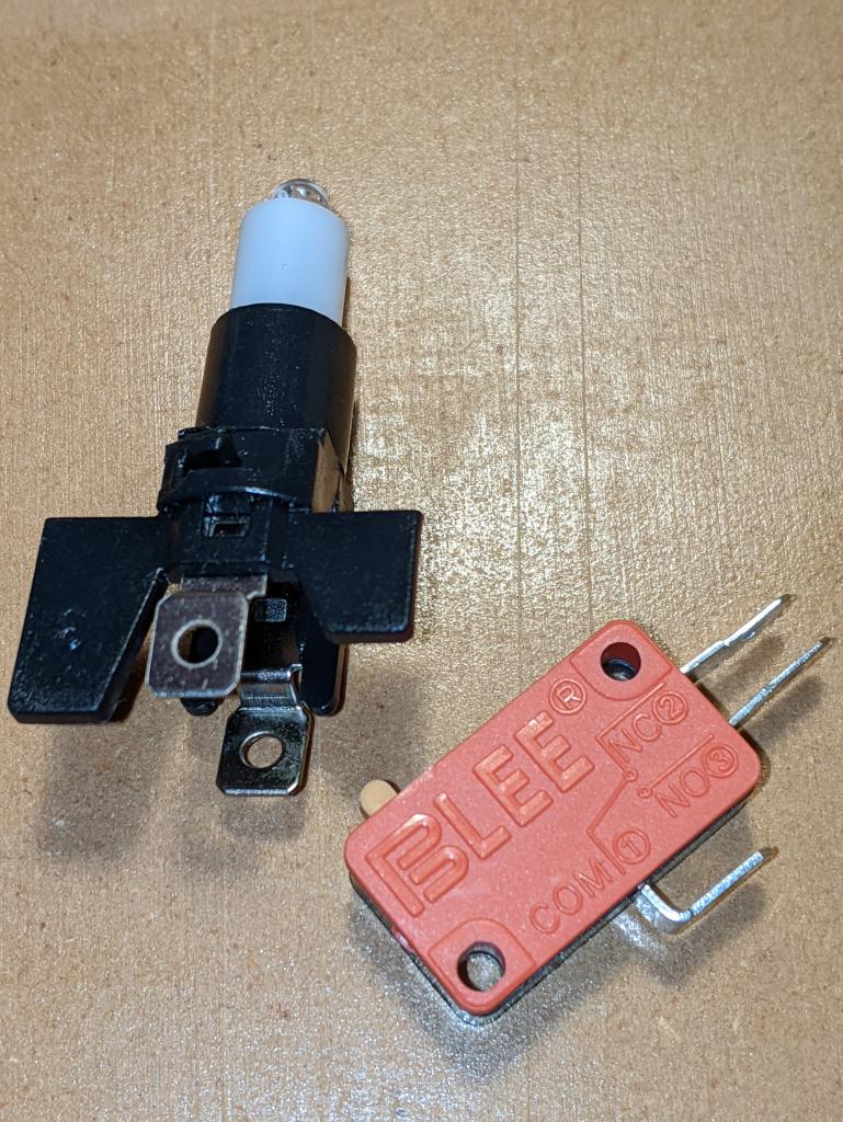
the LED holder at left, and the bare microswitch. The LED holder has an LED in a white plastic retainer, and below it two spade contacts. The switch has three spade connectors: Com(mon) on the base, and "NO 3" (Normally Open) and "NC 2" on the right side. Normal operation connects COM and NO
LED holder and microswitch separated. For normal button operation, the contacts NO and COM become connected when the button is pressed. The spade contacts on the LED holder look like they should come out, and they will (soon)
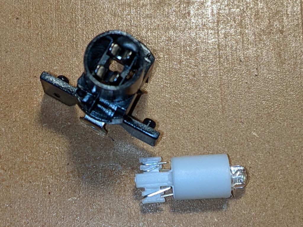
LED holder disassembled into two parts. The black LED holder base is on the left, with the two conenctor clips slightly blurry at top. On the right is the LED in its white support, pulled out of the holder base
Pull the LED out from the holder, and you’ll see the metal clips that held it in place. These clips have to come out: I found the pushing them in slightly while pulling down on the spade connector eased them out eventually
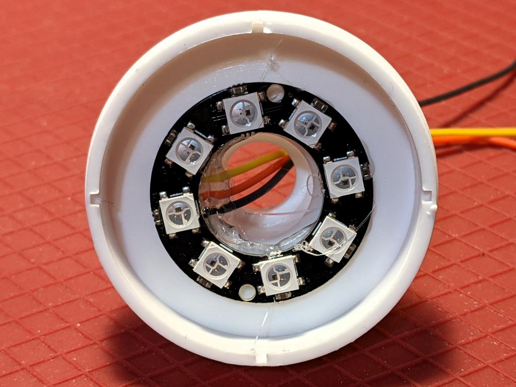
White button top underside with an 8 RGB LED ring hot glued into it. Three thin insulated wires (from top: yellow (data), red (5 V) and black (GND)) are previously soldered behind the LED board, and are secured against strain with a large deposit of hot glue
LED ring hot glued into place. Make sure that the wires are properly secured, as you don’t want to take this apart again
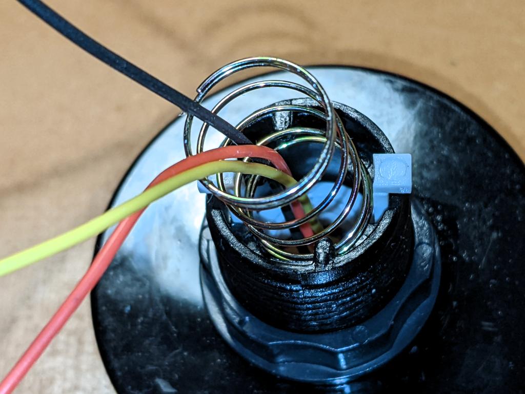
threaded button base with clear top fitted, seen from underneath. The white button actuators have been pushed back into place, and the three coloured wires are feeding through the hole in the shaft. The return spring is outside the wires, and is being fitted around the retainers inside the shaft
Fit the clear button top back inside the base, feeding the wires through the shaft. Fitting the return spring back in is a bit more chaotic than getting it out. I ended up jamming it in with forceps, and it seemed to sort out okay despite that
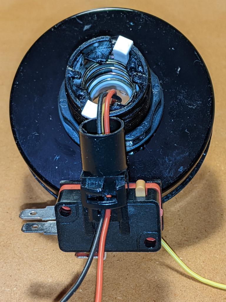
underside of the button shaft, with microswitch attached to LED holder. The wires coming from the LED ring inside the button top have been fed through the small cavities where the original LED holder clips/contacts have been removed. The red/black power wires are on the side towards us, while the yellow data wire is behind the microswitch
The really fiddly bit: feeding the wires through the tiny gaps where the LED holder clips/contacts used to be. Even using thin (28 AWG) silicone covered wire, all three wires couldn’t fit down one side. Make sure the wires are pulled gently through, and aren’t snagged anywhere
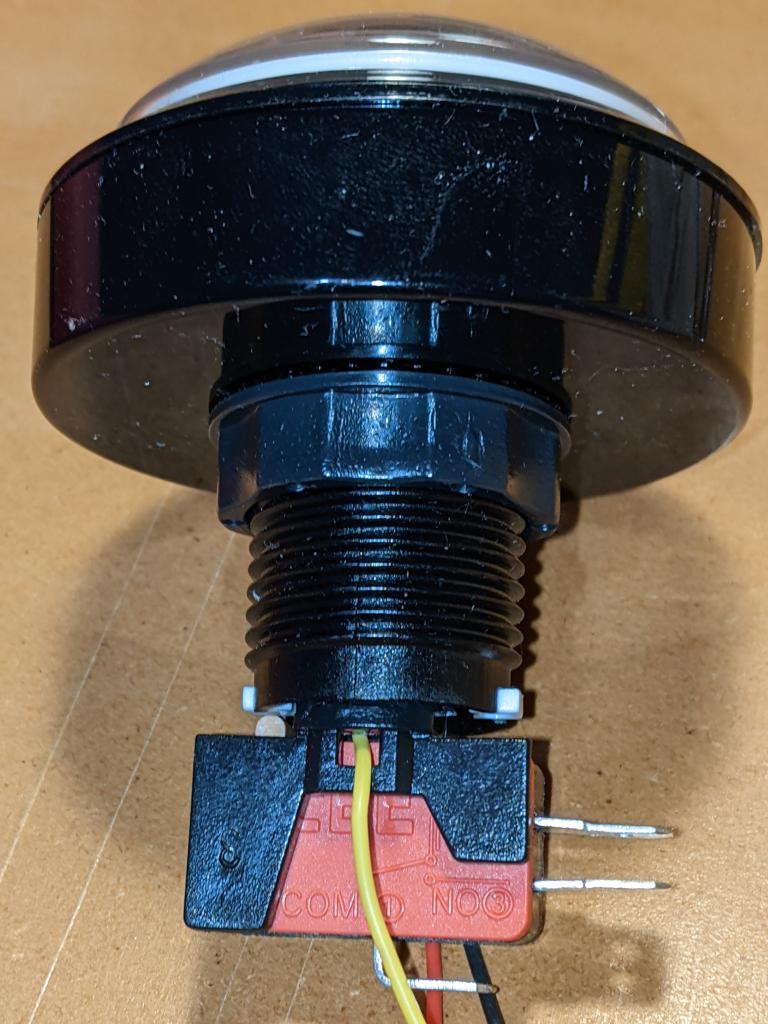
Fully reassembled button, with microswitch installed into its bayonet connector in the threaded shaft, and the button actuator lined up with the microswitch lever on the left. The yellow data wire is in front of the microswitch at bottom
Finished! Make sure that the switch actuates properly by lining up the LED holder in the bayonets inside the shaft. Of course, you’ll have wanted to install the button in your project before doing this assembly, as you’ll have to feed those pesky wires back through again if you haven’t …

Raspberry Pi Pico with TTP223 Touch Sensor

This is almost too trivial to write up, as the TTP223 does exactly what you’d expect it to do with no other components.

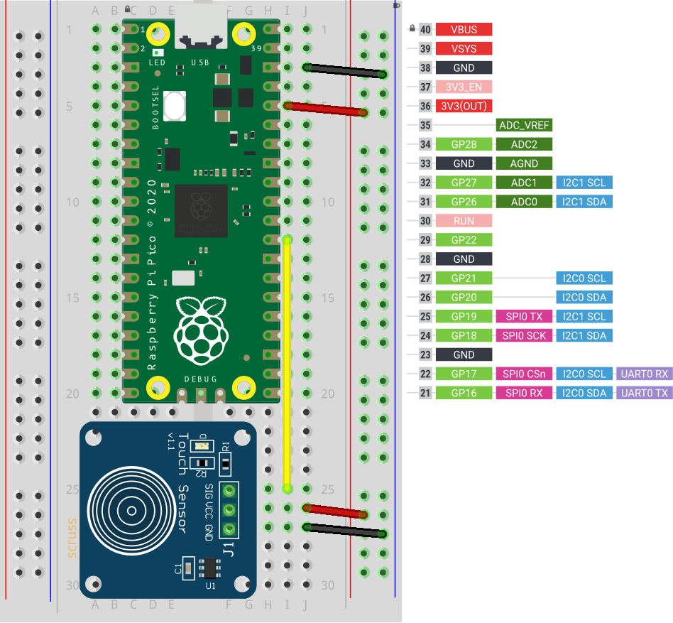
breadboard with Raspberry Pi Pico and small blue capacitive touch sensor
TTP223 sensor board connected to GP22 / physical pin 29

Breakout boards for the TTP223 capacitive touch sensor come in a whole variety of sizes. The ones I got from Simcoe DIY are much smaller, have a different connection order, and don’t have an indicator LED. What they all give you, though, is a single touch/proximity switch for about $1.50

Trivial code to light the Raspberry Pi Pico’s LED when a touch event is detected looks like this:

import machine
touch = machine.Pin(22, machine.Pin.IN)
led = machine.Pin(25, machine.Pin.OUT)

while True:
    led.value(touch.value())

For the default configuration, the sensor’s output goes high while a touch is detected, then goes low. This might not be the ideal configuration for you, so these sensor boards have a couple of solder links you can modify:

  1. Active Low — sometimes you want a switch to indicate a touch with a low / 0 V signal. On the boards I have, the A link controls that: put a blob of solder across it to reverse the switch’s sense.
  2. Toggle — if you want the output to stay latched at one level until you touch it again, a blob of solder across the T link will do that. Unlike a mechanical switch, this won’t stay latched after a power cycle, though.

And that’s all it does. Sometimes it’s nice to have a sensor that does exactly one thing perfectly well.

Raspbian: Getting Alt-Tab to work properly in Openbox/LXDE

I’m still happily using a Raspberry Pi 2B 3 as a lightweight desktop machine. It’s not my main computer, but it’s pleasantly capable. Set up with a couple of paged desktops (or virtual desktops, as we used to call ’em), I can get a bunch of things done with it.

One feature that really irked me, though, was the way that window switching worked. Or, for greater clarity, didn’t work. Openbox, the standard window manager in Raspbian, didn’t allow you to switch to windows on another desktop with Alt+Tab. As I have a smallish screen, I typically have very few windows per desktop, so I want that ability to move from task to task.

This, however, can be fixed. In your ~/.config/openbox/lxde-pi-rc.xml file, change the keybinding sections for Alt+Tab and Alt-Shift+Tab from:

    <!-- Keybindings for window switching -->
    <keybind key="A-Tab">
      <action name="NextWindow"/>
    </keybind>
    <keybind key="A-S-Tab">
      <action name="PreviousWindow"/>
    </keybind>

to

    <!-- Keybindings for window switching -->
    <keybind key="A-Tab">
      <action name="NextWindow">
        <allDesktops>yes</allDesktops>
      </action>
    </keybind>
    <keybind key="A-S-Tab">
      <action name="PreviousWindow">
        <allDesktops>yes</allDesktops>
      </action>
    </keybind>

Log out, log back in, and Alt+Tab across desktops should Just Work. If you’re not using the default pi user, I suspect you’ll have to edit the ~/.config/openbox/lxde-user-rc.xml file instead.

Credit for this tip: user crunchworksyeay on the CrunchBang Linux Forums.

This has been a Memo To Myselfâ„¢ production.

fixing firefox’s fugly fonts on Ubuntu

Update 2015-09: Better yet, install Infinality. It makes font rendering pretty.


Switching back to Linux from Mac is still a process of ironing out minor wrinkles. Take, for example, this abomination (enlarged to show texture):—

Screenshot from 2013-05-19 11:42:18

… No, I’m not talking about Mr Paul’s antics (or the typo in the TP post, either), but the horrid non-matching ligatures (‘attack’, ‘flubbed’, ‘targeting’) in a sea of blocky text. Almost every programme I was running had this problem. Mouse over the image to see how it could look if you apply this easy fix.

Create (or edit) the file ~/.fonts.conf ~/.config/fontconfig/conf.d, and add the following lines:

<match target="font" >
  <edit name="embeddedbitmap" mode="assign">
    <bool>false</bool>
  </edit>
</match>

Log out, log back in again, and text is properly pretty. Yay!