Autumn in Canada: PicoMite version

more leaves

So I ported autumn in canada from OpenProcessing to PicoMite BASIC on the Raspberry Pi Pico:

a small black screen images with text in the centre: autumn in canada scruss, 2021-11 just watch ...
no leaves
a small black screen images with text in the centre: autumn in canada scruss, 2021-11 just watch ... with one red and one orange maple leaf sitting on top of it
a couple of leaves
a small black screen images with text in the centre: autumn in canada scruss, 2021-11 just watch ... with four red/yellow/orange maple leaves sitting on top of it
more leaves
a small black screen images with text in the centre: autumn in canada scruss, 2021-11 just watch ... with sixteen simulated fallen maple leaves mostly covering it
plenty of leaves
a small black screen image completely covered with many simulated fallen maple leaves
far too many leaves

The biggest thing that tripped me up was that PicoMite BASIC starts arrays at 0. OPTION BASE 1 fixes that oversight. It would have been nice to have OpenProcessing’s HSV colour space, and an editor that could handle lines longer than 80 characters that didn’t threaten to bomb out if you hit the End key, but it’ll serve.

Source below:

' autumn in canada
' scruss, 2021-11
' a take on my https://openprocessing.org/sketch/995420 for picomite

OPTION base 1
RANDOMIZE TIMER
' *** initialize polar coords of leaf polygon and colour array
DIM leaf_rad(24), leaf_ang(24), px%(24), py%(24)
FOR i=1 TO 24
    READ leaf_rad(i)
NEXT i
FOR i=1 TO 24
    READ x
    leaf_ang(i)=RAD(x)
NEXT i

DIM integer c%(8)
FOR i=1 TO 8
    READ r%, g%, b%
    c%(i)=RGB(r%,g%,b%)
NEXT i

' *** set up some limits
min_scale%=INT(MIN(MM.HRES, MM.VRES)/8)
max_scale%=INT(MIN(MM.HRES, MM.VRES)/6)
min_angle=-30
max_angle=30
min_x%=min_scale%
min_y%=min_x%
max_x%=MM.HRES - min_x%
max_y%=MM.VRES - min_y%

CLS
TEXT MM.HRES/2, INT(MM.VRES/3), "autumn in canada", "CM"
TEXT MM.HRES/2, INT(MM.VRES/2), "scruss, 2021-11", "CM"
TEXT MM.HRES/2, INT(2*MM.VRES/3), "just watch ...", "CM"

kt%=0
DO
    cx% = min_x% + INT(RND * (max_x% - min_x%))
    cy% = min_y% + INT(RND * (max_y% - min_y%))
    angle = min_angle + RND * (max_angle - min_angle)
    sc% = min_scale% + INT(RND * (max_scale% - min_scale%))
    col% = 1 + INT(RND * 7)
    leaf cx%, cy%, sc%, angle, c%(7), c%(col%)
    kt% = kt% + 1
LOOP UNTIL kt% >= 1024

END

SUB leaf x%, y%, scale%, angle, outline%, fill%
    FOR i=1 TO 24
        px%(i) = INT(x% + scale% * leaf_rad(i) * COS(RAD(angle)+leaf_ang(i)))
        py%(i) = INT(y% - scale% * leaf_rad(i) * SIN(RAD(angle)+leaf_ang(i)))
    NEXT i
    POLYGON 24, px%(), py%(), outline%, fill%
END SUB

' radii
DATA 0.536, 0.744, 0.608, 0.850, 0.719
DATA 0.836, 0.565, 0.589, 0.211, 0.660, 0.515
DATA 0.801, 0.515, 0.660, 0.211, 0.589, 0.565
DATA 0.836, 0.719, 0.850, 0.608, 0.744, 0.536, 1.000
' angles
DATA 270.000, 307.249, 312.110, 353.267, 356.540
DATA 16.530, 18.774, 33.215, 3.497, 60.659, 72.514
DATA 90.000, 107.486, 119.341, 176.503, 146.785, 161.226
DATA 163.470, 183.460, 186.733, 227.890, 232.751, 270.000, 270.000
' leaf colours
DATA 255,0,0, 255,36,0, 255,72,0, 255,109,0
DATA 255,145,0, 255,182,0, 255,218,0, 255,255,0

You could probably use AUTOSAVE and paste the text into the PicoMite REPL. I used an ILI9341 SPI TFT LCD Touch Panel with my Raspberry Pi Pico along with some rather messy breadboard wiring.

Fun fact: the maple leaf polygon points are derived from the official definition of the flag of Canada.
Another Raspberry Pi Pico language: MMBasic

It’s very much a work in progress, but Geoff Graham and Peter Mather’s MMBasic runs nicely on the Raspberry Pi Pico. Development is mostly coordinated on TheBackShed.com forum.

It supports an impressive range of displays and peripherals. The project gives me a very distinct “This is how we do things” vibe, and it’s quite unlike any other Raspberry Pi Pico project.

To show you what MMBasic code looks like, here’s a little demo that uses one of those “Open Smart” LED traffic lights on physical pins 14-16 which cycles through the phases every few seconds:

' traffic light on gp10-12 (green, yellow, red), pins 14-16

' set up ports for output
FOR i=14 TO 16
  SETPIN i, DOUT
  PIN(i)=0
NEXT i

red=16
amber=15
green=14

DO
  ' green on for 5 seconds
  PIN(red)=0
  PIN(green)=1
  PAUSE 5000
  ' amber on for 3 seconds
  PIN(green)=0
  PIN(amber)=1
  PAUSE 3000
  ' red on for 5 seconds
  PIN(amber)=0
  PIN(red)=1
  PAUSE 5000
LOOP

Raspberry Pi Pico with TTP223 Touch Sensor

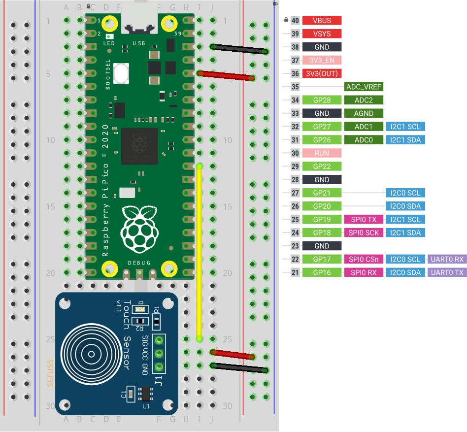
This is almost too trivial to write up, as the TTP223 does exactly what you’d expect it to do with no other components.

breadboard with Raspberry Pi Pico and small blue capacitive touch sensor
TTP223 sensor board connected to GP22 / physical pin 29

Breakout boards for the TTP223 capacitive touch sensor come in a whole variety of sizes. The ones I got from Simcoe DIY are much smaller, have a different connection order, and don’t have an indicator LED. What they all give you, though, is a single touch/proximity switch for about $1.50

Trivial code to light the Raspberry Pi Pico’s LED when a touch event is detected looks like this:

import machine
touch = machine.Pin(22, machine.Pin.IN)
led = machine.Pin(25, machine.Pin.OUT)

while True:
    led.value(touch.value())

For the default configuration, the sensor’s output goes high while a touch is detected, then goes low. This might not be the ideal configuration for you, so these sensor boards have a couple of solder links you can modify:

  1. Active Low — sometimes you want a switch to indicate a touch with a low / 0 V signal. On the boards I have, the A link controls that: put a blob of solder across it to reverse the switch’s sense.
  2. Toggle — if you want the output to stay latched at one level until you touch it again, a blob of solder across the T link will do that. Unlike a mechanical switch, this won’t stay latched after a power cycle, though.

And that’s all it does. Sometimes it’s nice to have a sensor that does exactly one thing perfectly well.

Raspberry Pi Pico: DS18x20 in MicroPython

Updated: Thanks to Ben, who noticed the Fritzing diagrams had the sensors the wrong way round. Fixed now…

Hidden away in the Pico MicroPython guide is a hint that there may be more modules installed in the system than they let on. In the section about picotool, the guide has a seemingly innocuous couple of lines:

frozen modules: _boot, rp2, ds18x20, onewire, uasyncio, uasyncio/core, uasyncio/event, uasyncio/funcs, uasyncio/lock, uasyncio/stream

The third and fourth ‘frozen modules’ are a giveaway: it shows that support for the popular Dallas/Maxim DS18x20 1-Wire temperature sensors is built in. Nowhere else in the guide are they mentioned. I guess someone needs to write them up.

DS18x20 digital temperature sensors – usually sold as DS18B20 by Maxim and the many clone/knock-off suppliers – are handy. They can report temperatures from -55 to 125 °C, although not every sensor will withstand that range. They come in a variety of packages, including immersible sealed units. They give a reliable result, free from ADC noise. They’re fairly cheap, the wiring’s absurdly simple, and you can chain long strings of them together from the same input pin and they’ll all work. What they aren’t, though, is fast: 1-Wire is a slow serial protocol that takes a while to query all of its attached devices and ferry the results back to the controller. But when we’re talking about environmental temperature, querying more often than a few times a minute is unnecessary.

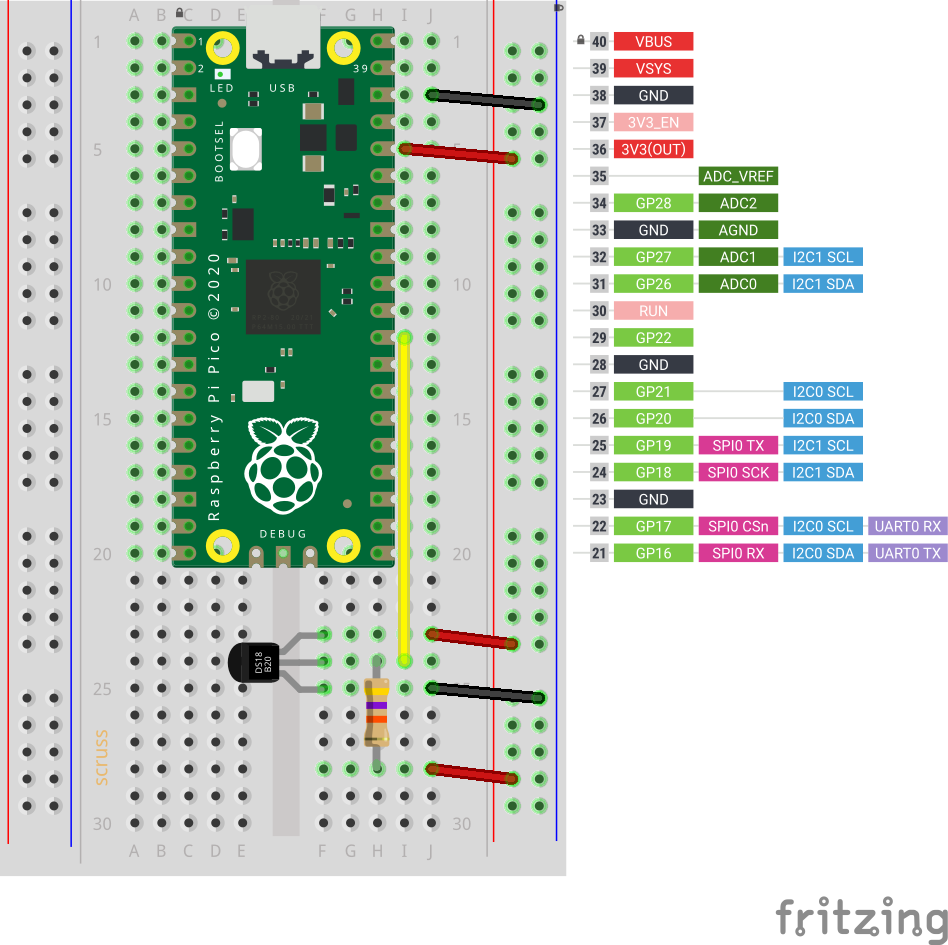
So this is the most complex way you can wire up a DS18x20 sensor:

breadboard with raspberry Pi Pico, DS18x20 sensor with 47 k? pull-up resistor between 3V3 power and sensor data line
Raspberry Pi Pico connected to a single DS18x20 sensor

and this is how it’s wired:

   DS18X20    Pico
   =========  =========
   VDD      ? 3V3
              /
     --47 k?--
    /
   DQ       ? GP22
   GND      ? GND

 (47 k? resistor between DQ and 3V3 as pull-up)

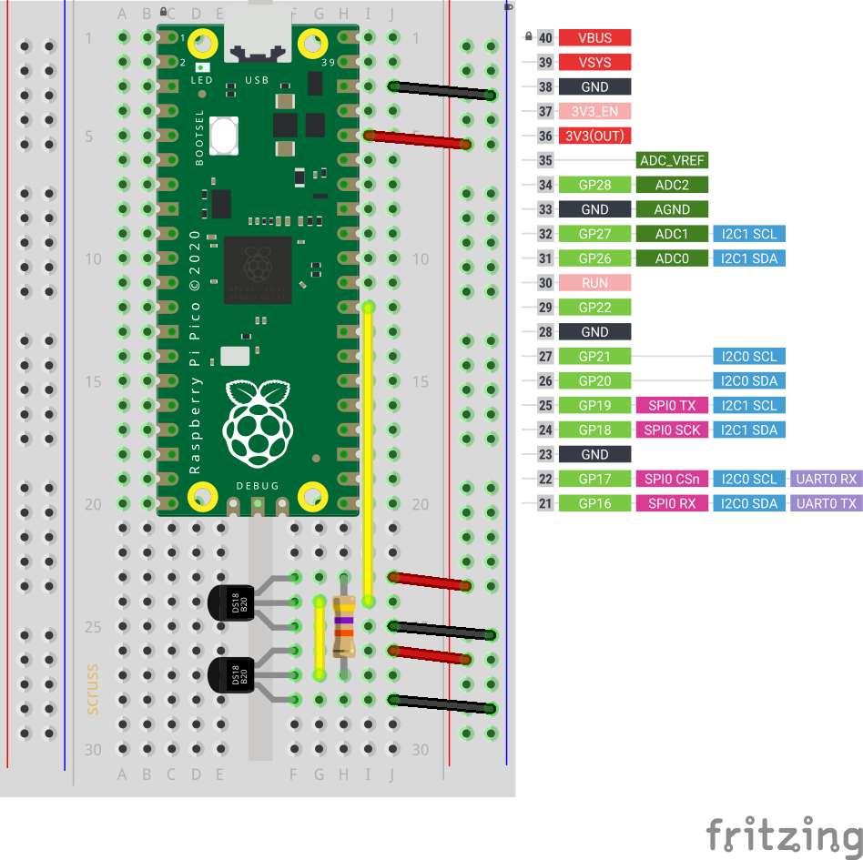
Adding another sensor is no more complicated: connect it exactly as the first, chaining the sensors together –

breadboard with raspberry Pi Pico, two DS18x20 sensors with 47 k? pull-up resistor between 3V3 power and sensor data line
Two DS18x20 sensors, though quite why you’d want two temperature sensors less than 8 mm apart, I’ll never know. Imagine one is a fancy immersible one on a long cable

The code is not complex, either:

# Raspberry Pi Pico - MicroPython DS18X20 Sensor demo
# scruss - 2021-02
# -*- coding: utf-8 -*-

from machine import Pin
from onewire import OneWire
from ds18x20 import DS18X20
from time import sleep_ms
from ubinascii import hexlify    # for sensor ID nice display

ds = DS18X20(OneWire(Pin(22)))
sensors = ds.scan()

while True:
    ds.convert_temp()
    sleep_ms(750)     # mandatory pause to collect results
    for s in sensors:
        print(hexlify(s).decode(), ":", "%6.1f" % (ds.read_temp(s)))
        print()
    sleep_ms(2000)

This generic code will read any number of attached sensors and return their readings along with the sensor ID. The sensor ID is a big ugly hex string (the one I’m using right now has an ID of 284c907997070344, but its friends call it ThreeFourFour) that’s unique across all of the sensors that are out there.

If you’re reading a single sensor, the code can be much simpler:

# Raspberry Pi Pico - MicroPython 1x DS18X20 Sensor demo
# scruss - 2021-02
# -*- coding: utf-8 -*-

from machine import Pin
from onewire import OneWire
from ds18x20 import DS18X20
from time import sleep_ms

ds = DS18X20(OneWire(Pin(22)))
sensor_id = ds.scan()[0]  # the one and only sensor

while True:
    ds.convert_temp()
    sleep_ms(750)         # wait for results
    print(ds.read_temp(sensor_id), " °C")
    sleep_ms(2000)

The important bits of the program:

  1. Tell your Pico you have a DS18x20 on pin GP22:
    ds = DS18X20(OneWire(Pin(22)))
  2. Get the first (and only) sensor ID:
    sensor_id = ds.scan()[0]
  3. Every time you need a reading:
    1. Request a temperature reading:
      ds.convert_temp()
    2. Wait for results to come back:
      sleep_ms(750)
    3. Get the reading back as a floating-point value in °C:
      ds.read_temp(sensor_id)

That’s it. No faffing about with analogue conversion factors and mystery multipliers. No “will it feel like returning a result this time?” like the DHT sensors. While the 1-Wire protocol is immensely complicated (Trevor Woerner has a really clear summary: Device Enumeration on a 1-Wire Bus) it’s not something you need to understand to make them work.

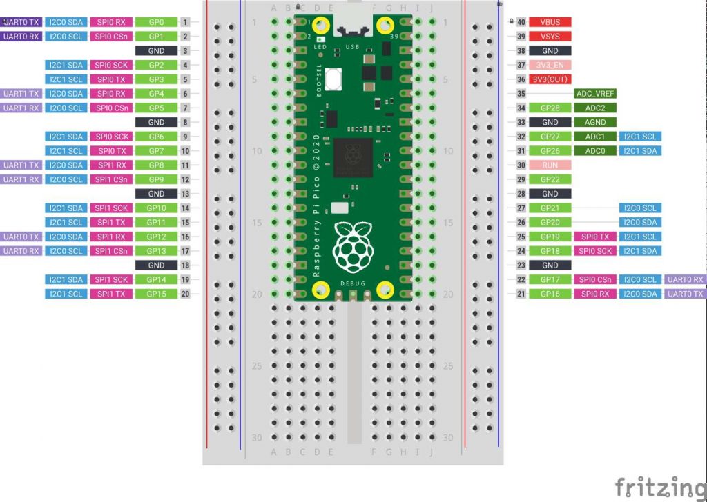
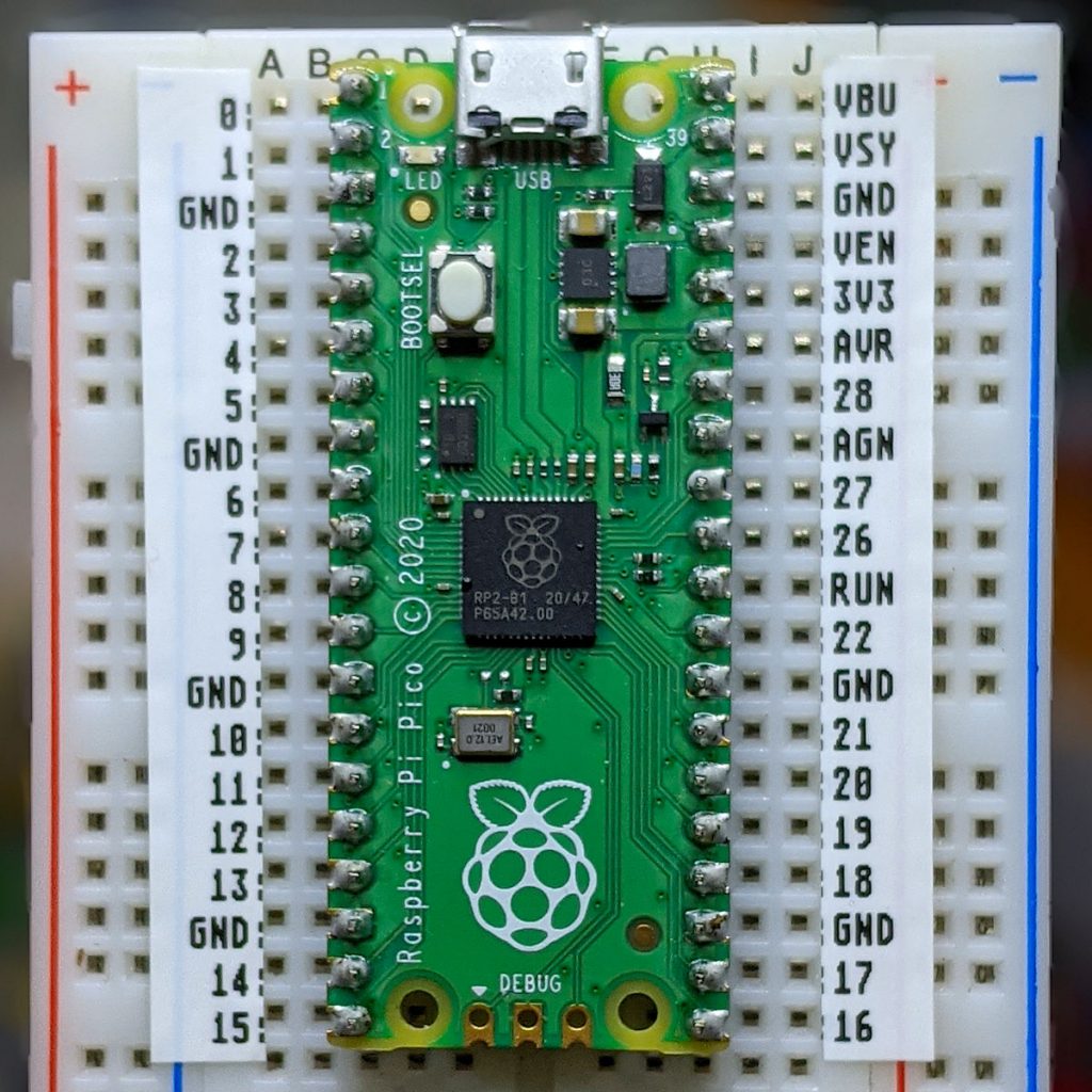
Quick labelled Fritzing Raspberry Pi Pico layout

half-size breadboard with Raspberry Pi Pico mounted on top. Labels for each of the pin functions are on the left and right
and now, with labels!

Nothing particularly new or innovative here, but if you’re making simple Raspberry Pi Pico circuits and need to explain them to folks, this little Fritzing template might help. It’s mashed up from:

  1. the pinout diagram (chopped and scaled);
  2. the Raspberry Pi Pico Fritzing part.

Since both of these components are from the Raspberry Pi Foundation’s Getting Started documentation, it’s supplied under the same licence.

Presentation: Getting Started with MicroPython on the Raspberry Pi Pico

I just gave this talk to the Toronto Raspberry Pi Meetup group: Getting Started with MicroPython on the Raspberry Pi Pico. Slides are here:

or, if you must, pptx:

PDF, for the impatient:

If I were to do this again, I’d drop the messy thermistor code as an example and use a DS18x20, like here: Raspberry Pi Pico: DS18x20 in MicroPython

also, simple potentiometer demo I wrote during the talk: potentiometer.py