Tag: sensors

  • INA219 Current Sensor and MicroPython

    More Micropython programmers — and especially beginners — should know about Awesome MicroPython. It’s a community-curated list of remarkably decent MicroPython libraries, frameworks, software and resources. If you need to interface to a sensor, look there first.

    For example, take the INA219 High Side DC Current Sensor. It’s an I²C sensor able to measure up to 26 V, ±3.2 A. It does this by measuring the voltage across a 0.1 ohm precision shunt resistor with its built-in 12-bit ADC. I got a customer return from the store that was cosmetically damaged but still usable, so I thought I’d try it with the simplest module I could find in Awesome MicroPython and see how well it worked.

    I guess I needed a test circuit too. Using all of what was immediately handy — a resistor I found on the bench and measured at 150.2 ohm — I came up with this barely useful circuit:

    simple circle with 3.3 V DC supply ad two resistors of 150.2 ohms and 0.1 ohms in series
    Should indicate a current of 3.3 / (150.2 + 0.1) = 21.96 mA

    The INA219 would be happier with a much higher current to measure, but I didn’t have anything handy that could do that.

    Looking in Awesome MicroPython’s Current section, I found robert-hh/INA219: INA219 Micropython driver. It doesn’t have much (okay, any) documentation, but it’s a very small module and the code is easy enough to follow. I put the ina219.py module file into the /lib folder of a WeAct Studio RP2040 board, and wrote the following code:

    # INA219 demo - uses https://github.com/robert-hh/INA219
    
    from machine import Pin, I2C
    import ina219
    
    i = I2C(0, scl=Pin(5), sda=Pin(4))
    print("I2C Bus Scan: ", i.scan(), "\n")
    
    sensor = ina219.INA219(i)
    sensor.set_calibration_16V_400mA()
    
    # my test circuit is 3V3 supply through 150.2 ohm resistor
    r_1 = 150.2
    r_s = 0.1  # shunt resistor on INA219 board
    
    # current is returned in milliamps
    print("Current       / mA: %8.3f" % (sensor.current))
    # shunt_voltage is returned in volts
    print("Shunt voltage / mV: %8.3f" % (sensor.shunt_voltage * 1000))
    # estimate supply voltage from known resistance * sensed current
    print("3V3 (sensed)  / mV: %8.3f" % ((r_1 + r_s) * sensor.current))


    with everything wired up like this (Blue = SDA, Yellow = SCL):

    breadboard with RP2040 pico board and INA219 sensor board benath it, and the 150 ohm wired as a circuit on the side
    all of the wires

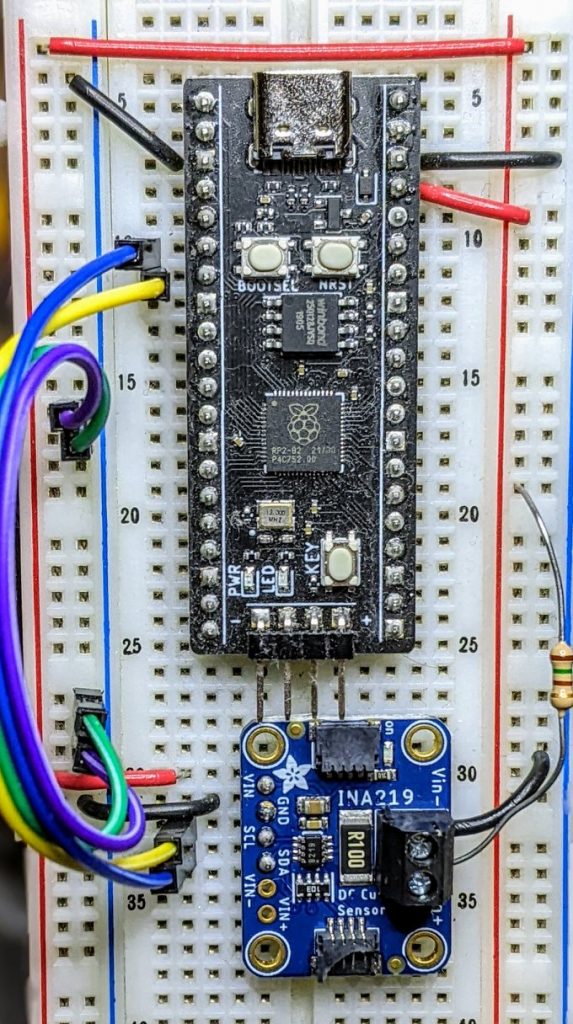
    Running it produced this:

    I2C Bus Scan:  [64] 
    
    Current       / mA:   22.100
    Shunt voltage / mV:    2.210
    3V3 (sensed)  / mV: 3321.630
    

    So it’s showing just over 22 mA: pretty close to what I calculated!

  • Modding an Adafruit PIR for 3.3 volts

    green circuit board covered in surface mount components. A grey wire has been soldered to the output pin of the SOT-89 package 7133-1 voltage regulator
    slightly dodgy soldering of a grey jumper wire to the Vout pin of the PIR’s voltage regulator

    Consider the Adafruit PIR (motion) sensor (aka PIR Motion Sensor, if you’re in Canada). Simple, reliable device, but only runs from a 5 V supply. Yes, there are smaller PIRs that run off 3.3 V, but if this is what you have, you need to do some soldering. Annoyingly, the sensor on the board is a 3.3 V part, but the carrier was designed in Olden Tymes when King 5 V ruled.

    You can try powering it from 3.3 V, but it’ll go all off on its own randomly as its own power supply won’t be supplying enough voltage. There are a couple of sites on how to modify these PIRs that either describe old kit you can’t get any more, or do it completely wrongly. Just one post on the Adafruit support forum gets it right.

    One way of doing this is to provide 3.3 V directly to the output pin of the voltage regulator, and ignore the 5 V power line entirely. The regulator’s a SOT89-3 part that looks a bit like this:

    71xx-1 SOT-89 package outline, with three pins at the bottom and one large ground tab (connected to centre pin, but not visible) at the top
    wee leggy thing

    In the photo above, it’s flipped over. Whichever way it’s oriented, we want to put power directly into the Vout pin. There may be easier points to solder this to than a tiny surface mount pin (almost definitely one of the capacitors) but this has held for me.

    How to use it in MicroPython? Like the TTP223 capacitive touch sensors I looked at before, a PIR gives a simple off/on output, so you can use something like this:

    from machine import Pin
    from time import sleep_ms
    
    pir = Pin(21, Pin.IN)
    
    while True:
        print("[", pir.value(), "]")
        sleep_ms(1000)
    

    value() will return 1 if there’s movement, 0 if not. There are trigger time and sensitivity potentiometers to fiddle with on the board if you need to tweak the output.

    line graph showing output signal going from 0 to 1, back down to 0 and ending at one over a period of about 20 seconds
    Thonny plotter output showing a couple of movement detections. High output (on my device) stays up for about 4 seconds, so you can be pretty leisurely about polling PIRs

    Just remember: don’t connect the 5 V power line if you make this mod. I’m not responsible for any smoke emitted if you do — but I can always sell you a replacement …

  • MQTT Talk tonight

    I’m talking at the Raspberry Pi Toronto Meetup tonight, and if all goes well, the Net-Connected Cowbell will make an appearance:

    My slides: MQTT.odp

    Links: