Hey! This code situation may be changing soon, but this article was written about MicroPython v1.25.0 on RP2040. The situation on the Raspberry Pi Pico W / 2W /RP2350 might be quite different.
Many micro-controllers have timed energy-saving modes you can engage when they are idle. These are typically one of:
light sleep: where memory contents are retained, but some parts of the CPU and peripherals are turned off to reduce current;
deep sleep: memory is cleared, most of the CPU and peripherals are powered off. The CPU will reset fully on restart, so your program has to reload.
While MicroPython on the RP2040 has both machine.lightsleep() and machine.deepsleep() functions, there’s not much difference between them. In fact, the deepsleep() routine is merely lightsleep() followed by reset(). So there isn’t any efficiency gain in using deepsleep over lightsleep.
The functions take one argument: the sleep time, given in milliseconds. The largest value that is accepted is 4294966, or (2**32 // 10**3) - 1. That’s 71′ 34″. If you give a larger number, this exception is thrown: ValueError: sleep too long, and the function returns immediately.
If you’ve used machine.deepsleep(), you might want to know whether your micro-controller was started by applying power, or started from the reset() after deepsleep(). The machine.reset_cause() function returns one of two values:
machine.PWRON_RESET: if the CPU was started from power on, or by briefly grounding the RUN pin;
machine.WDT_RESET: if the CPU was soft reset, either by a watchdog timer or other software reset. This is the state returned after deepsleep().
Other MicroPython ports have more nuanced ways of handling sleep and reset states with better power saving.
If you’re running a tight polling loop and still wish to save a little power, machine.idle() is the recommended method.
If you have a Wemos/LOLIN S3 MINI PRO board, you might find that firmware images don’t flash so well. That’s because the ESP32-S3FH4R2 has 4 MB of flash storage, and most ESP32-S3 boards have 8 MB.
This trims down a standard MicroPython ESP32-S3 firmware from a 4 MB filesystem partition down to 2 MB, and sets the overall flash size to 4 MB. Upload that to your board, and all will be well.
Alternatively, v1.26 supports “4MiB and larger” flash chips. I have confirmed that ESP32_GENERIC_S3-20250724-v1.26.0-preview.bin works as expected:
$ mpremote a1 run boardstats.py
Board       : Generic ESP32S3 module with ESP32S3
Frequency   : 160 MHz
Free Memory : 2061232
File storage: 2036 / 2048 K
In late 2024, SparkFun Electronics relaunched their website. In doing so, they deleted roughly 20 years of archived product information, along with all associated datasheets, schematics and tutorials. Luckily, the Internet Archive’s Wayback Machine has good records of the site, and I was able to recover links to 5934 deleted products.
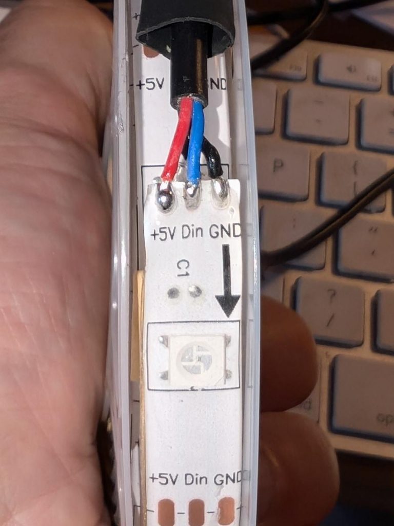
also known as “Monster BASICS Sound reactive RGB+IC Color Flow LED strip”. It’s $5 or so at Dollarama, and includes a USB cable for power and a remote control. It’s two metres long and includes 60 RGB LEDs. Are these really super-cheap NeoPixel clones?
I’m going to keep the USB power so I can power it from a power bank, but otherwise convert it to a string of smart LEDs. We lose the remote control capability.
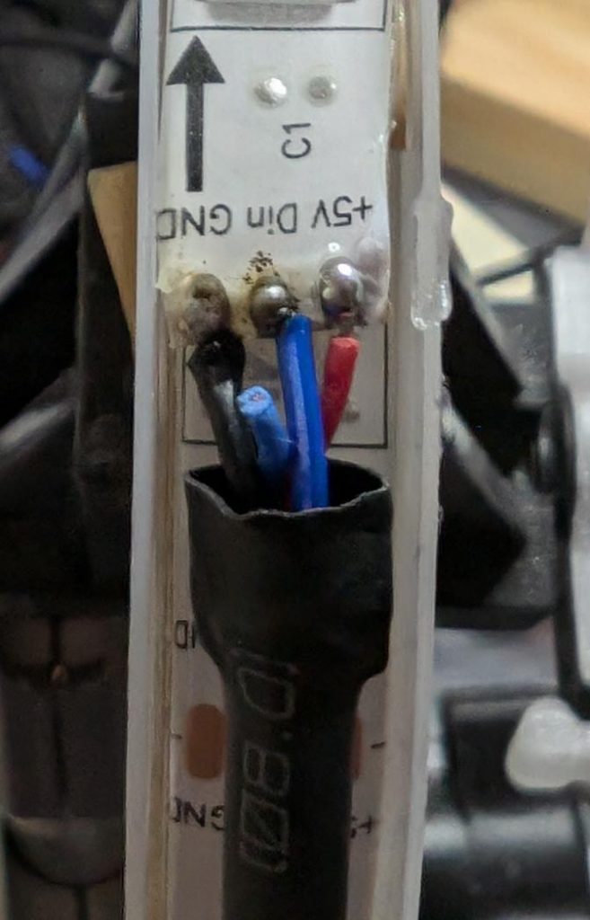
Pull back the heatshrink at the USB end:
… and there are our connectors. We want to disconnect the blue Din (Data In) line from the built in controller, and solder new wires to Din and GND to run from a microcontroller board.
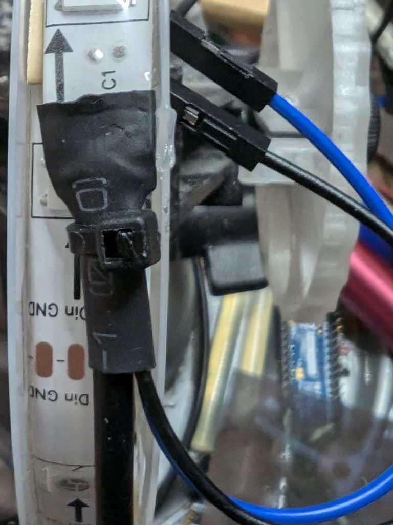
Maybe not the best solder job, but there are new wires feeding through the heatshrink and soldered onto the strip.
Here’s the heatshrink pushed back, and everything secured with a cable tie.
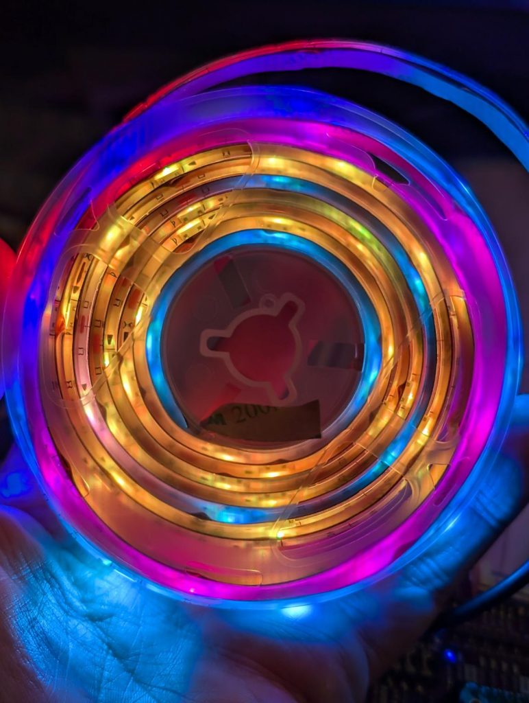
Now to feed it from standard MicroPython NeoPixel code, suitably jazzed up for 60 pixels.
It’s mid-February in Toronto: -10 °C and snowy. The memory of chirping summer fields is dim. But in my heart there is always a cricket-loud meadow.
Short of moving somewhere warmer, I’m going to have to make my own midwinter crickets. I have micro-controllers and tiny speakers: how hard can this be?
more fun than a bucket of simulated crickets (video description: a plastic box containing three USB power banks, each with USB cable leading to a Raspberry Pi Pico board. Each board has a small electromagnetic speaker attached between ground and a data pin)
I could have merely made these beep away at a fixed rate, but I know that real crickets tend to chirp faster as the day grows warmer. This relationship is frequently referred to as Dolbear’s law. The American inventor Amos Dolbear published his observation (without data or species identification) in The American Naturalist in 1897: The Cricket as a Thermometer —
pretty bold assertions there without data eh, Amos old son …?
When emulating crickets I’m less interested in the rate of chirps per minute, but rather in the period between chirps. I could also care entirely less about barbarian units, so I reformulated it in °C (t) and milliseconds (p):
t = ⅑ × (40 + 75000 ÷ p)
Since I know that the micro-controller has an internal temperature sensor, I’m particularly interested in the inverse relationship:
p = 15000 ÷ (9 * t ÷ 5 – 8)
I can check this against one of Dolbear’s observations for 70°F (= 21⅑ °C, or 190/9) and 120 chirps / minute (= 2 Hz, or a period of 500 ms):
Now I’ve got the timing worked out, how about the chirp sound. From a couple of recordings of cricket meadows I’ve made over the years, I observed:
The total duration of a chirp is about ⅛ s
A chirp is made up of four distinct events:
a quieter short tone;
a longer louder tone of a fractionally higher pitch;
the same longer louder tone repeated;
the first short tone repeated
There is a very short silence between each tone
Each cricket appears to chirp at roughly the same pitch: some slightly lower, some slightly higher
The pitch of the tones is in the range 4500–5000 Hz: around D8 on the music scale
I didn’t attempt to model the actual stridulating mechanism of a particular species of cricket. I made what sounded sort of right to me. Hey, if Amos Dolbear could make stuff up and get it accepted as a “law”, I can at least get away with pulse width modulation and tiny tinny speakers …
This is the profile I came up with:
21 ms of 4568 Hz at 25% duty cycle
7 ms of silence
28 ms of 4824 Hz at 50% duty cycle
7 ms of silence
28 ms of 4824 Hz at 50% duty cycle
7 ms of silence
21 ms of 4568 Hz at 25% duty cycle
7 ms of silence
That’s a total of 126 ms, or ⅛ish seconds. In the code I made each instance play at a randomly-selected relative pitch of ±200 Hz on the above numbers.
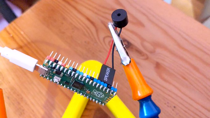
For the speaker, I have a bunch of cheap PC motherboard beepers. They have a Dupont header that spans four pins on a Raspberry Pi Pico header, so if you put one on the ground pin at pin 23, the output will be connected to pin 26, aka GPIO 20:
# cricket thermometer simulator - scruss, 2024-02
# uses a buzzer on GPIO 20 to make cricket(ish) noises
# MicroPython - for Raspberry Pi Pico
# -*- coding: utf-8 -*-

from machine import Pin, PWM, ADC, freq
from time import sleep_ms, ticks_ms, ticks_diff
from random import seed, randrange

freq(125000000)  # use default CPU freq
seed()  # start with a truly random seed
pwm_out = PWM(Pin(20), freq=10, duty_u16=0)  # can't do freq=0
led = Pin("LED", Pin.OUT)
sensor_temp = machine.ADC(4)  # adc channel for internal temperature
TOO_COLD = 10.0  # crickets don't chirp below 10 °C (allegedly)
temps = []  # for smoothing out temperature sensor noise
personal_freq_delta = randrange(400) - 199  # different pitch every time
chirp_data = [
    # cadence, duty_u16, freq
    # there is a cadence=1 silence after each of these
    [3, 16384, 4568 + personal_freq_delta],
    [4, 32768, 4824 + personal_freq_delta],
    [4, 32768, 4824 + personal_freq_delta],
    [3, 16384, 4568 + personal_freq_delta],
]
cadence_ms = 7  # length multiplier for playback


def chirp_period_ms(t_c):
    # for a given temperature t_c (in °C), returns the
    # estimated cricket chirp period in milliseconds.
    #
    # Based on
    # Dolbear, Amos (1897). "The cricket as a thermometer".
    #   The American Naturalist. 31 (371): 970–971. doi:10.1086/276739
    #
    # The inverse function is:
    #     t_c = (75000 / chirp_period_ms + 40) / 9
    return int(15000 / (9 * t_c / 5 - 8))


def internal_temperature(temp_adc):
    # see pico-micropython-examples / adc / temperature.py
    return (
        27
        - ((temp_adc.read_u16() * (3.3 / (65535))) - 0.706) / 0.001721
    )


def chirp(pwm_channel):
    for peep in chirp_data:
        pwm_channel.freq(peep[2])
        pwm_channel.duty_u16(peep[1])
        sleep_ms(cadence_ms * peep[0])
        # short silence
        pwm_channel.duty_u16(0)
        pwm_channel.freq(10)
        sleep_ms(cadence_ms)


led.value(0)  # led off at start; blinks if chirping
### Start: pause a random amount (less than 2 s) before starting
sleep_ms(randrange(2000))

while True:
    loop_start_ms = ticks_ms()
    sleep_ms(5)  # tiny delay to stop the main loop from thrashing
    temps.append(internal_temperature(sensor_temp))
    if len(temps) > 5:
        temps = temps[1:]
    avg_temp = sum(temps) / len(temps)
    if avg_temp >= TOO_COLD:
        led.value(1)
        loop_period_ms = chirp_period_ms(avg_temp)
        chirp(pwm_out)
        led.value(0)
        loop_elapsed_ms = ticks_diff(ticks_ms(), loop_start_ms)
        sleep_ms(loop_period_ms - loop_elapsed_ms)
There are a few more details in the code that I haven’t covered here:
The program pauses for a short random time on starting. This is to ensure that if you power up a bunch of these at the same time, they don’t start exactly synchronized
The Raspberry Pi Pico’s temperature sensor can be slightly noisy, so the chirping frequency is based on the average of (up to) the last five readings
There’s no chirping below 10 °C, because Amos Dolbear said so
The built-in LED also flashes if the board is chirping. It doesn’t mimic the speaker’s PWM cadence, though.
Before I show you the next video, I need to say: no real crickets were harmed in the making of this post. I took the bucket outside (roughly -5 °C) and the “crickets” stopped chirping as they cooled down. Don’t worry, they started back up chirping again when I took them inside.
“If You’re Cold They’re Cold, Bring Them Inside” (video description: a plastic box containing three USB power banks, each with USB cable leading to a Raspberry Pi Pico board. Each board has a small electromagnetic speaker attached between ground and a data pin)
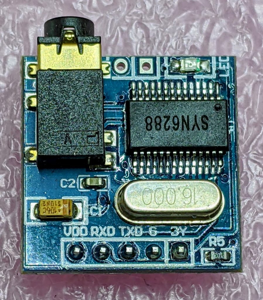
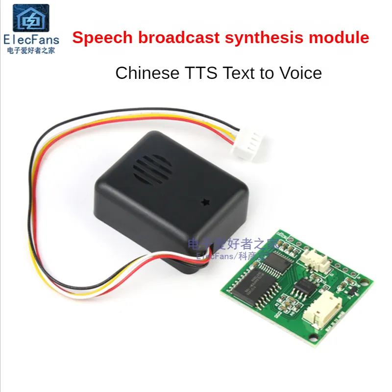
After remarkable success with the SYN-6988 TTS module, then somewhat less success with the SYN-6658 and other modules, I didn’t hold out much hope for the YuTone SYN-6288, which – while boasting a load of background tunes that could play over speech – can only convert Chinese text to speech
The wiring is similar to the SYN-6988: a serial UART connection at 9600 baud, plus a Busy (BY) line to signal when the chip is busy. The serial protocol is slightly more complicated, as the SYN-6288 requires a checksum byte at the end.
As I’m not interested in the text-to-speech output itself, here’s a MicroPython script to play all of the sounds:
# very crude MicroPython demo of SYN6288 TTS chip
# scruss, 2023-07
import machine
import time

### setup device
ser = machine.UART(
    0, baudrate=9600, bits=8, parity=None, stop=1
)  # tx=Pin(0), rx=Pin(1)

busyPin = machine.Pin(2, machine.Pin.IN, machine.Pin.PULL_UP)


def sendspeak(u2, data, busy):
    # modified from https://github.com/TPYBoard/TPYBoard_lib/
    # u2 = UART(uart, baud)
    eec = 0
    buf = [0xFD, 0x00, 0, 0x01, 0x01]
    # buf = [0xFD, 0x00, 0, 0x01, 0x79]  # plays with bg music 15
    buf[2] = len(data) + 3
    buf += list(bytearray(data, "utf-8"))
    for i in range(len(buf)):
        eec ^= int(buf[i])
    buf.append(eec)
    u2.write(bytearray(buf))
    while busy.value() != True:
        # wait for busy line to go high
        time.sleep_ms(5)
    while busy.value() == True:
        # wait for it to finish
        time.sleep_ms(5)


for s in "abcdefghijklmnopqrstuvwxy":
    playstr = "[v10][x1]sound" + s
    print(playstr)
    sendspeak(ser, playstr, busyPin)
    time.sleep(2)

for s in "abcdefgh":
    playstr = "[v10][x1]msg" + s
    print(playstr)
    sendspeak(ser, playstr, busyPin)
    time.sleep(2)

for s in "abcdefghijklmno":
    playstr = "[v10][x1]ring" + s
    print(playstr)
    sendspeak(ser, playstr, busyPin)
    time.sleep(2)
Each sound starts and stops with a very loud click, and the sound quality is not great. I couldn’t get a good recording of the sounds (some of which of which are over a minute long) as the only way I could get reliable audio output was through tiny headphones. Any recording came out hopelessly distorted:
I’m not too disappointed that this didn’t work well. I now know that the SYN-6988 is the good one to get. It also looks like I may never get to try the XFS5152CE speech synthesizer board: AliExpress has cancelled my shipment for no reason. It’s supposed to have some English TTS function, even if quite limited.
Here’s the auto-translated SYN-6288 manual, if you do end up finding a use for the thing
Yup, it’s another “let’s wire up a SYN6988 board” thing, this time for MMBasic running on the Armmite STM32F407 Module (aka ‘Armmite F4’). This board is also known as the BLACK_F407VE, which also makes a nice little MicroPython platform.
Uh, let’s not dwell too much on how the SYN6988 seems to parse 19:51 as “91 minutes to 20” …
Wiring
SYN6988
Armmite F4
RX
PA09 (COM1 TX)
TX
PA10 (COM1 RX)
RDY
PA08
your choice of 3.3 V and GND connections, of course
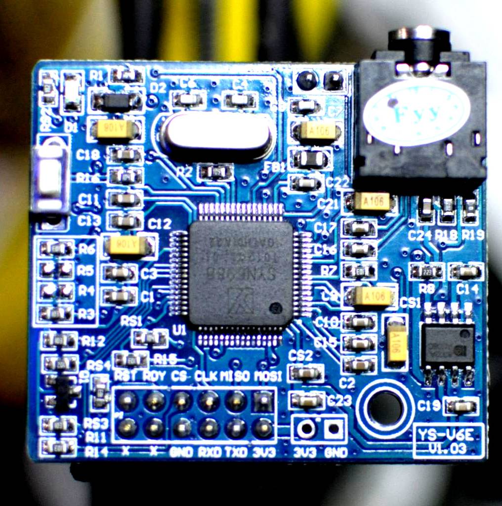
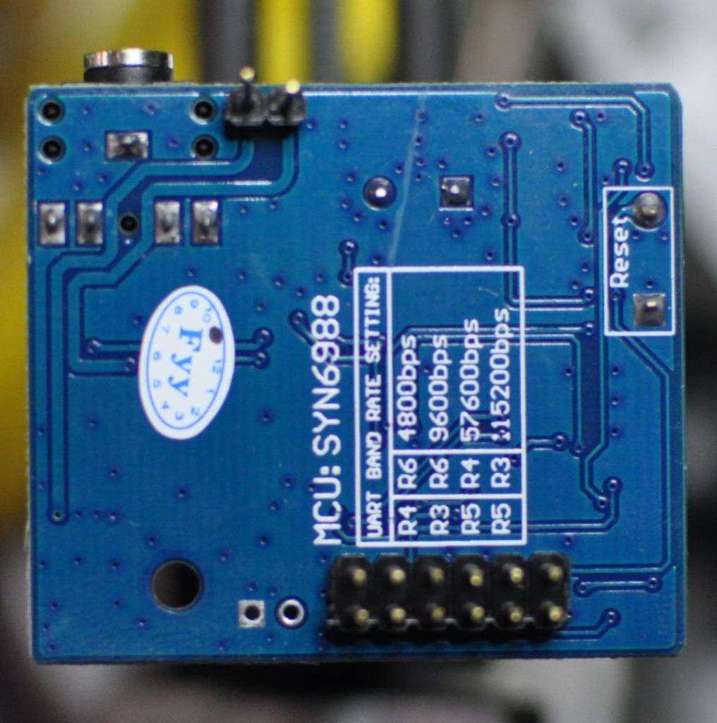
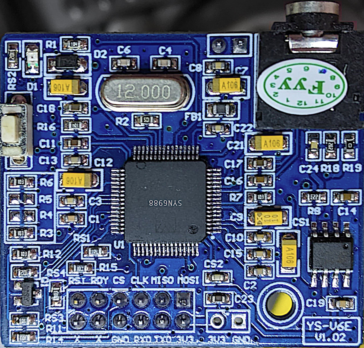
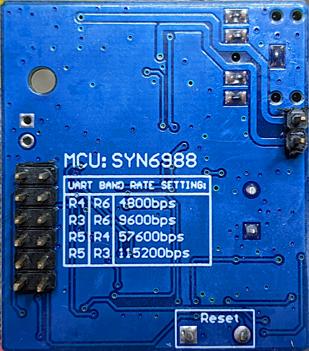
Yes, I know it says it’s an XFS5152, but I got a SYN6988 and it seems to be about as reliable a source as one can find. The board is marked YS-V6E-V1.03, and even mentions SYN6988 on the rear silkscreen:
Code
REM                 SYN6988 speech demo - MMBasic / Armmite F4
REM                 scruss, 2023-07

OPEN "COM1:9600" AS #5
REM                 READY line on PA8
SETPIN PA8, DIN, PULLUP

REM    you can ignore font/text commands
CLS
FONT 1
TEXT 0,15,"[v1]Hello - this is a speech demo."
say("[v1]Hello - this is a speech demo.")
TEXT 0,30,"[x1]soundy[d]"
say("[x1]soundy[d]"): REM    chimes
TEXT 0,45,"The time is "+LEFT$(TIME$,5)+"."
say("The time is "+LEFT$(TIME$,5)+".")
END

SUB say(a$)
  LOCAL dl%,maxlof%
  REM     data length is text length + 2 (for the 1 and 0 bytes)
  dl%=2+LEN(a$)
  maxlof%=LOF(#5)
  REM     SYN6988 simple data packet
  REM      byte  1 : &HFD
  REM      byte  2 : data length (high byte)
  REM      byte  3 : data length (low byte)
  REM      byte  4 : &H01
  REM      byte  5 : &H00
  REM      bytes 6-: ASCII string data
  PRINT #5, CHR$(&hFD)+CHR$(dl%\256)+CHR$(dl% MOD 256)+CHR$(1)+CHR$(0)+a$;
  DO WHILE LOF(#5)<maxlof%
  REM       pause while sending text
    PAUSE 5
  LOOP
  DO WHILE PIN(PA8)<>1
    REM       wait until RDY is high
    PAUSE 5
  LOOP
  DO WHILE PIN(PA8)<>0
    REM       wait until SYN6988 signals READY
    PAUSE 5
  LOOP
END SUB
The other week’s success with the SYN6988 TTS chip was not repeated with three other modules I ordered, alas. Two of them I couldn’t get a peep out of, the other didn’t support English text-to-speech.
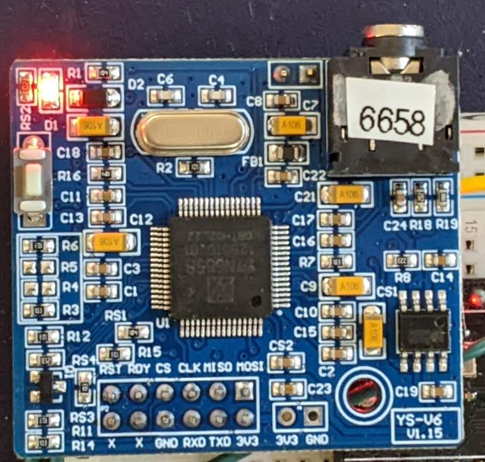
SYN6658
This one looks remarkably like the SYN6988:
Yes, I added the 6658 label so I could tell the boards apart
Apart from the main chip, the only difference appears to be that the board’s silkscreen says YS-V6 V1.15 where the SYN6988’s said YS-V6E V1.02.
To be fair to YuTone (the manufacturer), they claim this only supports Chinese as an input language. If you feed it English, at best you’ll get it spelling out the letters. It does have quite a few amusing sounds, though, so at least you can make it beep and chime. My MicroPython library for the VoiceTX SYN6988 text to speech module can drive it as far as I understand it.
I’ve still got a SYN6288 to look at, plus a XFS5152CE TTSthat’s in the mail that may or may not be in the mail. The SYN6988 is the best of the bunch so far.
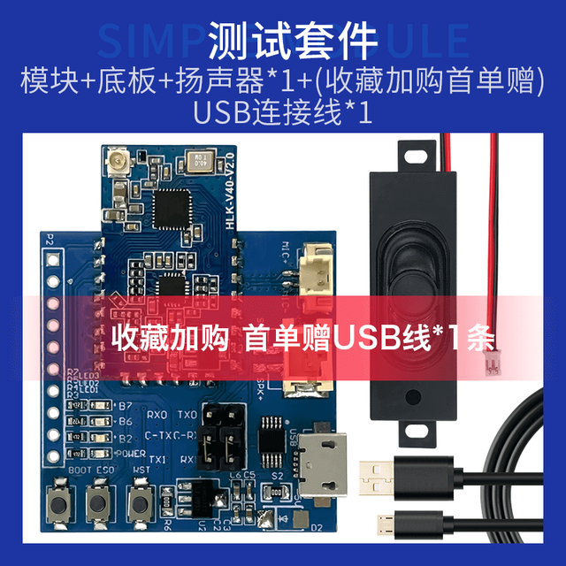
I’ve had one of these cheap(ish – $15) sound modules from AliExpress for a while. I hadn’t managed to get much out of it before, but I poked about at it a little more and found I was trying to drive the wrong chip. Aha! Makes all the difference.
Sensitive listener alert! There is a static click midway through. I edited out the clipped part, but it’s still a little jarring. It would always do this at the same point in playback, for some reason.
The only Pythonish code I could find for these chips was meant for the older SYN6288 and MicroPython (syn6288.py). I have no idea what I’m doing, but with some trivial modification, it makes sound.
I used the simple serial UART connection: RX -> TX, TX -> RX, 3V3 to 3V3 and GND to GND. My board is hard-coded to run at 9600 baud. I used the USB serial adapter that came with the board.
Here’s the code that read that text:
#!/usr/bin/env python3
# -*- coding: utf-8 -*-

import serial
import time

# NB via MicroPython and old too! Also for a SYN6288, which I don't have
# nabbed from https://github.com/TPYBoard/TPYBoard_lib/

def sendspeak(port, data):
    eec = 0
    buf = [0xFD, 0x00, 0, 0x01, 0x01]
    buf[2] = len(data) + 3
    buf += list(bytearray(data, encoding='utf-8'))
    for i in range(len(buf)):
        eec ^= int(buf[i])
    buf.append(eec)
    port.write(bytearray(buf))

ser = serial.Serial("/dev/ttyUSB1", 9600)
sendspeak(ser, "[t5]I like to think [p100](it [t7]has[t5] to be!)[p100] of a cybernetic ecology [p100]where we are free of our labors and joined back to nature, [p100]returned to our mammal brothers and sisters, [p100]and all watched over by machines of loving grace")
time.sleep(8)
ser.close()
This code is bad. All I did was prod stuff until it stopped not working. Since all I have to work from includes a datasheet in Chinese (from here: ??????-SYN6988???TTS????) there’s lots of stuff I could do better. I used the tone and pause tags to give the reading a little more life, but it’s still a bit flat. For $15, though, a board that makes a fair stab at reading English is not bad at all. We can’t all afford vintage DECtalk hardware.
The one thing I didn’t do is used the SYN6988’s Busy/Ready line to see if it was still busy reading. That means I could send it text as soon as it was ready, rather than pausing for 8 seconds after the speech. This refinement will come later, most likely when I port this to MicroPython.
A while back, Seeed Studio sent me one of their Wio Terminal devices to review. It was pretty neat, but being limited to using Arduino to access all of it features was a little limiting. I still liked it, though, and wrote about it here: SeeedStudio Wio Terminal
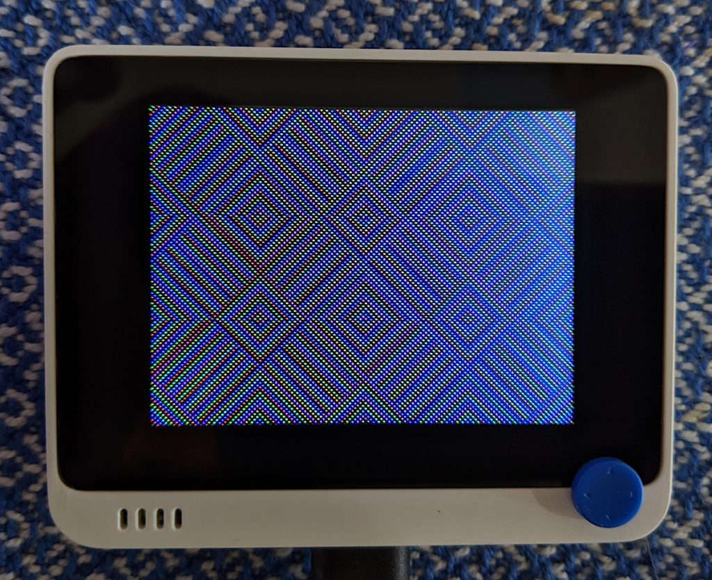
Wio Terminal, doing a thing
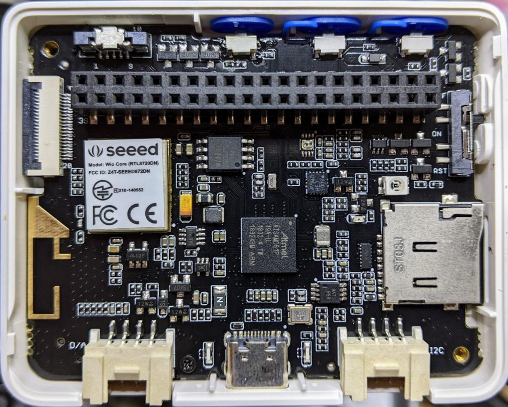
There wasn’t any proper MicroPython support for the device as it used a MicroChip/Atmel SAMD51 ARM® Cortex®-M4 micro-controller. But since I wrote the review, one developer (robert-hh) has worked almost entirely solo to make SAMD51 and SAMD21 support useful in mainline MicroPython.
Hey! Development is still somewhere between “not quite ready for prime time” and “beware of the leopard”. MicroPython on the SAMD51 works remarkably well for supported boards, but don’t expect this to be beginner-friendly yet.
I thought I’d revisit the Wio Terminal and see what I could do using a nightly build (downloaded from Downloads – Wio Terminal D51R – MicroPython). Turns out, most of the board works really well!
What doesn’t work yet
Networking/Bluetooth – this is never going to be easy, especially with Seeed Studio using a separate RTL8720 SoC. It may not be entirely impossible, as previously thought, but so far, wifi support seems quite far away
RTC – this is a compile-time option, but isn’t available on the stock images. Not all SAMD51 boards have a separate RTC oscillator, and deriving the RTC from the system oscillator would be quite wobbly. RTC works now! It may even be possible to provide backup battery power and have it keep time when powered off. VBAT / PB03 / SPI_SCK is broken out to the 40-pin connector.
What does work
Display – ILI9341 320×240 px, RGB565 via SPI
Accelerometer – LIS3DHTR via I²C
Microphone – analogue
Speaker – more like a buzzer, but this little PWM speaker element does allow you to play sounds
Light Sensor – via analogue photo diode
IR emitter – PWM, not tied to any hardware protocol
Internal LED – a rather faint blue thing, but useful for low-key signalling
Micro SD Card – vi SPI. Works well with MicroPython’s built-in virtual file systems
Switches and buttons – three buttons on the top, and a five-way mini-joystick
I²C via Grove Connector – a second, separate I²C channel.
I’ll go through each of these here, complete with a small working example.
Inside the remarkably hard-to-open Wio Terminal
LED
Let’s start with the simplest feature: the tiny blue LED hidden inside the case. You can barely see this, but it glows out around the USB C connector on the bottom of the case.
MicroPython interfaces: machine.Pin, machine.PWM
Control pin: Pin(“LED_BLUE”) or Pin(15), or Pin(“PA15”): any one of these would work.
# MicroPython / Seeed Wio Terminal / SAMD51
# Wio-Terminal-LED.py - blink the internal blue LED
# scruss, 2022-10
# -*- coding: utf-8 -*-

from machine import Pin
from time import sleep_ms

led = Pin("LED_BLUE", Pin.OUT)  # or Pin(15) or Pin("PA15")

try:
    while True:
        led.value(not led.value())
        sleep_ms(1200)
except:
    led.value(0)  # turn it off if user quits
    exit()
IR LED
I don’t have any useful applications of the IR LED for device control, so check out Awesome MicroPython’s IR section for a library that would work for you.
# MicroPython / Seeed Wio Terminal / SAMD51
# Wio-Terminal-IR_LED.py - blink the internal IR LED
# scruss, 2022-10
# -*- coding: utf-8 -*-

# Hey! This is a completely futile exercise, unless you're able
# to see into the IR spectrum. But we're here to show you the pin
# specification to use. For actual useful libraries to do stuff with
# IR, take a look on https://awesome-micropython.com/#ir

# So this is a boring blink, 'cos we're keeping it short here.
# You might be able to see the LED (faintly) with your phone camera

from machine import Pin, PWM
from time import sleep_ms

ir = PWM(Pin("PB31"))  # "IR_CTL" not currently defined

try:
    while True:
        ir.duty_u16(32767)  # 50% duty
        ir.freq(38000)  # fast flicker
        sleep_ms(1200)
        ir.duty_u16(0)  # off
        sleep_ms(1200)
except:
    ir.duty_u16(0)  # turn it off if user quits
    exit()
Buttons
There are three buttons on top, plus a 5-way joystick on the front. Their logic is inverted, so they read 0 when pressed, 1 when not. It’s probably best to use machine.Signal with these to make operation more, well, logical.
Control pins: Pin(“BUTTON_3”) or Pin(92) or Pin(PC28) – top left; Pin(“BUTTON_2”) or Pin(91) or Pin(PC27) – top middle; Pin(“BUTTON_1”) or Pin(90) or Pin(PC26) – top right; Pin(“SWITCH_B”) or Pin(108) or Pin(PD12) – joystick left; Pin(“SWITCH_Y”) or Pin(105) or Pin(PD09) – joystick right; Pin(“SWITCH_U”) or Pin(116) or Pin(PD20) – joystick up; Pin(“SWITCH_X”) or Pin(104) or Pin(PD08) – joystick down; Pin(“SWITCH_Z”) or Pin(106) or Pin(PD10) – joystick button
# MicroPython / Seeed Wio Terminal / SAMD51
# Wio-Terminal-Buttons.py - test the buttons
# scruss, 2022-10
# -*- coding: utf-8 -*-

# using Signal because button sense is inverted: 1 = off, 0 = on
from machine import Pin, Signal
from time import sleep_ms

pin_names = [
    "BUTTON_3",  # Pin(92)  or Pin(PC28) - top left
    "BUTTON_2",  # Pin(91)  or Pin(PC27) - top middle
    "BUTTON_1",  # Pin(90)  or Pin(PC26) - top right
    "SWITCH_B",  # Pin(108) or Pin(PD12) - joystick left
    "SWITCH_Y",  # Pin(105) or Pin(PD09) - joystick right
    "SWITCH_U",  # Pin(116) or Pin(PD20) - joystick up
    "SWITCH_X",  # Pin(104) or Pin(PD08) - joystick down
    "SWITCH_Z",  # Pin(106) or Pin(PD10) - joystick button
]

pins = [None] * len(pin_names)
for i, name in enumerate(pin_names):
    pins[i] = Signal(Pin(name, Pin.IN), invert=True)

while True:
    for i in range(len(pin_names)):
        print(pins[i].value(), end="")
    print()
    sleep_ms(100)
Buzzer
A very quiet little PWM speaker.
MicroPython interfaces: machine.PWM
Control pin: Pin(“BUZZER”) or Pin(107) or Pin(“PD11”)
# MicroPython / Seeed Wio Terminal / SAMD51
# Wio-Terminal-Microphone.py - print values from the microphone
# scruss, 2022-10
# -*- coding: utf-8 -*-

from time import sleep_ms
from machine import ADC

mic = ADC("MIC")

while True:
    print([mic.read_u16()])
    sleep_ms(5)
Grove I²C Port
The Wio Terminal has two Grove ports: the one on the left (under the speaker port) is an I²C port. As I don’t know what you’ll be plugging in there, this example does a simple bus scan. You could make a, appalling typewriter if you really wanted.
# MicroPython / Seeed Wio Terminal / SAMD51
# Wio-Terminal-Grove-I2C.py - show how to connect on Grove I2C
# scruss, 2022-10
# -*- coding: utf-8 -*-

from machine import Pin, I2C

# NB: This doesn't do much of anything except list what's
# connected to the left (I²C) Grove connector on the Wio Terminal

i2c = I2C(3, scl=Pin("SCL1"), sda=Pin("SDA1"))
devices = i2c.scan()

if len(devices) == 0:
    print("No I²C devices connected to Grove port.")
else:
    print("Found these I²C devices on the Grove port:")
    for n, id in enumerate(devices):
        print(" device", n, ": ID", id, "(hex:", hex(id) + ")")
LIS3DH Accelerometer
This is also an I²C device, but connected to a different port (both logically and physically) than the Grove one.
Library: from MicroPython-LIS3DH, copy lis3dh.py to the Wio Terminal’s small file system. Better yet, compile it to mpy using mpy-cross to save even more space before you copy it across
# MicroPython / Seeed Wio Terminal / SAMD51
# Wio-Terminal-Accelerometer.py - test out accelerometer
# scruss, 2022-10
# -*- coding: utf-8 -*-
# based on
#  https://github.com/tinypico/tinypico-micropython/tree/master/lis3dh%20library

import lis3dh, time, math
from machine import Pin, I2C

i2c = I2C(4, scl=Pin("SCL0"), sda=Pin("SDA0"))
imu = lis3dh.LIS3DH_I2C(i2c)

last_convert_time = 0
convert_interval = 100  # ms
pitch = 0
roll = 0

# Convert acceleration to Pitch and Roll
def convert_accell_rotation(vec):
    x_Buff = vec[0]  # x
    y_Buff = vec[1]  # y
    z_Buff = vec[2]  # z

    global last_convert_time, convert_interval, roll, pitch

    # We only want to re-process the values every 100 ms
    if last_convert_time < time.ticks_ms():
        last_convert_time = time.ticks_ms() + convert_interval

        roll = math.atan2(y_Buff, z_Buff) * 57.3
        pitch = (
            math.atan2((-x_Buff), math.sqrt(y_Buff * y_Buff + z_Buff * z_Buff)) * 57.3
        )

    # Return the current values in roll and pitch
    return (roll, pitch)


# If we have found the LIS3DH
if imu.device_check():
    # Set range of accelerometer (can be RANGE_2_G, RANGE_4_G, RANGE_8_G or RANGE_16_G).
    imu.range = lis3dh.RANGE_2_G

    # Loop forever printing values
    while True:
        # Read accelerometer values (in m / s ^ 2).  Returns a 3-tuple of x, y,
        # z axis values.  Divide them by 9.806 to convert to Gs.
        x, y, z = [value / lis3dh.STANDARD_GRAVITY for value in imu.acceleration]
        print("x = %0.3f G, y = %0.3f G, z = %0.3f G" % (x, y, z))

        # Convert acceleration to Pitch and Roll and print values
        p, r = convert_accell_rotation(imu.acceleration)
        print("pitch = %0.2f, roll = %0.2f" % (p, r))

        # Small delay to keep things responsive but give time for interrupt processing.
        time.sleep(0.1)
Control Pins: Pin(“SD_SCK”), Pin(“SD_MOSI”), Pin(“SD_MISO”) for SD access. Pin(“SD_DET”) is low if an SD card is inserted, otherwise high
Library: copy sdcard.py from micropython-lib to the Wio Terminal’s file system.
Rather than provide a small canned example (there’s one here, if you must: Wio-Terminal-SDCard.py) here’s my boot.py startup file, showing how I safely mount an SD card if there’s one inserted, but keep booting even if it’s missing:
# boot.py - MicroPython / Seeed Wio Terminal / SAMD51

import sys

sys.path.append("/lib")

import machine
import gc
import os
import sdcard

machine.freq(160000000)  # fast but slightly jittery clock
gc.enable()

# mount SD card if there's one inserted
try:
    sd_detected = machine.Signal(
        machine.Pin("SD_DET", machine.Pin.IN),
        invert=True,
    )
    sd_spi = machine.SPI(
        6,
        sck=machine.Pin("SD_SCK"),
        mosi=machine.Pin("SD_MOSI"),
        miso=machine.Pin("SD_MISO"),
        baudrate=40000000,
    )
    sd = sdcard.SDCard(sd_spi, machine.Pin("SD_CS"))
    if sd_detected.value() == True:
        os.mount(sd, "/SD")
        print("SD card mounted on /SD")
    else:
        raise Exception("SD card not inserted, can't mount /SD")
except:
    print("SD card not found")
The Wio Terminal may have an XPT2046 resistive touch controller installed, but I haven’t been able to test it. There are LCD_XL, LCD_YU, LCD_XR and LCD_YD lines on the schematic that might indicate it’s there, though.
# MicroPython / Seeed Wio Terminal / SAMD51
# Wio-Terminal-Screen.py - output something on the ILI9341 screen
# scruss, 2022-10
# -*- coding: utf-8 -*-


from time import sleep
from ili9341 import Display, color565
from machine import Pin, SPI


def wheel565(pos):
    # Input a value 0 to 255 to get a colour value.
    # The colours are a transition r - g - b - back to r.
    # modified to return RGB565 value for ili9341 - scruss
    (r, g, b) = (0, 0, 0)
    if (pos < 0) or (pos > 255):
        (r, g, b) = (0, 0, 0)
    if pos < 85:
        (r, g, b) = (int(pos * 3), int(255 - (pos * 3)), 0)
    elif pos < 170:
        pos -= 85
        (r, g, b) = (int(255 - pos * 3), 0, int(pos * 3))
    else:
        pos -= 170
        (r, g, b) = (0, int(pos * 3), int(255 - pos * 3))
    return (r & 0xF8) << 8 | (g & 0xFC) << 3 | b >> 3


# screen can be a little slow to turn on, so use built-in
# LED to signal all is well
led = Pin("LED_BLUE", Pin.OUT)

backlight = Pin("LED_LCD", Pin.OUT)  # backlight is not a PWM pin
spi = SPI(
    7, sck=Pin("LCD_SCK"), mosi=Pin("LCD_MOSI"), miso=Pin("LCD_MISO"), baudrate=4000000
)
display = Display(spi, dc=Pin("LCD_D/C"), cs=Pin("LCD_CS"), rst=Pin("LCD_RESET"))
display.display_on()
display.clear()
led.on()  # shotgun debugging, embedded style
backlight.on()

# use default portrait settings: x = 0..239, y = 0..319
dx = 3
dy = 4
x = 3
y = 4
i = 0

try:
    while True:
        # display.draw_pixel(x, y, wheel565(i))
        display.fill_hrect(x, y, 3, 4, wheel565(i))
        i = (i + 1) % 256
        x = x + dx
        y = y + dy
        if x <= 4:
            dx = -dx
        if x >= 234:
            dx = -dx
        if y <= 5:
            dy = -dy
        if y >= 313:
            dy = -dy
except:
    backlight.off()
    led.off()
    display.display_off()
More Micropython programmers — and especially beginners — should know about Awesome MicroPython. It’s a community-curated list of remarkably decent MicroPython libraries, frameworks, software and resources. If you need to interface to a sensor, look there first.
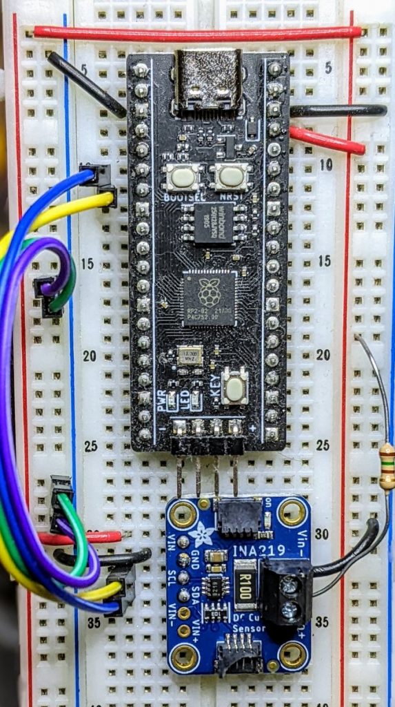
For example, take the INA219 High Side DC Current Sensor. It’s an I²C sensor able to measure up to 26 V, ±3.2 A. It does this by measuring the voltage across a 0.1 ohm precision shunt resistor with its built-in 12-bit ADC. I got a customer return from the store that was cosmetically damaged but still usable, so I thought I’d try it with the simplest module I could find in Awesome MicroPython and see how well it worked.
I guess I needed a test circuit too. Using all of what was immediately handy — a resistor I found on the bench and measured at 150.2 ohm — I came up with this barely useful circuit:
Should indicate a current of 3.3 / (150.2 + 0.1) = 21.96 mA
The INA219 would be happier with a much higher current to measure, but I didn’t have anything handy that could do that.
Looking in Awesome MicroPython’s Current section, I found robert-hh/INA219: INA219 Micropython driver. It doesn’t have much (okay, any) documentation, but it’s a very small module and the code is easy enough to follow. I put the ina219.py module file into the /lib folder of a WeAct Studio RP2040 board, and wrote the following code:
# INA219 demo - uses https://github.com/robert-hh/INA219

from machine import Pin, I2C
import ina219

i = I2C(0, scl=Pin(5), sda=Pin(4))
print("I2C Bus Scan: ", i.scan(), "\n")

sensor = ina219.INA219(i)
sensor.set_calibration_16V_400mA()

# my test circuit is 3V3 supply through 150.2 ohm resistor
r_1 = 150.2
r_s = 0.1  # shunt resistor on INA219 board

# current is returned in milliamps
print("Current       / mA: %8.3f" % (sensor.current))
# shunt_voltage is returned in volts
print("Shunt voltage / mV: %8.3f" % (sensor.shunt_voltage * 1000))
# estimate supply voltage from known resistance * sensed current
print("3V3 (sensed)  / mV: %8.3f" % ((r_1 + r_s) * sensor.current))
with everything wired up like this (Blue = SDA, Yellow = SCL):
all of the wires
Running it produced this:
I2C Bus Scan:  [64]

Current       / mA:   22.100
Shunt voltage / mV:    2.210
3V3 (sensed)  / mV: 3321.630
So it’s showing just over 22 mA: pretty close to what I calculated!

