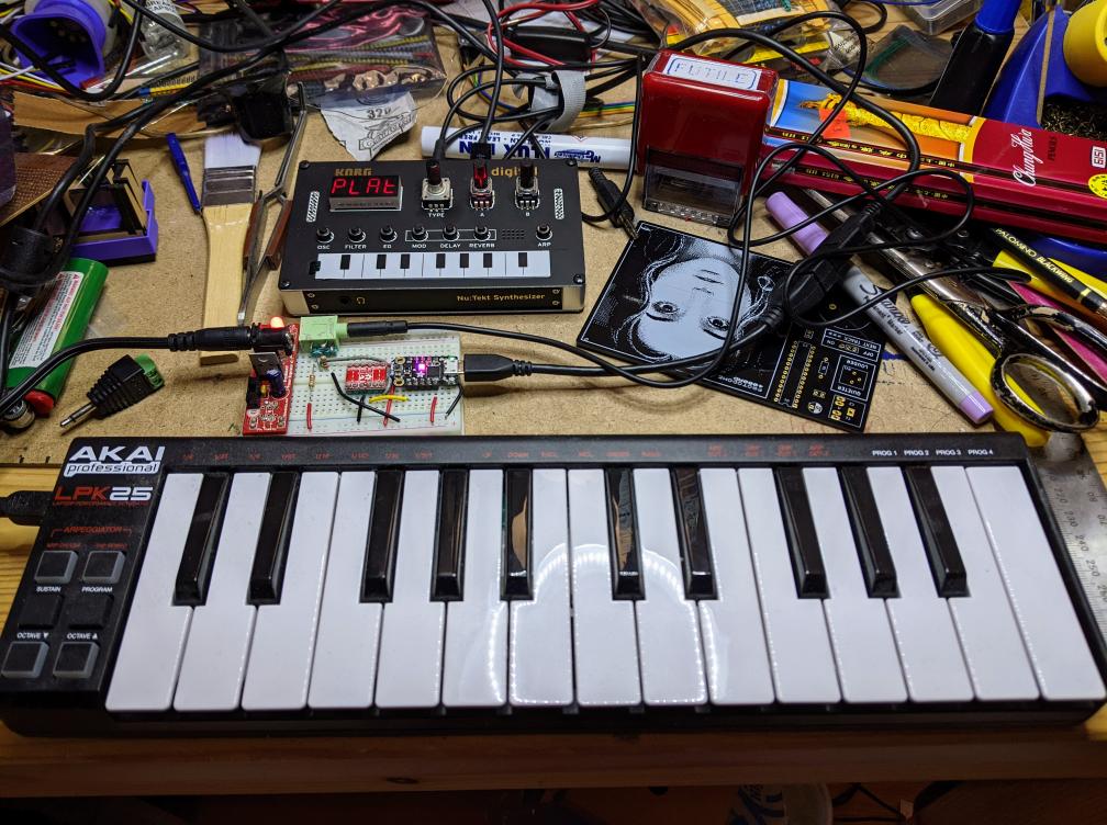
Akai LPK25 keyboard has USB MIDI out, but the Korg NTS-1 only has regular MIDI in. The little board in the middle acts as a USB host for the Akai and MIDI source for the Korg
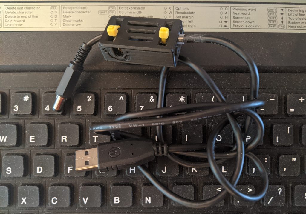
my Z88 – USB power cable, with slightly stoory Z88 underneath
I got a Cambridge Computer Z88 again, after perhaps 30 years of not having one. They are very nice little portable computers, remarkable for packing a multi-tasking OS into an 8-bit machine that runs for weeks on 4x AA batteries.
But the Z88 is a Clive Sinclair joint, so there’s going to be at least one deeply weird and/or ill-advised detail about it. For me, it’s the power adapter. The original had a 6 V centre-positive barrel connector, but in true Sinclair fashion, that wasn’t quite ideal.
The DC power comes through a diode, which drops it down to ~5.2 V. The batteries supply up to 6 V and there’s no protection circuit, so the DC adapter won’t do anything until the internal batteries discharge down to that level. This is far from ideal.
The clever way of dealing with this was Rakewell’s Z88 PSU. This was a variable voltage PSU set to deliver 7 V, so that even when dropped through the power diode, it wouldn’t deplete the batteries.
Unfortunately, Rakewell stopped selling these a while ago. But I remembered I had a some MT3608 (datasheet) boards bought at a hamfest some years back. MT3608s are boost DC-DC converters, so they’ll convert from a lower DC voltage to a higher one, typically at least +2 V higher than the input. With a hacked-up USB cable, a small length of DC cable with a connector and a 3d printed case, I built one that works quite well, at least in the short time I’ve tested it.
Newer MT3608 boards sometimes feature a micro-USB connector, which is much more convenient than hacking up a USB cable
It’s really important to know how to adjust a MT3608 DC-DC Booster before connecting the final voltage, as it’s very easy to burn the board out
You can’t use a computer USB port to power an MT3608, as the cable’s not smart enough to negotiate a decent amount of current. A good phone charger should be enough.
I set the voltage output to be 7.05 V, with no load
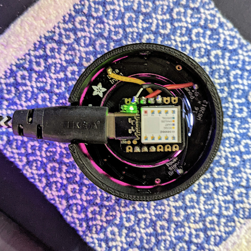
Slightly blurry image of the underside of the device, showing the Seeeduino XIAO and the glow from the NeoPixel ring. And yes, the XIAO is really that small
The QT Py is based on the Seeeduino XIAO, which is a slightly simpler device than the Adafruit derivative. It still runs CircuitPython, though, and is about the least expensive way of doing so. The XIAO is drop-in replacement for the Qt Py in this project, and it works really well! Everything you need for the project is described here: todbot/qtpy-knob: QT Py Media Knob using rotary encoder & neopixel ring
I found a couple of tiny glitches in the 3d printed parts, though:
The diffuser ring for the LED ring is too thick for the encoder lock nut to fasten. It’s 2 mm thick, and there’s exactly 2 mm of thread left on the encoder.
The D-shaft cutout in the top is too deep to allow the encoder shaft switch to trigger.
I bodged these by putting an indent in the middle of the diffuser, and filling the top D-shaft cutout with just enough Blu Tack.
Tod’s got a bunch of other projects for the Qt Py that I’m sure would work well with the XIAO: QT Py Tricks. And yes, there’s an “Output Farty Noises to DAC†one that, regrettably, does just that.
Maybe I’ll add some mass to the dial to make it scroll more smoothly like those buttery shuttle dials from old video editing consoles. The base could use a bit more weight to stop it skiting about the desk, so maybe I’ll use Vik’s trick of embedding BB gun shot into hot glue. For now, I’ve put some rubber feet on it, and it mostly stays put.
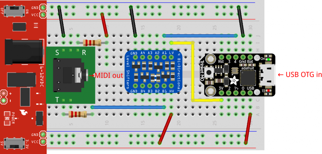
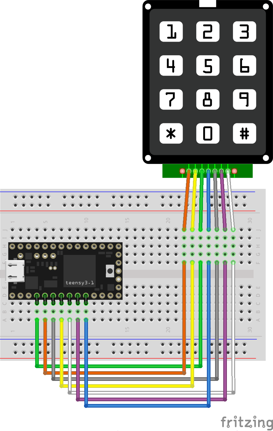
in which I finally learn about Fritzing’s wire alignment facility …
I’ve had a couple of Teensy boards for a while, but a misunderstanding that they needed a load of of extra software installed (they need one thing, and it’s easy) had kept me away. They’ve got really impressive specs, and they’re especially easy to turn into USB devices like keyboards.
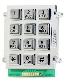
Super-heavy CEECO keypad
Here’s a little demo that turns a phone keypad — in my case, a ridiculously solid CEECO solid metal keypad designed for institutional use — into a simple USB keyboard. Plug it into any machine (including a Raspberry Pi) and it will be identified as a keyboard. No drivers are required.
The code is based on the standard Arduino Keypad library basic demo. That code was meant for a different keypad, so I eventually found a configuration that worked in the Sparkfun 12 button keypaddatasheet. Rather than printing characters to the serial port, I used calls to Teensy’s USB Keyboard library instead.
The pinout is (from left to right, key side up):
do not connect
Column 2
Row 1
Column 1
Row 4
Column 3
Row 3
Row 2
n/c
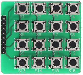
There’s no reason why this wouldn’t work with those very cheap 4×4 button matrix keypads for Arduino too with only minor modifications. Those keypads use 8 data lines, and they’re arranged (I think) as rows 1-4 on pins 1-4 and columns 1-4 are pins 5-8. columns 4-1 then rows 1-4 from the top of the pin connector down:
The Teensy USB keyboard isn’t limited to sending single characters: a single button press could trigger sending a whole string. I haven’t yet thought out any major uses for this (except “Crypto!â€, which is my usual idea when I have no idea what I’m doing), but you might have better plans.
The Raspberry Pi Zero can be set up to appear as one of several USB OTG “gadgets†if you plug it into another computer. The most popular setting seems to be the virtual network gadget that turns your Zero into a computer on the end of your USB cable. Andrew Mulholland’s guide Raspberry Pi Zero – Programming over USB! (Part 2) (along with his super-short simple guide) seems to be the definitive source on how to set these modes up.
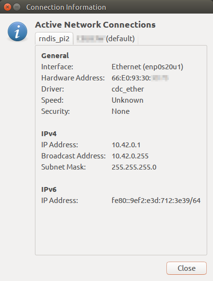
One problem, though, is that the Zero would show up on different network addresses every time it was restarted. The changing addresses made ssh access no fun at all. A suggestion on the Raspberry Pi forum helped me come up with a solution. On the Raspberry Pi Zero, run this command once:
This will set the USB port’s hardware addresses to a fixed value, and you should always get a connection on the same IP address if it’s available.
How my Raspberry Pi Zero appears on my Ubuntu machine
Update: For some reason, this seemed to stop working, and I was getting the old random addresses again. I was resisting putting more stuff in /boot/cmdline.txt, but it seems to me it’s more reliable than what I proposed. So if your g_ether.conf looked like:
This might be my last post on mini-printers, as I’ve found a driver that just works with CUPS on Raspberry Pi. It also works on Ubuntu on my laptop, and should work (though untried) on Mac OS. You’ll have to build it from source, but it’s not too hard.
The hard part is working out if your thermal printer will work or not. There are many out there, and they’re all slightly different. If they support the ESC/POS bitmap command GS v 0 on 58 mm wide paper, they should work. The ones I’ve tested are:
Catex POS5890U — USB, cheap, fast.
“701” control board panel printer — fairly generic, decent quality printer with serial input. A bit slow for daily use at 9600 baud.
Xiamen Embedded Printer DP-EH600 — as above.
The following should also work, but haven’t been tried:
Sparkfun thermal printer — which now appears to be identical to the Adafruit unit, and is referred to as the “A1 (or A2) micro panel printer” in the documentation.
Known not to work:
BTHT-V6 printer — which uses a completely different command set. (Roughly that of an Epson FX-80 for image commands, if you care.)
If you have a manual for your printer, check it to see if it prints bitmaps by sending a three byte header of 29 118 48 (or 1D 76 30 in hexadecimal). If you’re not sure, try it with a small test image, and be ready by the power switch …
Getting and building the driver
The driver is meant for a ZiJiang ZJ-58 printer, and lives here on Github: klirichek/zj-58.
Now read and follow the Building & Installing section of the README, and do what it says. I’ll wait …
Setting up the printer
This bit is much more graphical. You’ll need the system-config-printer package:
sudo apt install -y system-config-printer cups
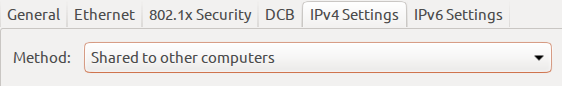
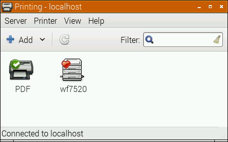
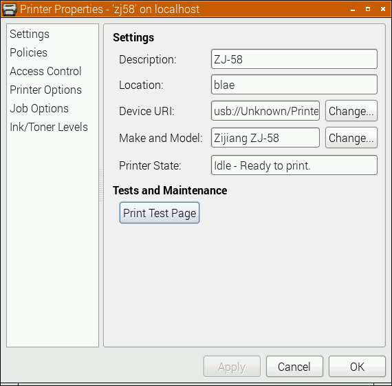
Open up the printer settings window (Preferences → Print Settings):
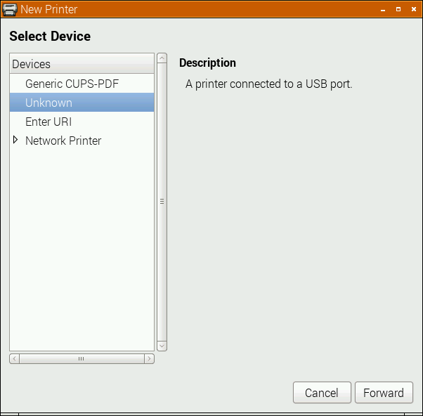
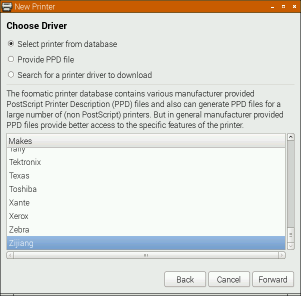
Select the Add icon, and the New Printer window opens:
The POS5890U shows up as “Unknown” on my USB port, as Linux doesn’t know the name of this device from its USB ID.
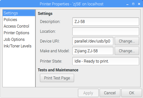
Update (for the slightly desperate): In the land of “Things have changed!“, my Catex printer isn’t/wasn’t showing up at all. I had to resort to this in the Enter URI option:
(hey, this image doesn’t quite match the flow. Look only at the the Device URI bit please)
parallel:/dev/usb/lp0 seems to work. Another option might be looking at the output of
sudo /usr/lib/cups/backend/usb
which suggests that usb://Unknown/Printer might work too. (All of this might need to have been preceded by
sudo usermod -a -G lp pi
and a logout or reboot; I did say this was for the slightly desperate …)
If the above doesn’t apply, your printer might have an known ID, or show up as a serial port. Select the right one, and click Forward:
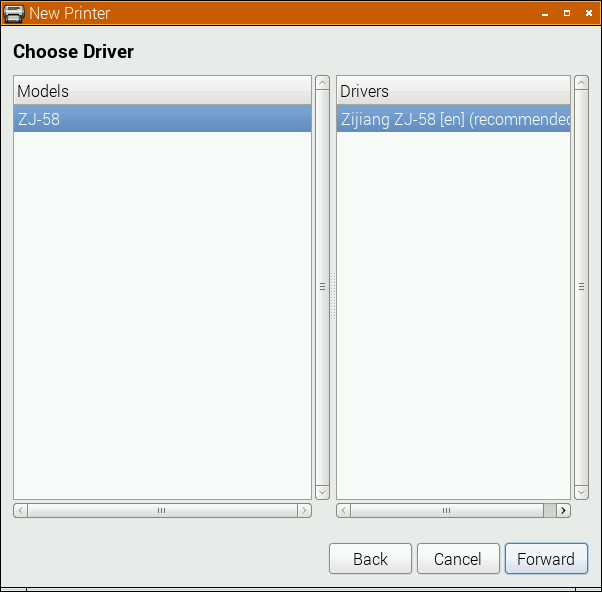
Here, I’m really pleased that the driver is for a Zijiang unit, as it’s conveniently at the end of the list. Click Forward …
No options here, so again, Forward …
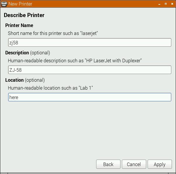
I changed the name from the default ZJ-58 to the more unixly zj58. You don’t have to, but either way, Apply the changes.
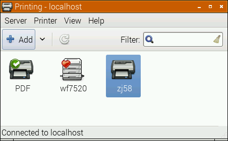
And there it is, registered as a printer!
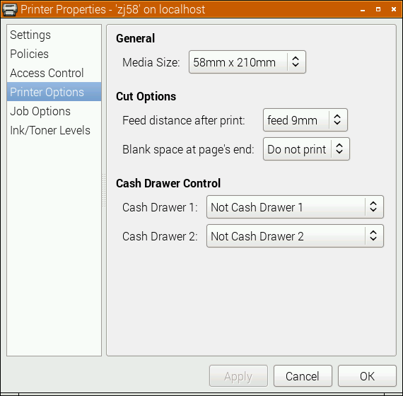
Printer Options
Most printers expect paper wider than 58 mm, but mini-printers can’t do that. To tell the system about paper sizes, right click on the printer’s icon, and change the printer settings:
A test page might print properly now, but you should probably go into Printer Options first:
You do want to set the media size to at least 58 × 210 mm. This is just the longest strip it will print in one ‘page’; if your print is shorter, it won’t waste extra paper. You can choose longer prints, but not wider. The default assume your local standard paper size which —be it A4, Letter, or whatever — will not be what you want here. Hit OK.
Printing something
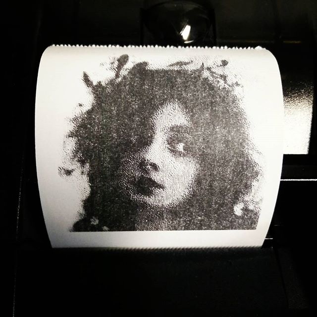
You could print the self test page, but it’s long and boring. If you’re fairly sure your printer will be supported, try this scaled PDF version of the Raspberry Pi Logo: raspberry-pi-logo. Printed and scanned, it came out like this:
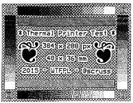
Not the best rendition, but not bad for a $30 receipt printer. My test image came out like this (iffy scan, sorry):
I haven’t covered the intricacies of setting up serial port connections here; maybe another time. Also, there’s a short delay (maybe 10–20 s) between selecting Print and the printer coming to life. CUPS is pretty complex, and is doing things in the background while you wait.
(Seeing as I use their logo prominently up there, I should totes acknowledge that “Raspberry Pi is a trademark of the Raspberry Pi Foundation”. Also, I couldn’t have done all this without the support of Reed Zhao. Though Reed has moved on to bigger things and doesn’t sell printers any more, his help — not to mention the generous gift of a couple of printers — was very welcome.)
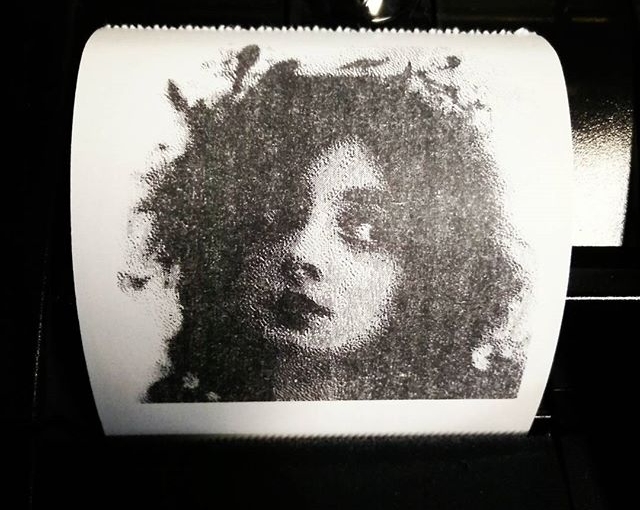
Scored this cheapo USB printer on eBay: “High-speed 58mm POS Dot Receipt Paper Thermal Printer USBâ€. It identifies itself as a CATEX Technolog [sic] POS5890U, with a USB vendor:product ID of b000:0410. After a bit of random fiddling, it shows up as /dev/usb/lp0 on a Raspberry Pi. After turning off CUPS (as it nabs the device, not even letting root near it), you can print images up to 384 dots (48 mm at 8 dots/mm) wide using the ESC-POS GS v 0 command. You can use my esc-pos-image.py script if you wish, and if you need a test image …
(The photo is of Marie Doro; proto-goth 1902 style.)
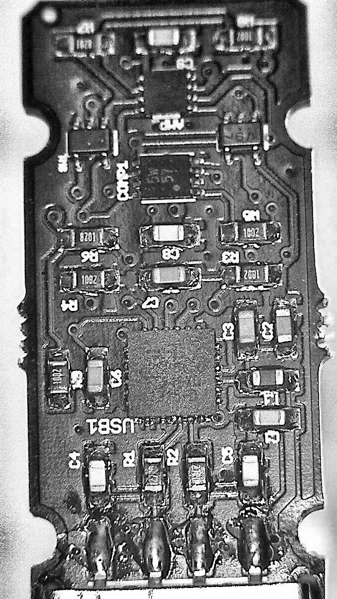
Just got Bill “WaywardGeek” Cox’s Infinite Noise USB Random Number Generator. It uses very few components, and doesn’t even have a microcontroller on board. It relies on the controlled amplification of thermal noise as its entropy source.
Not great enhanced image of the Infinite Noise board. Yes, that’s all there is to it
As it’s so very simple, it uses a driver to read from the device, and then hashes the data to reduce the data stream to very close to pure noise. Building the driver is easy, once you work it that the code lives in the infnoise/software folder on the author’s github repo.
Normal operation would look like this:
sudo ./infnoise | entropy_consuming_program …
as in
sudo ./infnoise | rngtest -t 10
which I left running for a work day to get
…
rngtest: bits received from input: 10327720032
rngtest: FIPS 140-2 successes: 515955
rngtest: FIPS 140-2 failures: 431
rngtest: FIPS 140-2(2001-10-10) Monobit: 63
rngtest: FIPS 140-2(2001-10-10) Poker: 61
rngtest: FIPS 140-2(2001-10-10) Runs: 162
rngtest: FIPS 140-2(2001-10-10) Long run: 151
rngtest: FIPS 140-2(2001-10-10) Continuous run: 0
rngtest: input channel speed: (min=29.022; avg=178.828; max=19531250.000)Kibits/s
rngtest: FIPS tests speed: (min=17.403; avg=30.153; max=85.917)Mibits/s
rngtest: Program run time: 56727702860 microseconds
So from its success to failure rate, it produces pretty decent (for my casual use) results. These bytes chug out at around 22¾ Kbytes/second; not screamingly fast, but decent, considering the very simple hardware.
You can run the hardware without hashing/whitening, and the results (from a much shorter run) are less solid:
sudo ./infnoise --raw | rngtest -t 10
…
rngtest: bits received from input: 15499264
rngtest: FIPS 140-2 successes: 0
rngtest: FIPS 140-2 failures: 774
rngtest: FIPS 140-2(2001-10-10) Monobit: 0
rngtest: FIPS 140-2(2001-10-10) Poker: 774
rngtest: FIPS 140-2(2001-10-10) Runs: 774
rngtest: FIPS 140-2(2001-10-10) Long run: 0
rngtest: FIPS 140-2(2001-10-10) Continuous run: 0
rngtest: input channel speed: (min=27.201; avg=355.760; max=9765625.000)Kibits/s
rngtest: FIPS tests speed: (min=24.868; avg=30.488; max=41.554)Mibits/s
rngtest: Program run time: 49831593 microseconds
Another naïve test is seeing how images made from the data stream look:
random bytes (PNG), file size 49435 bytes
raw bytes (PNG), file size 45421 bytes
Each of these 128 pixel squares should be no less than 49152 (= 128 × 128 × 3) bytes — plus the size of any PNG header/metadata — in size. The fact that the raw output is smaller shows that PNG’s compressor found some patterns it could work with.
It’s a fun little device, and Bill is adding new code and features to the driver at waywardgeek/infnoise regularly.
Over the last few weeks, I’ve been playing with a few small thermal printers. Meant as POS or information booth printers, they make a diverting project for the lo-fi printing enthusiast. While they all have common features — 58 mm/2¼” paper width, 8 pixel/mm resolution, 48 mm print width, serial connection — they all have their quirks. You may have seen these sold as the Adafruit Mini Thermal Receipt Printer or Sparkfun’s Thermal Printer, but there are many others. I’m going to write more on interfacing these directly to Raspberry Pi, Arduino, and (if I can navigate the documentation) a CUPS driver.
For now, I’m just leaving you a list of things I’ve found helpful for the DP-EH600 and 701 printers. Note that the similar-looking BTHT-v6 printer uses a completely different command set.
Replacement paper is sold as 2¼” — 30′. Staples have a box of 30 rolls for under $25 (item 279096, not on their website). Longer rolls don’t fit.
You’ll need a USB→TTL Serial adapter, preferably one with DTR control. I use one from JY-MCU. In a pinch, you can use a simpler Debug / Console Cable for Raspberry Pi, but you risk serial overruns and dodgy results. Remember that RX on the adapter goes to TX on the printer, and vice versa.
A good solid power supply is needed; these printers draw ~8 W when printing. Some printers only support 5 V (for which a 3 amp adapter would be ideal), others 5-9 V. The higher voltage makes text printing faster. You can’t drive these directly from your Raspberry Pi/Arduino power supply.
Linux serial ports are set to some defaults which may have been historically useful, but now corrupt 8-bit data. A trick I picked up here is to first issue the command stty -F /dev/ttyUSB1 0:0:0:0:0:0:0:0:0:0:0:0:0:0:0:0:0:0:0:0:0:0:0:0:0:0:0:0:0:0:0:0:0:0:0:0
which clears all settings, then set the device up as you need it: stty -F /dev/ttyUSB1 speed 9600 raw cs8
(Most of these printers default to 9600 baud. Your device may be called something different to ttyUSB1.)
I’ve written a couple of Python driver stubs which take an image and produce the relevant binary output:
scruss / esc-pos-image.py – prints an image as a single command. May not work on the SparkFun printer. Does not work on the BTHT-v6.
scruss / esc-pos-image-star.py – prints the image in 24 pixel deep bands. Can sometimes cause visible gaps in the printout, but will work on almost all printers, except the BTHT-v6.
These Python libraries also work, as long as you address the printer properly (right device, right speed):
python-escpos – image support limited to 255 pixels high, for some reason.
Reed Zhao (of Tangram Software) lent me a couple of different printers for testing after I bought a different one from him. He’s put a lot of work into sourcing these printers direct from the manufacturers. Thanks, Reed! NB: Reed doesn’t sell printers any more. Try eBay.
BTHT-V6 manual (Chinese) — probably just enough info to follow the wiring and some of the basic control codes. Looks like the one I had was 5V only, so needs a 5V 3A power supply.
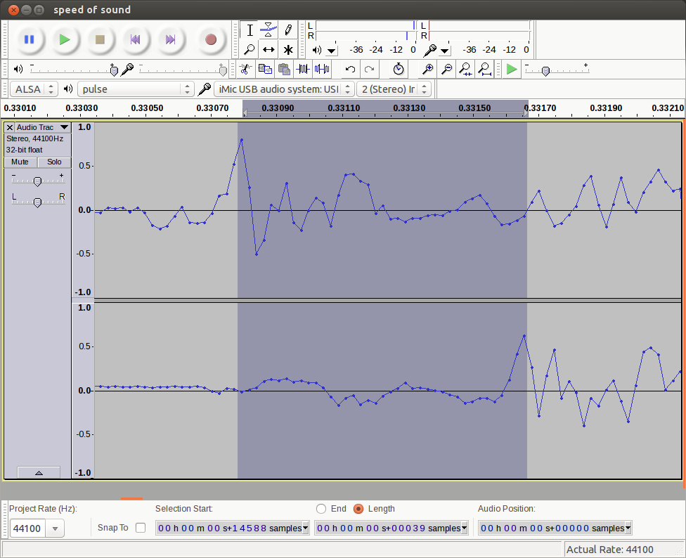
With a pair of binaural mics placed 33.7 cm apart feeding into a stereo USB sound card (a Griffin iMic), I clapped near the left mic. It took 39 samples (884 µs) for the peak to travel between the microphones. That gave me a speed of sound of 381 m/s. A bit high, but the conditions this evening weren’t ideal, and I only set up the experiment with cursory care.
The iMic seems unusual in having a stereo line/mic input. Most other (cheaper) USB dongles only have a mono input.
Hey! This post is completely ancient. It doesn’t even use Python 3. Advice given here might be well out of date.
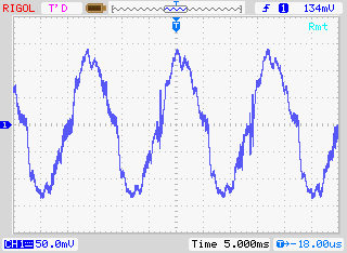
… it complains that the oscilloscope is always making waves.
Ahem. Anyway. I have a Rigol DS1102E 100 MHz Digital Oscilloscope. For such a cheap device, it’s remarkable that you can control it using USB Test & Measurement Class commands. I’d been wanting to use a Raspberry Pi as a headless data acquisition box with the oscilloscope for a while, but Raspbian doesn’t ship with the usbtmc kernel module. I thought I was stuck.
Alex Forencich turned up in the forum with an all-Python solution: Python USBTMC (source: alexforencich / python-usbtmc). I got this working quite nicely today on both the Raspberry Pi and my Ubuntu laptop. Here’s how I installed it:
Check your device’s USB code with lsusb: $ lsusb Bus 001 Device 002: ID 0424:9512 Standard Microsystems Corp. …. Bus 001 Device 004: ID 1ab1:0588 Rigol Technologies DS1000 SERIES
Ensure that libusb-1.0 is installed: sudo apt-get install libusb-1.0-0
Create a new group, usbtmc: sudo groupadd usbtmc
Add yourself to this group: sudo usermod -a -G usbtmc pi
As root, create a file /etc/udev/rules.d/usbtmc.rules. You’ll need to put in your device’s ID values: # USBTMC instruments # Rigol DS1100 – ID 1ab1:0588 Rigol Technologies DS1000 SERIES SUBSYSTEMS==”usb”, ACTION==”add”, ATTRS{idVendor}==”1ab1″, ATTRS{idProduct}==”0588″, GROUP=”usbtmc”, MODE=”0660″
(all of the SUBSYSTEMS to MODE= should be one one line)
Download and install the latest pyusb (Raspbian version is rather old): git clone https://github.com/walac/pyusb.git cd pyusb python setup.py build sudo python setup.py install
Now get python-usbtmc: git clone https://github.com/alexforencich/python-usbtmc.git cd python-usbtmc python setup.py build sudo python setup.py install
For this simple demo, you’ll need to convert the USB vendor IDs to decimal: 0x1ab1 = 6833 0x0588 = 1416
Now, start python as root (sudo python) then type: import usbtmc instr =Â usbtmc.Instrument(6833, 1416) print(instr.ask(“*IDN?”))
This should return something like: Rigol Technologies,DS1102E,DS1EB13490xxxx,00.02.06.00.01
If you get the status line, congratulations! You now have a fully working usbtmc link. I haven’t had much time to play with this, but I know I can make really nice screenshots to an attached USB drive using the command: instr.write(“:HARDcopy”). Many more commands can be found in the DS1000D/E Programming Guide, available on Rigol‘s site.
I had a couple of problems, though:
The library seems to need root privileges, despite the udev rule thing. After creating the udev rule, you will need to reboot. This is the simplest way of getting it to work without being root.
Reading from the ‘scope’s memory chokes on non-UTF8 characters. If I do: rawdata = instr.ask(“:WAV:DATA? CHAN1”)[10:] I get a lengthy Python error which ends: … File “/usr/lib/python2.7/encodings/utf_8.py”, line 16, in decode    return codecs.utf_8_decode(input, errors, True) UnicodeDecodeError: ‘utf8’ codec can’t decode byte 0x99 in position 10: invalid start byte I have no idea what that means, or how to fix it. Alex suggested using ask_raw instead of ask, and the data comes through with no complaints.
I’ve still got to work my way through the Rigol’s data format, but other people have done that before:
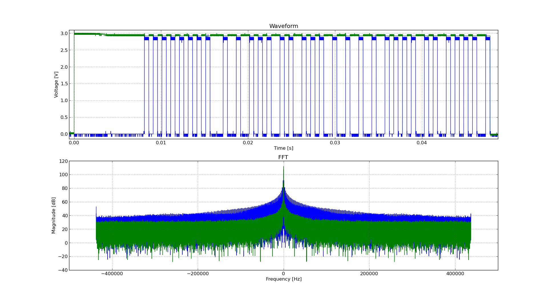
Incidentally, if you’re working with WFM data dumps from the Rigol ‘scopes (and you should, because they make storing data to USB drives quick), mabl/pyRigolWFM is basically magic. Not merely can it describe and decode those binary files, it can do pretty graphics with no thought required:
Update, 2013-12-20: I’ve successfully managed to run most of Ken’s examples with Alex’s code. The major modification you have to do is use ask_raw instead of ask. Example code shown below:
#!/usr/bin/python
# -*- coding: utf-8 -*-

"""
Download data from a Rigol DS1102E oscilloscope and graph with matplotlib
         using  Alex Forencich's python-usbtmc pure python driver
                https://github.com/alexforencich/python-usbtmc
scruss - 2013-12-20

based on
Download data from a Rigol DS1052E oscilloscope and graph with matplotlib.
By Ken Shirriff, http://righto.com/rigol

which in turn was
Based on http://www.cibomahto.com/2010/04/controlling-a-rigol-oscilloscope-using-linux-and-python/
by Cibo Mahto.
"""

import usbtmc
import time
import numpy
import matplotlib.pyplot as plot

# initialise device
instr =  usbtmc.Instrument(0x1ab1, 0x0588) # Rigol DS1102E

# read data
instr.write(":STOP")
instr.write(":WAV:POIN:MODE RAW")
# first ten bytes are header, so skip
rawdata = instr.ask_raw(":WAV:DATA? CHAN1")[10:]
data_size = len(rawdata)

# get metadata
sample_rate = float(instr.ask_raw(':ACQ:SAMP?'))
timescale = float(instr.ask_raw(":TIM:SCAL?"))
timeoffset = float(instr.ask_raw(":TIM:OFFS?"))
voltscale = float(instr.ask_raw(':CHAN1:SCAL?'))
voltoffset = float(instr.ask_raw(":CHAN1:OFFS?"))

# show metadata
print "Data size:      ", data_size
print "Sample rate:    ", sample_rate
print "Time scale:     ", timescale
print "Time offset:    ", timeoffset
print "Voltage offset: ", voltoffset
print "Voltage scale:  ", voltscale

# convert data from (inverted) bytes to an array of scaled floats
# this magic from Matthew Mets
data = numpy.frombuffer(rawdata, 'B')
data = data * -1 + 255
data = (data - 130.0 - voltoffset/voltscale*25) / 25 * voltscale

# creat array of matching timestamps
time = numpy.linspace(timeoffset - 6 * timescale, timeoffset + 6 * timescale,
                      num=len(data))

# scale time series and label accordingly
if (time[-1] < 1e-3):
    time = time * 1e6
    tUnit = "µS"
elif (time[-1] < 1):
    time = time * 1e3
    tUnit = "mS"
else:
    tUnit = "S"

# Plot the data
plot.plot(time, data)
plot.title("Oscilloscope Channel 1")
plot.ylabel("Voltage (V)")
plot.xlabel("Time (" + tUnit + ")")
plot.xlim(time[0], time[-1])
plot.show()
It is a truth universally acknowledged, that an engineer in possession of a solid-state flammable gas detector, will shortly make a fart detector with it. I’m sorry, but call it childishness, simple-minded curiosity, or the results of a diet high in polysaccharides, but this is something I have to get out of my system. (It’s okay; I’ll waft the door.)
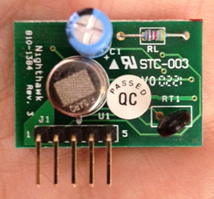
This all started when our carbon monoxide detector decided it was past its best, and started to emit an ear-splitting shriek. Thinking there might be some cool parts inside, I took it apart. Inside, in amongst the other stuff, I found this:
Thankfully, David Cook of Robot Room had once had the same idea as me (well, minus the puerile bits), and he documented the sensor board very well: Explosive Gas Detector Board. Here are the four pins that you really need to get the thing going:
Pins 2 and 3 are active low signals. To be typographically correct, I’d write them as Enable and Gas, but that’s hard to do in fixed-pitch ASCII. I can understand why the Gas signal should be active low (think about it; if the Figaro TGS 2611 sensor fails or shorts, it will likely fail to an alarm state, so you’ll still be alive to curse the bloody noise that woke you at 03h00), but the Enable being active low? Dunno.
I was hoping to have presented a little sketch for the Digispark that would have typed something unhelpful every time that gas was detected, but it was not to be. It seems that Macs and Digispark keyboard emulation is a thing of great wobbliness, so I had to resort to an Arduino and a serial connection.
Here’s the code:
/*
 gas_detector - uses board scavenged from CO detector

 scruss - 2013-02-18 (unfortunately)
 */

int gas     = 2;               // /Gas line on pin 2
int val     = 0;
int lastval = 0;

void setup() {
  pinMode(gas, INPUT);
  Serial.begin(115200);
}

void loop() {
  val = digitalRead(gas);
  if (val != lastval) {
    if (val == LOW) {          // LOW means gas detected
      Serial.println("gas");
      Serial.println();
      delay(1000);             // wait 1s for air to clear
    }
  }
  lastval = val;
}
Before you ask, I tested the circuit by briefly hitting the button on a gas lighter. Honest.
I’ll keep working on the Digispark; it’s such a nifty little device, and this is such a worthy project …
The Raspberry Pi’s hardware and software support has come a long way in the few months it has been in the wild. I first tried this application in the summer, and the results were dismal. Now, thanks much improved USB driver support under Raspbian, I’m pleased to say it works flawlessly.
Earlier this year, I bought a turntable (ack!) for transferring vinyl to mp3. I have a TC-772 USB phono preamp, which spits out a 48 kHz stereo audio stream. If you plug the USB output of the preamp into a Rapberry Pi (running Raspbian Wheezy with all the updates), it’s instantly recognized as an audio device:
$ lsusb
Bus 001 Device 001: ID 1d6b:0002 Linux Foundation 2.0 root hub
Bus 001 Device 002: ID 0424:9512 Standard Microsystems Corp.
Bus 001 Device 003: ID 0424:ec00 Standard Microsystems Corp.
Bus 001 Device 004: ID 08bb:2902 Texas Instruments Japan PCM2902 Audio Codec
If you install the ALSA recording utilities (sudo apt-get install alsa-utils pulseaudio – this should pull in a whole bunch of necessary packages), you can record directly from this device with the following command:
which records from the ‘pulse’ audio device, displaying a stereo text VU meter (handy for setting levels), writing to a two channel 16-bit 48 kHz file called ‘out.wav’ for a maximum of 900 seconds (15 minutes). arecord has a baffling number of recording source options; arecord -L will show them. ‘pulse’ was the first one I tried.
So how does it sound? Here’s a 30 second excerpt from the only single I owned for years, The Music Tapes‘ “The Television Tells Us/Freeing Song by Reindeer”: Freeing Song by Reindeer – excerpt [mp3]. I’ve saved an even smaller snippet as lossless FLAC so you can see that the waveform’s pretty clean: FreeingSongbyReindeer-tiny_excerpt [flac].
Yay! I found a wireless adapter that the Raspberry Pi is able to power without an external hub. It’s a Belkin N150 Micro Wireless USB Adapter. Not sure of the range, but it works well enough, and is cheap.
Just to show you how hard-core I am, that’s a screenshot of a browser (showing a picture of the Raspberry Pi + LSTech Solar charger) running on that Raspberry Pi with an X session tunnelled to the laptop you can see in the background. My head hurts now.
I thought I was picking up a USB memory stick, as I’d nabbed one in the same form factor before. Break off the backing card at the hinge, and you’ve got a nice tiny data store like the Kingmax ones I used to use.
On plugging it into my Mac, a couple of icons bipped on my dock, then Skype opened. Wat? More importantly, there was no storage to be seen, so once my virus fears had subsided a bit, I was determined to find out what this pointless piece of plastic was doing.
The stick identified itself to the system as an Apple keyboard (USB ID 05ac:020b), and spits out the following characters (captured by cat and xxd on my Raspberry Pi):
0000000: 1b72 1b5b 317e 1b5b 3477 7777 2e62 757a .r.[1~.[4www.buz
0000010: 7a63 6172 642e 7573 2f73 6365 2d32 3230Â zcard.us/sce-220
0000020: 0a                                      .
After reading about evil USB dongles, it seems that the Ctrl-R keypress it’s sending is the Windows “Open Browser” command, and then opens the url www.buzzcard.us/sce-220. This link redirects to www.plugyourbrand.com/gosolar_sce/index.html?u=220, which appears to do some Flash/JS stuff which I don’t want to understand.
The funny thing is, the card has the perfectly respectable www.GoSolarCalifornia.ca.gov (well, respectable if you consider a US .gov website as such) link printed on it. Even printing a card with a QR code linking to that address would be less opaque.
(This is not a link to goatse, honest.)
As is, a bunch of plastic was wasted in vain just to save people typing an URL. We’re all going to die, and it really is your fault …
A conforming cable can be up to 0.2mm larger than would fit into the Pibow. The rather weak excuse given by the designer is:
My Micro-USB cable doesn’t fit!
The Pibow supports a wide range of svelte, stylish micro USB cables, we recommend on [sic] of these. We may be able to slightly widen the aperture to include more cable. We don’t intend to support cables with large sleeves though, they just look naff 🙁
While I had the vernier calipers out, I measured all the USB connectors I could find. Not one was under 11 mm, way out of spec, and completely unlikely to fit in the Pibow.
CHDK allows your Canon P&S to do nifty things. One of them is to rig up a USB Remote Cable. Someone on Metafilter asked how to set this up, so here’s what worked with me and my PowerShot SD790is (Ixus 90).
!!! Warning: this requires you to apply unauthorized voltages to your camera. If in doubt, don’t. Check the CHDK camera-specific page for notes on voltages. Don’t hold me responsible if you let the magic smoke out of your camera !!!
You’ll need to install CHDK first. What you download and how you install it depends on your camera model and the memory card your using. This might help.
The good news is that CHDK comes with the remote script built in, so you don’t need to download anything else. You will need a suitable remote trigger, or a cannibalized USB Mini-B cable.
First, call up the CHDK menu. On my camera, that’s the Direct Print button (looks like this: ), which puts CHDK in Alt mode. Hit Menu in Alt mode, and you should see this menu:
Scroll down to Miscellaneous Stuff and select it:
Scroll all the way down to Remote Parameters (or, more quickly, scroll up, and the menu wraps round):
Now Enable Remote:
Go back to the main menu, and scroll down to Scripting Parameters:
Select Load Script from File …:
Enter the EXAM folder:
Select REMOTE.BAS:
Now you’ll be taken back to the Script menu, and the bottom of the menu shows that you’ve enabled the Remote button script:
Exit the menu, and hit the shutter button to extend the lens. You’ll get a normal display, a bit like this:
To allow the remote script to run, hit Direct Print/Alt, and the bottom of the display will show that the remote script is running:
Now you’ll need to rig up a trigger. I cannibalized an old USB Mini-B cable, and connected the black wire to ground, and the red wire – momentarily – to +5V. You will likely come up with something much more elegant.
And here’s me triggering a shot (you can see the amber focus/flash LED lit) by touching the red wire to +5V:
That’s all there is to very basic remote work in CHDK. Note that USB Remote V2 is in development, which allows finer control and many more options.
CHIRP is rather good. It replaces all the horrid proprietary HT programming software with one cross-platform, cross-radio solution. It allowed me to program my new Kenwood from data from my Wouxun. It uses transparent file formats, and can import from everything. It’s great!
Update: Whoa! It can now program my FT-857D! I just uploaded all the repeaters within 50km, and there’s a bunch going on on a few of them.


")


