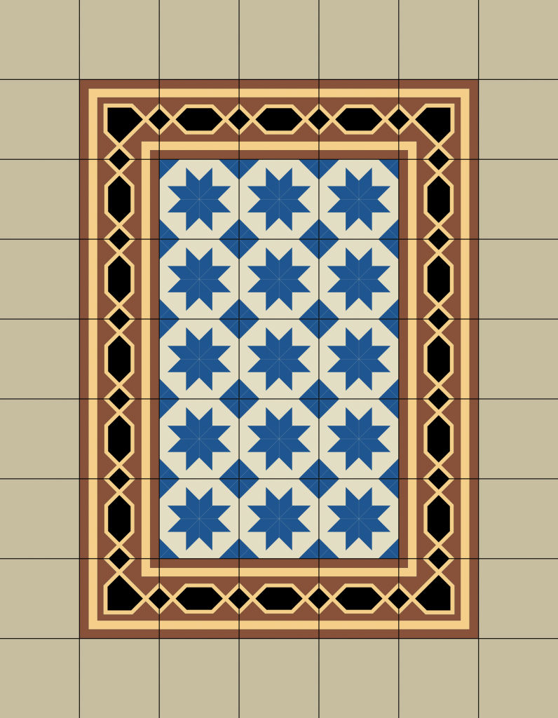
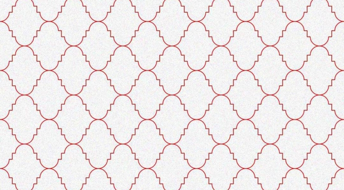
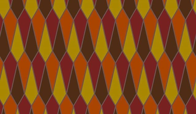
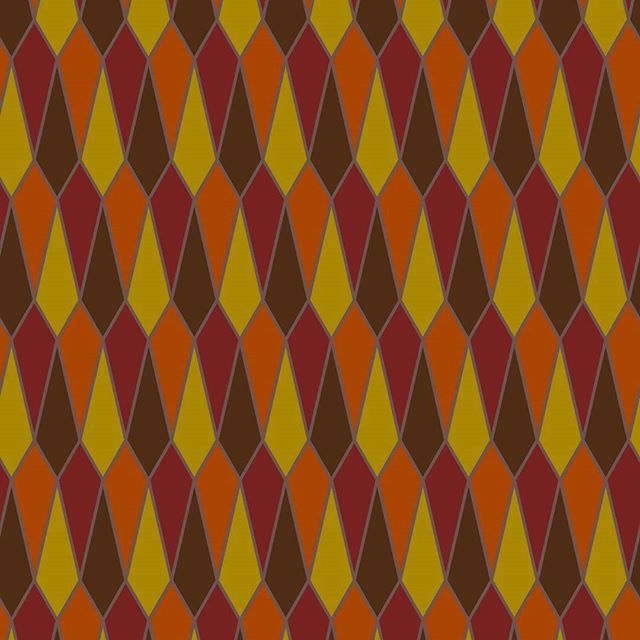
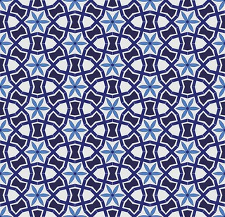
recreated from the Threlkeld Granite Co Ltd’s Album: Ornamental Granitic Tiles (1898), sheet 8
The Internet Archive has Threlkeld Granite Co Ltd’s Album of ornamental granitic tiles online, and I’m really digging the patterns of the hydraulic tiles they made. I’ve recreated some of their patterns in InkScape, and made this small demo by tiling bitmapped renderings.
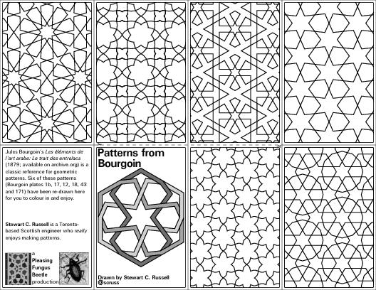
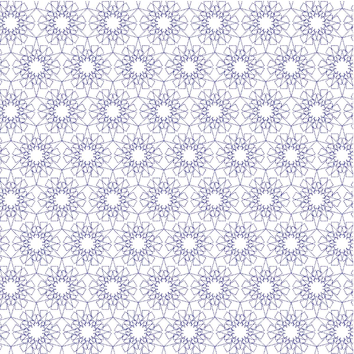
I made this two-colour plotted card for the MeFi “holiday card exchange – v.e.†thing. Pen plotter is a Roland DG DXY-1300 (1990s) using Roland 0.3 mm fibre-tip pens. Plot size is 123 × 91 mm, and is driven entirely from Inkscape 0.92.
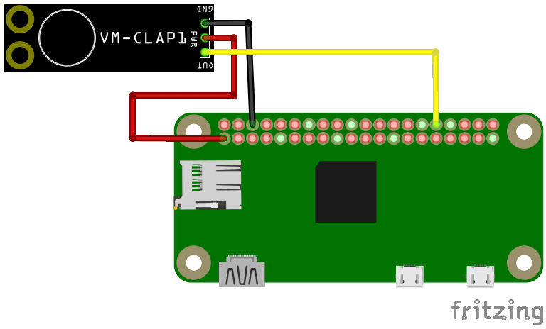
It should work in Breadboard and Schematic mode, but absolutely doesn’t work in PCB mode. This shouldn’t be a problem, as it’s only available as a standalone board. Fritzing doesn’t have any way to create new parts from scratch any more, so I had to base it on a somewhat similar-looking board, the SparkFun Electret Microphone Breakout.
I’m looking forward to see what I can do with gpiozero and the clap sensor.
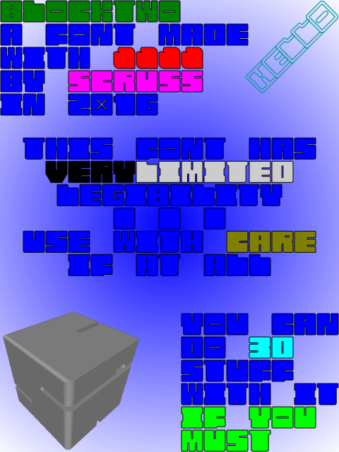
BlockTwo is a spectacularly ugly font mostly for playing about with 3D intersections in OpenSCAD. Not recommended for any but the most extreme display usage. Coverage is only A-Z caps, 0-9, heart and block.
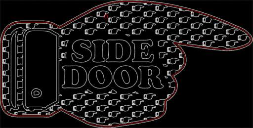
As Side Door sign v3 seemed to have fallen off, I needed to make a new one. With access to a laser cutter, I can make really permanent things now, so I designed this:
Yes, that’s a pointy thing filled with pointy things (all without thumbs, you’ll notice) and labelled with Cooper Black. Irony, much? Fe!
In order to get the sign to hang correctly, I needed to work out the centroid of the pointy outline. thedatachef/inkscape-centroid: Centroids for Inkscape paths and shapes to the rescue! Well, kinda. First off, the installer had a bug that said a Ruby file was a dependency when the plugin was in Python. So I forked the repo, made the change, tested it, and issued a pull request. So yay, working centroid calculations in Inkscape!
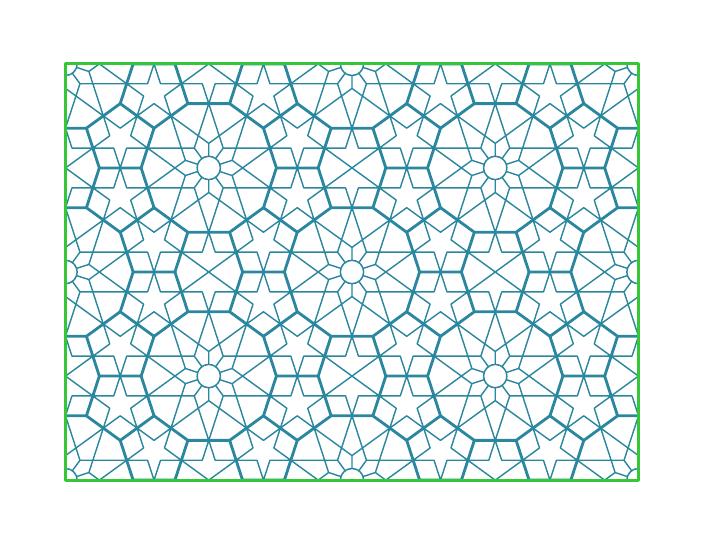
Secondly, the plugin only works well for simple shapes, like these:
But compound shapes? Not so well:
I guess it doesn’t like the negative moments generated by the holes, and does its own thing. Oh well.
A couple of months back at the GTALUG Graphics session, someone asked if Inkscape – the 2D vector graphics workhorse that everyone seems to use – could be scripted. We pretty much said that it couldn’t. Recently, I found out that it does support a limited form of scripting, and wish to pass this on.
The key to it is understanding Inkscape’s command verbs. These can be listed using:
inkscape --verb-list
These verbs map to Inkscape commands, and often have names linked to the menu they live in (such as “FileQuit†doing what you’d expect).
I had a task I had to repeat on many files: convert all the stroked lines to filled paths. You’d need to do this if you are laser engraving a simple drawing, but there are other applications for this too. Here’s a command that would do this for all objects in a drawing, and overwrite the input file:
Selects everything, and ungroups all objects (×3, to break up most nested groups);
Selects everything, and converts all objects to paths (so text, circles, polygons, spirals become paths, the lowest-level SVG object);
Selects everything, and combines everything into one path;
Selects everything, and converts all strokes to filled paths (so a two node straight line 1 mm wide would become a four node filled rectangle 1 mm thick);
Overwrite the input file, close it, and quit.
The process has some disadvantages:
It opens a window everytime. You can’t execute verbs without the GUI opening.
You can’t have another copy of Inkscape open while you do this.
Realistically, you can’t really do anything at your computer until this is done, as it’s popping up windows and shifting focus like crazy. (ssh types can say “heh!†in a smug manner now)
You can’t set parameters to verbs.
It will overwrite the input file.
It clogs up your “File / Recent†menu with all of the files you scripted.
Update, September 2016: this font was officially squee‘d over by Josh “cortex” Millard on the Metafilter Podcast #120: Hard Out There For A Nerd. I had the great pleasure of meeting Josh at XOXO 2016, too.
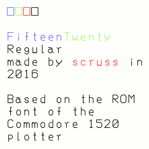
The Commodore 1520 was a tiny pen plotter sold for the Commodore 64 home computer. It looked like this:
I never owned one, but it seems it was more of a curiosity than a useful product.
From a nerdy point of view, however, this device was rather clever in that it packed a whole plotter command language, including a usable font, into 2048 bytes of ROM. Nothing is that small any more.
Based on my work with the Hershey font collection, I thought it would be fun to extract the coordinates and make a real OpenType font from these data. I’m sure others would sense the urgency in this task, too.
Since Commodore computers used a subset of ASCII, there’s a barely-usable set of characters in this first release. Notable missing characters include:
U+005C    \    REVERSE SOLIDUS
U+005E    ^    CIRCUMFLEX ACCENT
U+0060    `    GRAVE ACCENT
U+007B    {    LEFT CURLY BRACKET
U+007C    |    VERTICAL LINE
U+007D    }    RIGHT CURLY BRACKET
U+007E    ~    TILDE
I’ll get to those later, perhaps.
Huge thanks to all who helped get the data, and make the bits of software I used to make this outline font.
(Note: although the Project 64 Reloaded contains some extraction code to nominally produce an SVG font, it doesn’t work properly — and SVG fonts are pretty much dead anyway. I didn’t base any of my work on their Ruby code.)
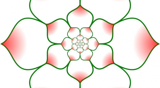
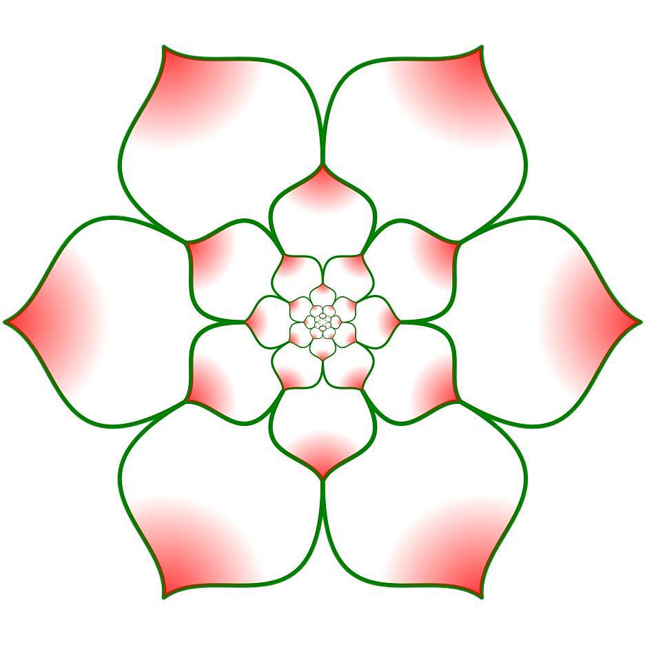
Original drawn in hand-coded PostScript from a path worked out using InkScape. Translating from InkScape’s SVG paths to PostScript is slightly annoying: PS uses Cartesian conventions, while SVG inverts the Y-axis. At least the SVG path commands map well to PostScript: m → moveto, c → curveto, Z → closepath, S → stroke.
There’s no magic to this figure. Each row of petals is half the length of the row outside it. As there are 6 petals arranged in a circle, each petal is 60° of arc. To make the half-step between rows, the petals are rotated 30°, so the rows have to be scaled by sin 30°, or ½.
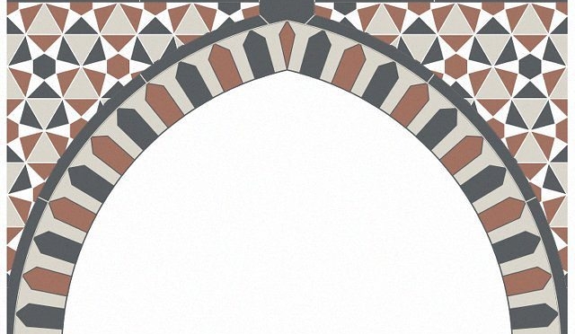
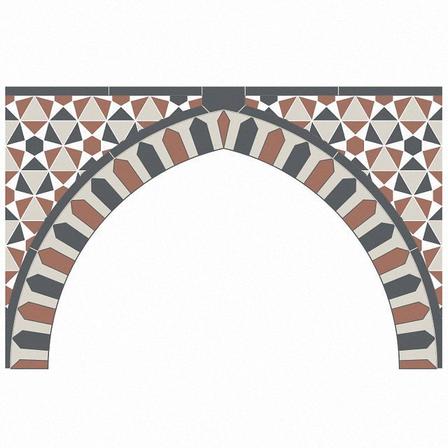
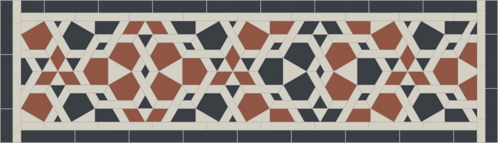
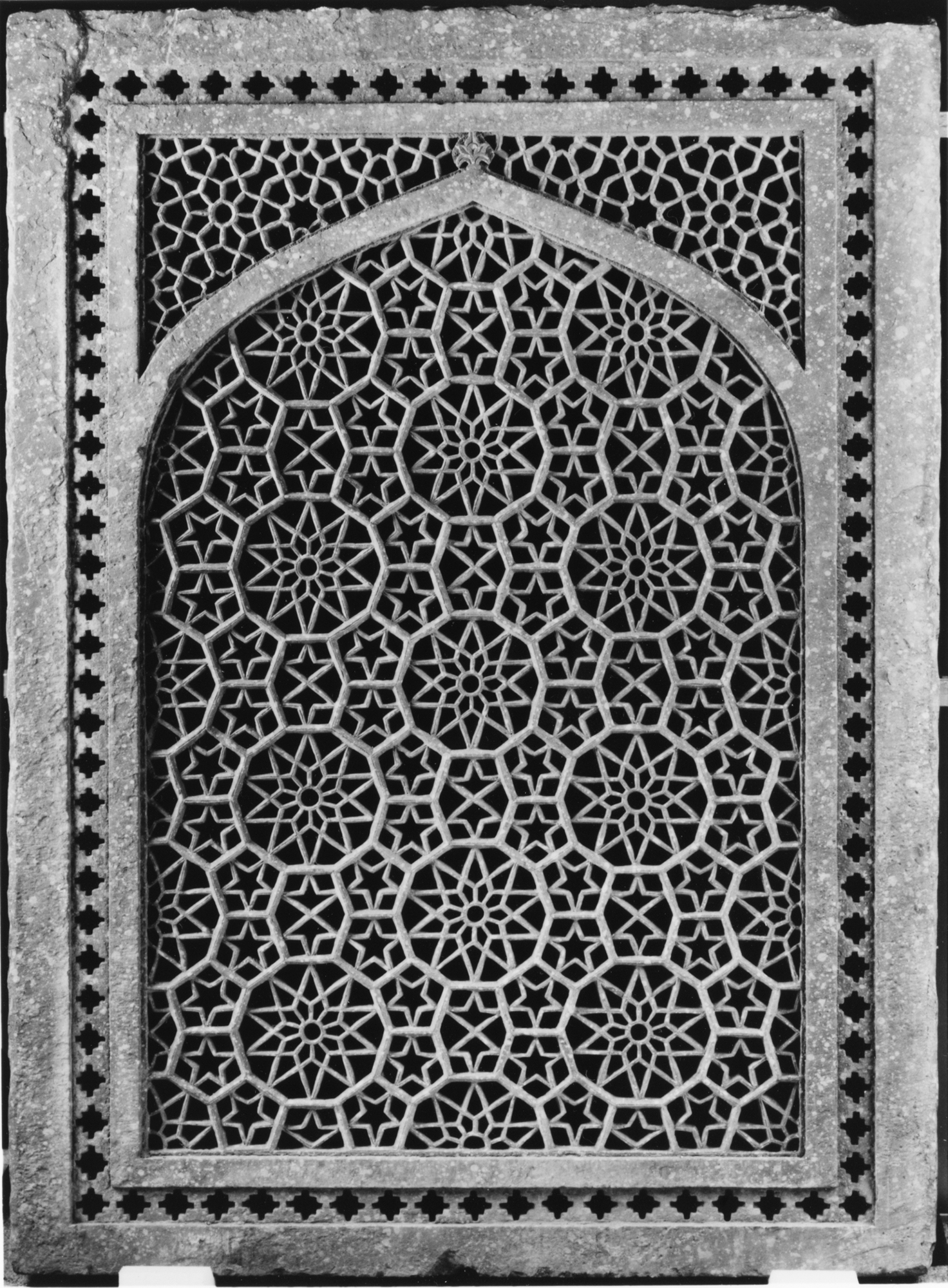
fell out of an arch design I was studying, and I thought it was too nice to throw away. Must’ve been something about the falling leaves that made me choose colours like these.
Drawing a circle between a centre point and one on the circumference is a common requirement in working up geometric patterns. If you need lines parallel to a radial line, or indeed any line at a fixed distance from another point, you need to draw a circle as a construction guide. the figure below will never be destined for design greatness, but it shows how they could be used:
(source SVG is linked from image, unfortunately)
The turquoise circles define the green parallel lines, and also the smaller green hexagon inside the black one. Drawing circles from a centre is what compasses do, yet Inkscape doesn’t have a tool to do it easily.
There is a way around this, though, that I picked up from this forum post. The poster’s method isn’t very clear, but in very brief summary, you need to construct a 3 point or 2 line-segment polyline with its nodes equidistant from the centre point, then use Render → Draw from Triangle … → Circumcircle to construct the circle. Simple? Um …
Okay, dodgy animation and point by point explanation coming up. With cusp, intersection and centre snapping all enabled:
badly drawn circumcircle animation for Inkscape
Draw two points: one for the centre, one on the circumference (I usually draw a short diagonal line as the pointand snap to the cusp node, as they are unobtrusive but easy to pick up the rotation centre.)
Click on the circumference point to select it
Click on the circumference point again to select the rotation centre and handles
Move the rotation centre of the point to the centre of your circle
Duplicate the point (Ctrl+D)
Rotate the point 90° (Object → Rotate 90° CW)
Duplicate the new point (Ctrl+D)
Rotate the new point 90° (Object → Rotate 90° CW) (You should now have three points arranged around a semicircle)
Draw two straight line segments through the three points
Select the line
Render → Draw from Triangle … → Circumcircle — and there’s your circle.
There’s probably another way to do this by creating a point (Ctrl+click in Line mode) giving it a line width, setting rounded line ends, then doing Path→Stroke to Path to get a buffer around the point, but I can’t work out how to do this reliably.
Oh, and the patten I made from the construction? Well, it might look okay on a paper towel …


.jpg#/media/File:Commodore_1520_printer_plotter_(adjusted).jpg)


