Speech from Python with the SYN6988 module

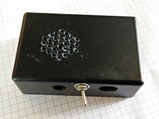
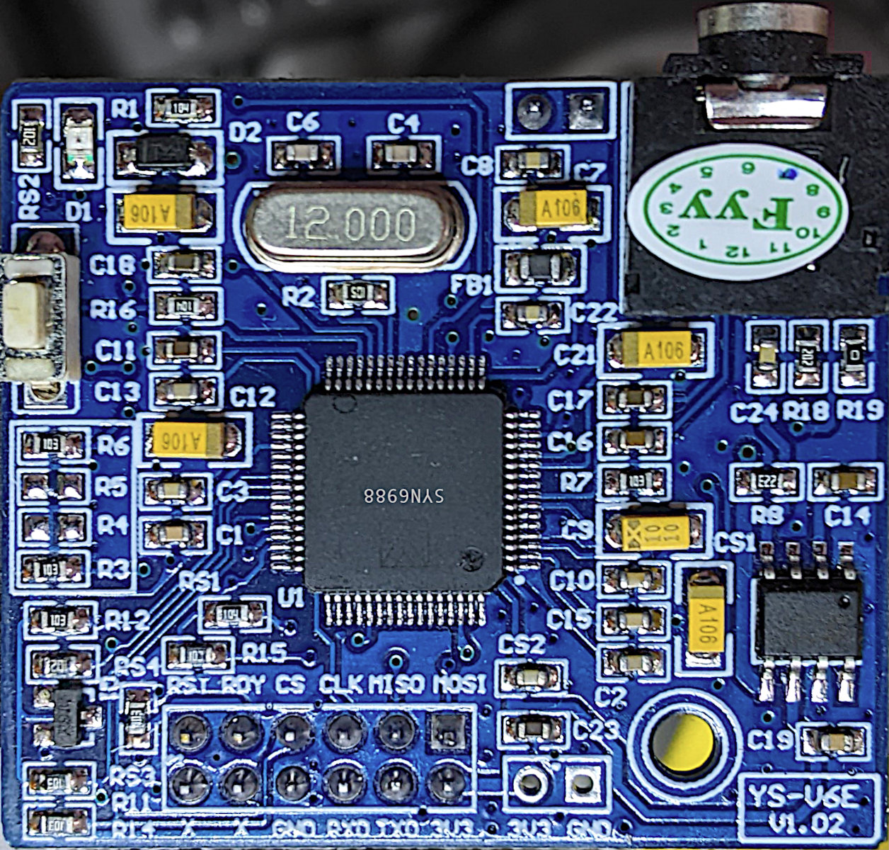
I’ve had one of these cheap(ish – $15) sound modules from AliExpress for a while. I hadn’t managed to get much out of it before, but I poked about at it a little more and found I was trying to drive the wrong chip. Aha! Makes all the difference.

So here’s a short narration from my favourite Richard Brautigan poem, read by the SYN6988.

Sensitive listener alert! There is a static click midway through. I edited out the clipped part, but it’s still a little jarring. It would always do this at the same point in playback, for some reason.

The only Pythonish code I could find for these chips was meant for the older SYN6288 and MicroPython (syn6288.py). I have no idea what I’m doing, but with some trivial modification, it makes sound.

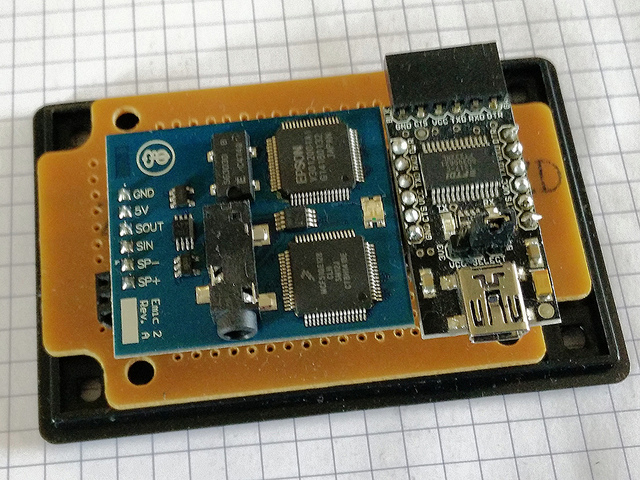
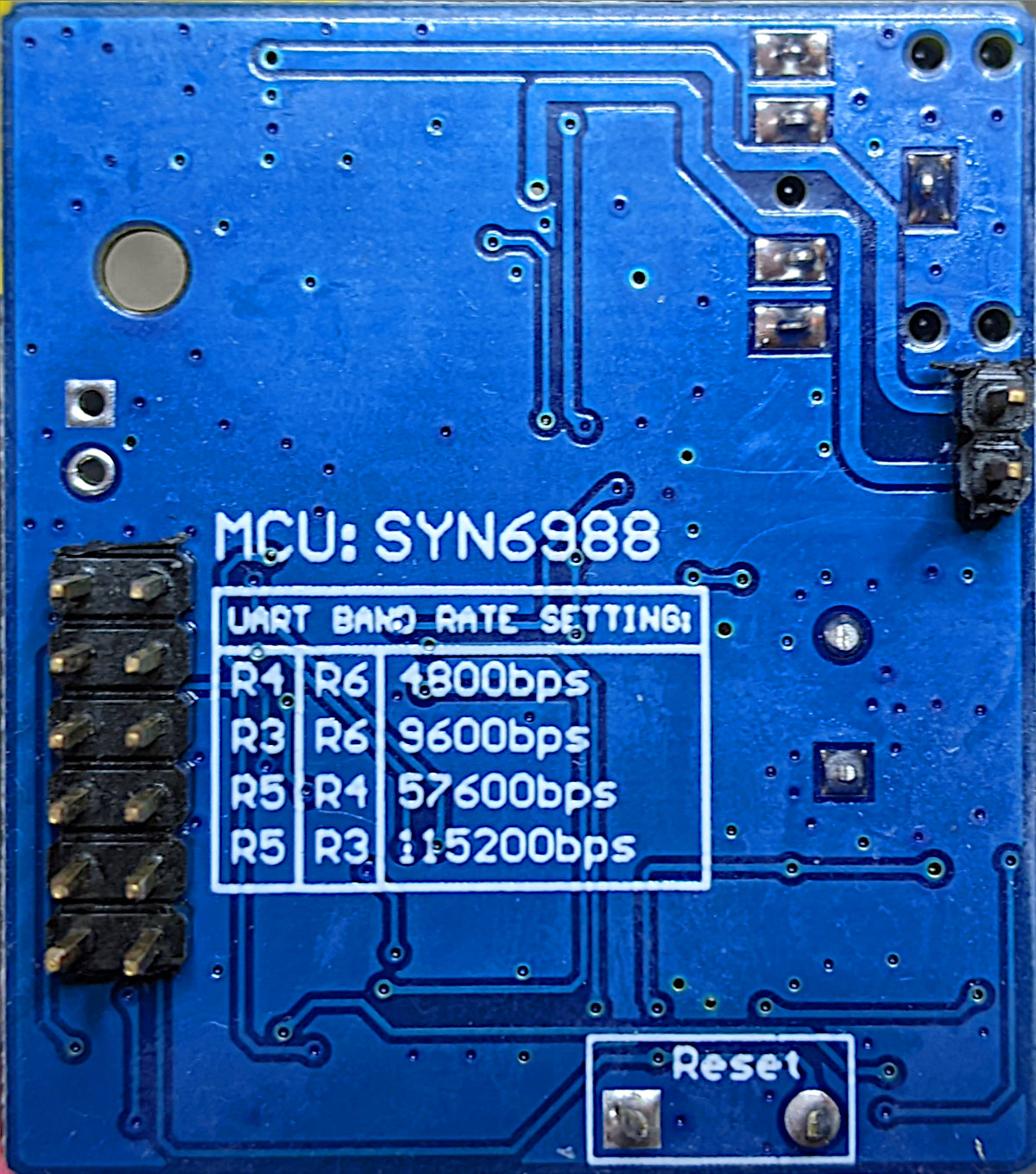
I used the simple serial UART connection: RX -> TX, TX -> RX, 3V3 to 3V3 and GND to GND. My board is hard-coded to run at 9600 baud. I used the USB serial adapter that came with the board.

Here’s the code that read that text:

#!/usr/bin/env python3
# -*- coding: utf-8 -*-

import serial
import time

# NB via MicroPython and old too! Also for a SYN6288, which I don't have
# nabbed from https://github.com/TPYBoard/TPYBoard_lib/

def sendspeak(port, data):
    eec = 0
    buf = [0xFD, 0x00, 0, 0x01, 0x01]
    buf[2] = len(data) + 3
    buf += list(bytearray(data, encoding='utf-8'))
    for i in range(len(buf)):
        eec ^= int(buf[i])
    buf.append(eec)
    port.write(bytearray(buf))

ser = serial.Serial("/dev/ttyUSB1", 9600)
sendspeak(ser, "[t5]I like to think [p100](it [t7]has[t5] to be!)[p100] of a cybernetic ecology [p100]where we are free of our labors and joined back to nature, [p100]returned to our mammal brothers and sisters, [p100]and all watched over by machines of loving grace")
time.sleep(8)
ser.close()

This code is bad. All I did was prod stuff until it stopped not working. Since all I have to work from includes a datasheet in Chinese (from here: ??????-SYN6988???TTS????) there’s lots of stuff I could do better. I used the tone and pause tags to give the reading a little more life, but it’s still a bit flat. For $15, though, a board that makes a fair stab at reading English is not bad at all. We can’t all afford vintage DECtalk hardware.

The one thing I didn’t do is used the SYN6988’s Busy/Ready line to see if it was still busy reading. That means I could send it text as soon as it was ready, rather than pausing for 8 seconds after the speech. This refinement will come later, most likely when I port this to MicroPython.

More resources:

[tɒk bɒks] — a tiny hardware speech synthesizer/TTS

[tÉ’k bÉ’ks]: case
[tÉ’k bÉ’ks]: case
[tÉ’k bÉ’ks]: inside
[tÉ’k bÉ’ks]: inside. The observant amongst you will notice that the speech board is 1/10″ further in than it should be for ideal alignment with the USB serial adapter.
Back in the 1980s, the now-defunct Digital Equipment Corporation (“DEC”) sold a hardware speech synthesizer based on Dennis Klatt’s research at MIT.  These DECTalk boxes were compact and robust, and — despite not having the greatest speech quality — gave valuable speech, telephone and reading accessibility to many people. Stephen Hawking’s distinctive voice is from a pre-DEC version of the MIT hardware.

DEC is long gone, and the licensing of DECTalk has wandered off into mostly software. Much to the annoyance of those in earshot, I’ve always enjoyed dabbling in speech synthesis. DECTalk hardware remains expensive, partly because of demand from electronic music producers (its vocoder-like burr is on countless tracks), but also because there are still many people who rely on it for daily life. I couldn’t justify buying a real DECTalk, but I found this: the Parallax Emic 2 Text-to-Speech Module.  For about $80, this stamp-sized board brings a hardware DECTalk implementation to embedded projects.

The Emic 2 is really marketed to microcontroller hobbyists: Make Your Arduino Speak! sorta thing. But I wanted to make a DECTalk-ish hardware box, with serial input, a speaker, and switchable headphone/line jack.  [tɒk bɒks] (a fair approximation of how I pronounce “Talk Box”) is the result.

Hardware

  • Parallax Emic 2 Text-to-Speech Module
  • OSEPP FTDI USB-Serial Breakout — there are many USB-Serial boards that would do this, but two points in this one’s favour are: i) it has header pins for breadboard use, and ii) I had a spare one.
  • Small 8Ω speaker element — the one I used is most likely a headphone element, bought from Active Surplus (RIP). This should be as small as you can get away with (and still hear) as the USB-Serial connection isn’t designed to supply audio power.
  • Header pins and sockets
  • Toggle switch
  • Small project box with perfboard
  • Jumper wires and solder

Connections

Emic 2             Serial
======             ======
 GND                GND
 5V                 Vcc
 SOUT               RXD
 SIN                TXD

Emic 2             Speaker
======             =======
 SP-                -
 SP+  (via switch)  +

Using it

You’ll need some kind of serial terminal connection. In a pinch, you can use the serial monitor that is in the Arduino development environment. Either way, identify your serial port (/dev/ttyUSBN, COMN:, or /dev/tty-usbserialNNNN) and find a way to send 9600 baud, 8N1 characters to it. Hit Return, and you should be greeted by the Emic 2’s : prompt (or a ?, followed by :). Whether you get the prompt or not depends on whether local echo is set or not. Either way, try sending this line:

SAll watched over by machines of loving grace.

You should hear a voice say the title of Richard Brautigan’s lovely poem All Watched Over by Machines of Loving Grace (caution: video link contains nekkid hippies). You should get the : prompt back once the the speech has stopped. And that’s all there is to it: send an S, followed by up to 1023 bytes of (basically ASCII) text, followed by a newline, and it will be spoken. There’s more detail, of course, in the Emic 2 documentation and the Emic 2 Epson/Fonix DECTalk 501 User’s Guide for changing voices, etc. Yes, you can make it sing. No, you probably shouldn’t, though.

Notes

  1. The Emic 2 has no serial flow control, so you have to wait until the module stops speaking (or you send it the stop command) before you can send more. The easiest way is to poll the serial port and see if there’s the : prompt waiting. Until you see the prompt, any text you send it may be lost.
  2. The Emic 2 is an embedded device; Unicode is a bit of a stretch. It’s supposed to accept ISO Latin-1 8-bit characters (handy for Spanish mode), though.
  3. Starting every speech line with S may make this board incompatible with assistive technology software such as the JAWS screen reader. I don’t think that this was the goal for Emic 2’s designers (Grand Idea Studio), however.
  4. The output from the audio jack has a fair bit of noise on it, and you need to set the volume quite low to avoid hiss and hum. Your experience may be different, as I may have accidentally made a ground loop. There is a faintly  audible click at the start and end of the text, too.
  5. The Emic 2 uses DECTalk v5 commands and phonemes. Many DECTalk resources on the web (like these songs) use v4 or older, which are subtly incompatible. I haven’t found a reliable conversion protocol yet.

To end, here’s the Emic 2’s “Dennis” voice reading all of Brautigan’s All Watched Over By Machines of Loving Grace:


(plain link: molg-dennis-140wpm-16khz.mp3)

(even plainer link if you can’t decode MP2 files: molg-dennis-140wpm.mp3)

(recorded and edited for length with Audacity. No hippies — nekkid, or otherwise — were harmed in the making of this recording.)

Thermal Printer driver for CUPS, Linux, and Raspberry Pi: zj-58


Update:build instructions have changed, 2019. If any manufacturer wants to see if their printer works, send me one (I’m easy to find) for free and I’ll check it out and add it here.

This might be my last post on mini-printers, as I’ve found a driver that just works with CUPS on Raspberry Pi. It also works on Ubuntu on my laptop, and should work (though untried) on Mac OS. You’ll have to build it from source, but it’s not too hard.

The hard part is working out if your thermal printer will work or not. There are many out there, and they’re all slightly different. If they support the ESC/POS bitmap command GS v 0 on 58 mm wide paper, they should work. The ones I’ve tested are:

  1. Catex POS5890U — USB, cheap, fast.
  2. “701” control board panel printer — fairly generic, decent quality printer with serial input. A bit slow for daily use at 9600 baud.
  3. Xiamen Embedded Printer DP-EH600 — as above.

The following should also work, but haven’t been tried:

  • Adafruit Mini Thermal Receipt Printer — again, serial, so not super fast.
  • Sparkfun thermal printer — which now appears to be identical to the Adafruit unit, and is referred to as the “A1 (or A2) micro panel printer” in the documentation.

Known not to work:

  • BTHT-V6 printer — which uses a completely different command set. (Roughly that of an Epson FX-80 for image commands, if you care.)

If you have a manual for your printer, check it to see if it prints bitmaps by sending a three byte header of 29 118 48 (or 1D 76 30 in hexadecimal). If you’re not sure, try it with a small test image, and be ready by the power switch …

Getting and building the driver

The driver is meant for a ZiJiang ZJ-58 printer, and lives here on Github: klirichek/zj-58.

Now read and follow the Building & Installing section of the README, and do what it says. I’ll wait …

Setting up the printer

This bit is much more graphical. You’ll need the system-config-printer package:

sudo apt install -y system-config-printer cups

Open up the printer settings window (Preferences → Print Settings):

2015-07-11-220946_452x281_scrotSelect the Add icon, and the New Printer window opens:

2015-07-11-221141_602x592_scrotThe POS5890U shows up as “Unknown” on my USB port, as Linux doesn’t know the name of this device from its USB ID.

Update (for the slightly desperate): In the land of “Things have changed!”, my Catex printer isn’t/wasn’t showing up at all. I had to resort to this in the Enter URI option:

thermal printer usb lp uri
(hey, this image doesn’t quite match the flow. Look only at the the “Device URI” bit please)

parallel:/dev/usb/lp0 seems to work. Another option might be looking at the output of

sudo /usr/lib/cups/backend/usb

which suggests that usb://Unknown/Printer might work too. (All of this might need to have been preceded by

sudo usermod -a -G lp pi

and a logout or reboot; I did say this was for the slightly desperate …)

If the above doesn’t apply, your printer might have an known ID, or show up as a serial port. Select the right one, and click Forward:

2015-07-11-221221_602x592_scrotHere, I’m really pleased that the driver is for a Zijiang unit, as it’s conveniently at the end of the list. Click Forward …

2015-07-11-221240_602x592_scrotNo options here, so again, Forward …

2015-07-11-221311_602x592_scrotI changed the name from the default ZJ-58 to the more unixly zj58. You don’t have to, but either way, Apply the changes.

2015-07-11-222030_452x281_scrotAnd there it is, registered as a printer!

Printer Options

Most printers expect paper wider than 58 mm, but mini-printers can’t do that. To tell the system about paper sizes, right click on the printer’s icon, and change the printer settings:

2015-07-11-222225_570x560_scrotA test page might print properly now, but you should probably go into Printer Options first:

2015-07-11-222239_570x560_scrotYou do want to set the media size to at least 58 × 210 mm. This is just the longest strip it will print in one ‘page’; if your print is shorter, it won’t waste extra paper. You can choose longer prints, but not wider. The default assume your local standard paper size which —be it A4, Letter, or whatever — will not be what you want here. Hit OK.

Printing something

You could print the self test page, but it’s long and boring. If you’re fairly sure your printer will be supported, try this scaled PDF version of the Raspberry Pi Logo: raspberry-pi-logo.  Printed and scanned, it came out like this:

raspberry-pi-logo-miniprinterNot the best rendition, but not bad for a $30 receipt printer. My test image came out like this (iffy scan, sorry):

zj58-driver-testI haven’t covered the intricacies of setting up serial port connections here; maybe another time. Also, there’s a short delay (maybe 10–20 s) between selecting Print and the printer coming to life. CUPS is pretty complex, and is doing things in the background while you wait.

(Seeing as I use their logo prominently up there, I should totes acknowledge that “Raspberry Pi is a trademark of the Raspberry Pi Foundation”. Also, I couldn’t have done all this without the support of Reed Zhao. Though Reed has moved on to bigger things and doesn’t sell printers any more, his help — not to mention the generous gift of a couple of printers — was very welcome.)

→ you might also be interested in my notes on mini-printers and Linux – it has some manuals too.

Notes on mini-printers and Linux

miniprinter galleryOver the last few weeks, I’ve been playing with a few small thermal printers. Meant as POS or information booth printers, they make a diverting project for the lo-fi printing enthusiast. While they all have common features — 58 mm/2¼” paper width, 8 pixel/mm resolution, 48 mm print width, serial connection — they all have their quirks. You may have seen these sold as the Adafruit Mini Thermal Receipt Printer or Sparkfun’s Thermal Printer, but there are many others. I’m going to write more on interfacing these directly to Raspberry Pi, Arduino, and (if I can navigate the documentation) a CUPS driver.

Update, July 2015: Here’s a CUPS driver: klirichek/zj-58, and my writeup on installing it on a Raspberry Pi — Thermal Printer driver for CUPS, Linux, and Raspberry Pi: zj-58

For now, I’m just leaving you a list of things I’ve found helpful for the DP-EH600 and 701 printers. Note that the similar-looking BTHT-v6 printer uses a completely different command set.

  • Replacement paper is sold as 2¼” × 30′. Staples have a box of 30 rolls for under $25 (item 279096, not on their website). Longer rolls don’t fit.
  • You’ll need a USB→TTL Serial adaptor, preferably one with DTR control. I use one from JY-MCU. In a pinch, you can use a simpler  Debug / Console Cable for Raspberry Pi, but you risk serial overruns and dodgy results. Remember that RX on the adaptor goes to TX on the printer, and vice versa.
  • A good solid power supply is needed; these printers draw ~8 W when printing. Some printers only support 5 V (for which a 3 amp adaptor would be ideal), others 5-9 V. The higher voltage makes text printing faster. You can’t drive these directly from your Raspberry Pi/Arduino power supply.
  • Linux serial ports are set to some defaults which may have been historically useful, but now corrupt 8-bit data. A trick I picked up here is to first issue the command
    stty -F /dev/ttyUSB1 0:0:0:0:0:0:0:0:0:0:0:0:0:0:0:0:0:0:0:0:0:0:0:0:0:0:0:0:0:0:0:0:0:0:0:0
    which clears all settings, then set the device up as you need it:
    stty -F /dev/ttyUSB1 speed 9600 raw cs8
    (Most of these printers default to 9600 baud. Your device may be called something different to ttyUSB1.)
  • I’ve written a couple of Python driver stubs which take an image and produce the relevant binary output:
    • scruss / esc-pos-image.py – prints an image as a single command. May not work on the SparkFun printer. Does not work on the BTHT-v6.
    • scruss / esc-pos-image-star.py – prints the image in 24 pixel deep bands. Can sometimes cause visible gaps in the printout, but will work on almost all printers, except the BTHT-v6.
  • These Python libraries also work, as long as you address the printer properly (right device, right speed):

Notes/Credits

  1. Reed Zhao (of Tangram Software) lent me a couple of different printers for testing after I bought a different one from him. He’s put a lot of work into sourcing these printers direct from the manufacturers. Thanks, Reed!
    NB: Reed doesn’t sell printers any more. Try eBay.
  2. Image credits for print samples:

Manuals/Docs

Posted more for historical reference:

Processing 2.1 + Oracle Java + Raspberry Pi + Serial + Arduino = ☺

Hey! This is very old and there’s an officially supported version out now coming out very soon.

Update for Raspberry Pi 2/Processing 2.2.1/Processing 3.0.5: Raspbian now ships with Java 8, and Processing only likes Java 7. oracle-java7-jdk is still in the repos, so install that, and follow the instructions below. It’s a bit flakey, but when it runs, runs quite fast on the Raspberry Pi 2. You might have more luck running Processing.js or p5.js in the browser.

With Sun Oracle hardfloat Java now available, Processing now runs at a decent clip on the Raspberry Pi. My old instructions are now very obsolete. Here are current, tested instructions for installing it under Raspbian.

[This is a particular solution to installing a Serial/Firmata-enabled Processing 2.1 distribution on a Raspberry Pi. Processing still has issues with other aspects of visual programming (particularly video) that I’m not addressing here.]

A lot of software is installed here, and much of it depends on previous steps. Don’t jump in mid-way and expect it to work.

Update the system

Always a good plan if you’re doing major upgrades:

sudo apt-get update
sudo apt-get dist-upgrade

Install Sun Oracle Java

sudo apt-get install oracle-java7-jdk

Check if the right version is installed as default: java -version should give

java version "1.7.0_40"
Java(TM) SE Runtime Environment (build 1.7.0_40-b43)
Java HotSpot(TM) Client VM (build 24.0-b56, mixed mode)

If you get anything else, you need to make Sun Oracle’s version the default:

sudo update-alternatives --config java

Download & Install Processing

Go to Download \ Processing.org and get the Linux 32-bit version.  It’s big; about 100 MB. I’m going to install it in my home directory, so the base path will be ~/processing-2.1. Extract it:

tar xvzf processing-2.1-linux32.tgz

Now you have to remove the included x86 Java runtime, and replace it with the Raspberry Pi’s armhf one:

rm -rf ~/processing-2.1/java 
ln -s /usr/lib/jvm/jdk-7-oracle-armhf ~/processing-2.1/java

You should now have a Processing installation that will run, but there’s some more we need to get serial and Arduino support.

Install the  java Simple Serial connector

Download jSSC-2.6.0-Release.zip and extract it:

unzip jSSC-2.6.0-Release.zip

Now overwrite the jssc.jar that ships with Processing with the one you just downloaded:

mv jSSC-2.6.0-Release/jssc.jar ~/processing-2.1/modes/java/libraries/serial/library/

(You can remove the jSSC folder now: rm -r jSSC-2.6.0-Release)

Test Processing’s serial support

You’re almost there! Fire up Processing:

~/processing-2.1/processing

and try Perhaps the World’s Most Boring Processing Sketchâ„¢:

// Example by Tom Igoe

import processing.serial.*;

// The serial port
Serial myPort;

// List all the available serial ports
println(Serial.list());

Screenshot from 2014-01-07 20:08:32When this runs (it’s a little slow), you should get a single line of output, which should start /dev/tty___:

/dev/ttyACM0

(I have an Arduino Leonardo attached, which usually appears as an ACM device.)

Installing Arduino/Firmata support

(I’m not going to go into uploading Firmata onto your Arduino here. All I can recommend is that you use the newest version at firmata/arduino, rather than the old code bundled with your Arduino distribution.)

Exit Processing, and download processing-arduino.zip from firmata/processing. Extract it into your Processing sketchbook:

unzip processing-arduino.zip -d ~/sketchbook/libraries/

For tedious reasons, you also have to rename one of the files:

mv  ~/sketchbook/libraries/arduino/library/Arduino.jar  ~/sketchbook/libraries/arduino/library/arduino.jar

Start up Processing again, and  save Most Probably the World’s Second Least Interesting Processing Programâ„¢:

import processing.serial.*;
import cc.arduino.*;
Arduino arduino;
int ledPin = 13;

void setup()
{
  println(Arduino.list());
  arduino = new Arduino(this, Arduino.list()[0], 57600);
  arduino.pinMode(ledPin, Arduino.OUTPUT);
}

void draw()
{
  arduino.digitalWrite(ledPin, Arduino.HIGH);
  delay(1000);
  arduino.digitalWrite(ledPin, Arduino.LOW);
  delay(1000);
}

Screenshot from 2014-01-07 21:13:54
What this sketch does is emulate the µC’s “Hello World” program, Blink. It flashes the board’s LED once per second. Boring? Yes. But if it worked, you have a working Processing 2.1 installation on your Raspberry Pi. Go forth and make more interesting things.
(Props to bitcraftlab/wolfing for the basic outline for installing Processing, and for samaygoenka for the prodding needed to update and test the Processing installation process. If you’re still stuck, the Processing 2.0 Forum and the Raspberry Pi Forum are good places to ask.)

Adding a Bluetooth serial terminal to Raspberry Pi

Hey! This article is really old. The advice given here will not work on a Raspberry Pi 3, and will need some care with recent versions of Raspbian.

Sometimes you find a computer component that’s so cheap, that works so well, that you’re amazed you managed to live without it for so long. The JY-MCU Arduino Bluetooth Wireless Serial Port Module is that component for me right now.

JY-MCU Arduino Bluetooth Wireless Serial Port Module from dx.com

This little board is a cheap ($8.50!) Bluetooth serial port. It’s happy with the Raspberry Pi’s 3.3 V logic levels, and will communicate at standard rates between 1200 and 1,382,400 baud. It even comes with a nifty little cable which is just the right polarity for the Raspberry Pi’s GPIO pins. It’s really meant to do serial comms on an Arduino, but it’s not limited to that.

What this board allows you to do is connect to your Raspberry Pi’s serial console via Bluetooth. That way, you can have your Raspberry Pi hidden away somewhere, and yet still log in as if you were talking to it directly through a serial cable. Combine this with a USB wireless adaptor (like the Belkin N150 that I use) and you’ve got a wireless device you can always connect to, even if your network goes down.

In order to use this device with your Raspberry Pi, you’re going to have to do some reconfiguration. Exactly what reconfiguration you do depends on some additional hardware:

  1. If you have a USB-TTL Serial converter (like an FTDI Friend, FTDI Basic Breakout – 3.3V, or the one I use, the OSEPP FTDI), you can reconfigure the Bluetooth module to run at 115,200 baud, the default speed of the Raspberry Pi’s serial port.
  2. If you don’t have the serial converter, you’ll need to reconfigure the Raspberry Pi’s serial terminal to run at the JY-MCU Bluetooth adapter’s default 9600 baud.

To reconfigure the Bluetooth module to run at 115,200 baud

(I chose this option, as it allows me to use the Bluetooth module with Firmata on an Arduino, too.)

The JY-MCU board comes with no instructions, but all the reconfiguration commands you’ll need are explained here: hc06_linvor_1.5_at_command_set [[hc06_linvor_1.5_at_command_set]] (cached copy; original has gone) While you’re setting the communications speed, you’ll probably also want to change the device name (so you can more easily recognize your own board, as the default is something like “Linvor”) and PIN (for that warm feeling of security that only a four digit code can provide). The device is configured using AT commands (or as we eldsters call them, Hayes commands) by plugging it directly into a USB-TTL Serial device attached to your computer. Here’s how you wire it:

USB-TTL Serial    Bluetooth Serial
================= =================
GND               GND
VCC               VCC
TXD               RXD
RXD               TXD

Note that TXD and RXD are crossed. The Bluetooth unit runs on a 3.6-6V supply, but 3.3V logic. To enter the AT commands, start a serial terminal (Hyperterm, minicom, screen …) at 9600 baud talking to the USB-Serial adapter, and copy and paste these commands in:

AT+NAMEBluey
AT+PIN4321
AT+BAUD8

You’ll have to disconnect the terminal and reconnect at 115,200 baud, as that last command just reset the Bluetooth device’s speed. You might want to use other settings than Bluey for the name and 4321 for the PIN, too.

Update: check that your Raspberry Pi’s /boot/cmdline.txt contains:

console=ttyAMA0,115200

You will not get a login prompt otherwise.

Now go to Using the Device.

To reconfigure the Raspberry Pi’s serial terminal to run at 9600 baud

Serial terminals traditionally ran at 9600 baud, and that seems a bit slow these days. But, if you don’t have a way of setting up the Bluetooth device differently, 9600 is what you’re stuck with. You’ll need to edit your Raspberry Pi’s /boot/cmdline.txt so that the part that previously read:

console=ttyAMA0,115200 kgdboc=ttyAMA0,115200

to

console=ttyAMA0,9600 kgdboc=ttyAMA0,9600

Note that this file should only contain one line, so be careful you don’t add extra line breaks or your Raspberry Pi won’t boot. Save the file, reboot your Raspberry Pi, and go to the next section.

Using the Device

On your Raspberry Pi, connect the Bluetooth Wireless Serial Port Module as follows:

Raspberry Pi      Bluetooth Serial
================= =================
5V  (GPIO Pin  2) VCC
GND (GPIO Pin  6) GND
TXD (GPIO Pin  8) RXD
RXD (GPIO Pin 10) TXD

(Despite the minimum 3.6V rating, I’m happily running mine from the 3V3 power, GPIO Pin 1. YMMV.)

When the board gets power, but isn’t paired, the LEDs on the Bluetooth module flash quickly. Now you need to pair the device with your computer (use 0000 as the PIN, or whatever you chose if you changed it), and it will appear as a serial port on your machine. On my Mac, that’s a device called /dev/tty.Bluey-DevB. The LEDs stop flashing when the port goes into use. Open up a serial terminal, set the device and speed correctly, and if all goes well, you should see:

Debian GNU/Linux wheezy/sid raspberrypi ttyAMA0

raspberrypi login:

Success!

Controlling an Arduino from Raspberry Pi using Processing

Hey! This article is really old! The code might still work, but I’ve updated the installation instructions for Processing 2.1 and Sun Oracle Java here: Processing 2.1 + Oracle Java + Raspberry Pi + Serial + Arduino = ☺.

This might not look like much, but it was a lot of work to get here. It’s the display from a small Processing sketch, running on a Raspberry Pi, talking to an Arduino controlling the brightness of an LED with the slider, and reading from an LM35 temperature sensor.

I wanted to see if I could get graphical control of an Arduino on the Raspberry Pi. I wrote about the simplest sketch in Processing that combined output (to control a small green LED through a resistor) and input (from an LM35, that simplest of sensors). This is how it looks running on a slightly faster machine than the Raspberry Pi:

LED at half brightness, LM35 showing 25°C

LED off, sensor at 26°C

LED full on, LM35 warmed up

I had the same results on the Raspberry Pi; just much, much slower. The sketch is below the fold.

Running Processing on Raspberry Pi

Processing is both written in and generates Java, so there’s some hope that it can run on most platforms. Up-to-date installation instructions. These instructions are modified from Processing sur Raspberry Pi, for which thanks are given to the original author:

  1. Install the JDK and Java serial library: sudo apt-get install librxtx-java openjdk-6-jdk
  2. Download the Linux version of Processing, and unpack it to somewhere permanent in your home directory
  3. Delete the java folder in the Processing directory; for me, that was processing-1.5.1/java
  4. Replace that java folder with a link to your system’s installation: ln -s /usr/lib/jvm/java-6-openjdk-armhf java
  5. In the Processing folder, remove or rename modes/java/libraries/serial/library/linux32/librxtxSerial.so; it’s an x86 binary, and will fail
  6. In the Processing folder, also remove modes/java/libraries/serial/library/RXTXcomm.jar, and replace it with a copy of /usr/share/java/RXTXcomm.jar
    (If you don’t do this, you’ll get a warning: “WARNING:  RXTX Version mismatch”, and any serial comms will fail.)
  7. Download and install the controlP5 library for Processing
  8. Download and install the Arduino library for Processing
  9. Program your Arduino with Firmata; the version that comes with the Arduino software is fine a bit old.
  10. Connect your Arduino to the Raspberry Pi with a USB cable; it may require external power.

Now fire up Processing. It will used to take a while to start up, and will throw the following warning:

Despite this, it should eventually should start up fine:

Now, this is slow. It takes tens of seconds to start up. It might not be the most practical development tool, but Processing sketches are very portable, so you can develop on one machine, and then run on the Raspberry Pi.

The code at the end of this article expects:

  • an Arduino running the Firmata DAQ sketch attached to a USB port;
  • a small LED connected from digital pin 3, through a 1kΩ resistor to ground;
  • an LM35 with the following connections: +Vs → +5V, Vout → analogue pin 0, and GND → GND.

If you run this, after about half a minute, the blank sketch window appears, and about half a minute later, the slider and temperature reading appears. If it doesn’t, there’s a good chance that the serial libraries are wrong. Try this sketch:

import processing.serial.*;
import cc.arduino.*;

Arduino arduino;
println(Arduino.list());

This should return a number and a serial port where the Arduino was found; something like ‘[0] /dev/ttyACM0’.

What I really want to do now is get this same hardware running with Python and tkinter. It’s not that Python’s my favourite language; it’s just that the Raspberry Pi Foundation chose Python as the official language for the board. I’d rather work to further the aims of this educational foundation rather than work against it. Processing’s pretty much unworkably slow on the Raspberry Pi — but it does work!