Hey! This is very old and there’s an officially supported version out now coming out very soon.
Update for Raspberry Pi 2/Processing 2.2.1/Processing 3.0.5: Raspbian now ships with Java 8, and Processing only likes Java 7. oracle-java7-jdk is still in the repos, so install that, and follow the instructions below. It’s a bit flakey, but when it runs, runs quite fast on the Raspberry Pi 2. You might have more luck running Processing.js or p5.js in the browser.
With Sun Oracle hardfloat Java now available, Processing now runs at a decent clip on the Raspberry Pi. My old instructions are now very obsolete. Here are current, tested instructions for installing it under Raspbian.
[This is a particular solution to installing a Serial/Firmata-enabled Processing 2.1 distribution on a Raspberry Pi. Processing still has issues with other aspects of visual programming (particularly video) that I’m not addressing here.]
A lot of software is installed here, and much of it depends on previous steps. Don’t jump in mid-way and expect it to work.
Update the system
Always a good plan if you’re doing major upgrades:
sudo apt-get update
sudo apt-get dist-upgrade
Install Sun Oracle Java
sudo apt-get install oracle-java7-jdk
Check if the right version is installed as default: java -version should give
java version "1.7.0_40"
Java(TM) SE Runtime Environment (build 1.7.0_40-b43)
Java HotSpot(TM) Client VM (build 24.0-b56, mixed mode)
If you get anything else, you need to make Sun Oracle’s version the default:
sudo update-alternatives --config java
Download & Install Processing
Go to Download \ Processing.org and get the Linux 32-bit version. It’s big; about 100 MB. I’m going to install it in my home directory, so the base path will be ~/processing-2.1. Extract it:
tar xvzf processing-2.1-linux32.tgz
Now you have to remove the included x86 Java runtime, and replace it with the Raspberry Pi’s armhf one:
rm -rf ~/processing-2.1/java
ln -s /usr/lib/jvm/jdk-7-oracle-armhf ~/processing-2.1/java
You should now have a Processing installation that will run, but there’s some more we need to get serial and Arduino support.
Install the java Simple Serial connector
Download jSSC-2.6.0-Release.zip and extract it:
unzip jSSC-2.6.0-Release.zip
Now overwrite the jssc.jar that ships with Processing with the one you just downloaded:
mv jSSC-2.6.0-Release/jssc.jar ~/processing-2.1/modes/java/libraries/serial/library/
(You can remove the jSSC folder now: rm -r jSSC-2.6.0-Release)
Test Processing’s serial support
You’re almost there! Fire up Processing:
~/processing-2.1/processing
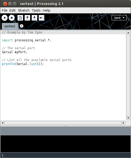
and try Perhaps the World’s Most Boring Processing Sketchâ„¢:
// Example by Tom Igoe

import processing.serial.*;

// The serial port
Serial myPort;

// List all the available serial ports
println(Serial.list());
 When this runs (it’s a little slow), you should get a single line of output, which should start /dev/tty___:
/dev/ttyACM0
(I have an Arduino Leonardo attached, which usually appears as an ACM device.)
Installing Arduino/Firmata support
(I’m not going to go into uploading Firmata onto your Arduino here. All I can recommend is that you use the newest version at firmata/arduino, rather than the old code bundled with your Arduino distribution.)
Exit Processing, and download processing-arduino.zip from firmata/processing. Extract it into your Processing sketchbook:
unzip processing-arduino.zip -d ~/sketchbook/libraries/
For tedious reasons, you also have to rename one of the files:
mv ~/sketchbook/libraries/arduino/library/Arduino.jar ~/sketchbook/libraries/arduino/library/arduino.jar
Start up Processing again, and save Most Probably the World’s Second Least Interesting Processing Programâ„¢:
import processing.serial.*;
import cc.arduino.*;
Arduino arduino;
int ledPin = 13;

void setup()
{
  println(Arduino.list());
  arduino = new Arduino(this, Arduino.list()[0], 57600);
  arduino.pinMode(ledPin, Arduino.OUTPUT);
}

void draw()
{
  arduino.digitalWrite(ledPin, Arduino.HIGH);
  delay(1000);
  arduino.digitalWrite(ledPin, Arduino.LOW);
  delay(1000);
}
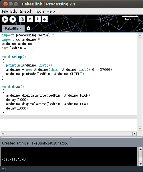
What this sketch does is emulate the µC’s “Hello World†program, Blink. It flashes the board’s LED once per second. Boring? Yes. But if it worked, you have a working Processing 2.1 installation on your Raspberry Pi. Go forth and make more interesting things.
(Props to bitcraftlab/wolfing for the basic outline for installing Processing, and for samaygoenka for the prodding needed to update and test the Processing installation process. If you’re still stuck, the Processing 2.0 Forum and the Raspberry Pi Forum are good places to ask.)


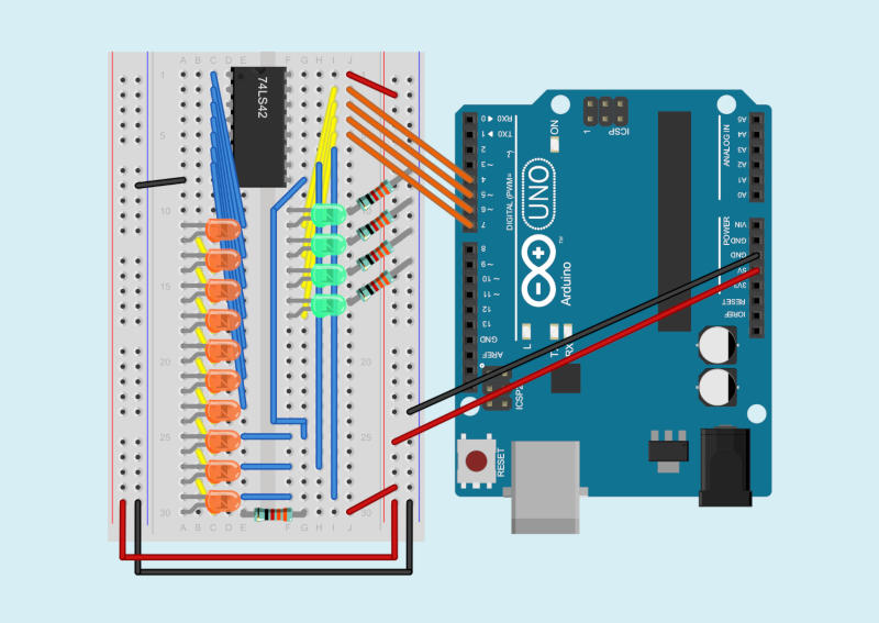


 Phil sent me a note last week asking how to turn an LED on or off using Python talking through Firmata to an Arduino. This was harder than it looked.