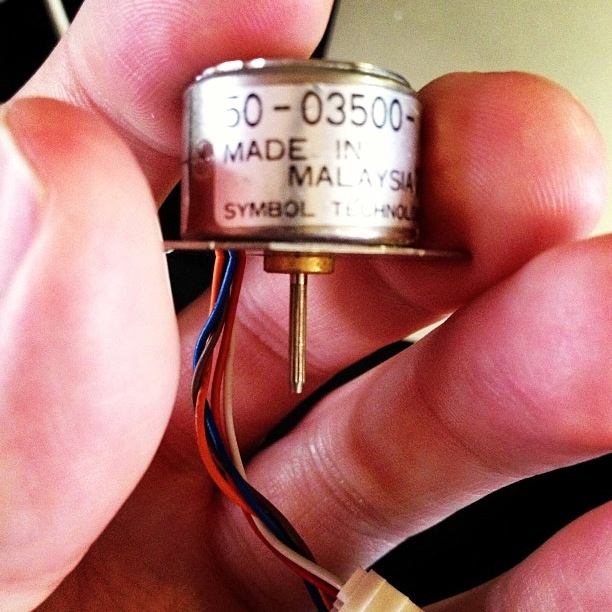
yay tiny stepper motor!

Active Surplus Electronics is the best. I was wanting to learn about driving stepper motors from a microcontroller, but didn’t want to spend a lot or rig up a complex power supply. Active Surplus had a bin of tiny 5V stepper motors at under $3 each. The one I bought is marked:

50-03500-    028
MADE IN
 MALAYSIA   7115
SYMBOL TECHNOLOGIES, INC.

I have no data sheet, but I’ve been able to work out that it’s a unipolar stepper motor, 20 steps/revolution (18°/step; quite coarse), wired:

  • Centre tap: Brown
  • Coil A: White, Red
  • Coil B: Orange, Blue

It’s small enough to be driven directly by USB power through an Arduino and the Adafruit Motor Shield. No idea how much torque this thing puts out, but it can’t be much.

(Setting up my motor shield was a pain, as I’d accidentally put non-stacking headers on it. This required an hour of swearing-filled desoldering; lead-free through-hole desoldering is just the worst*. With wick and solder pump, I finally managed to clear everything up well enough to fit the new headers.)

Servo Control from pyfirmata + arduino

Hey! This article is really old! So old, in fact, that I clearly thought that saying (ahem) “w00t w00t” was a good idea. Information here may be misleading and possibly wrong. You probably want to be using a newer client library and you definitely want to use an Arduino IDE ≥ 1.6 and not the ancient one that comes with Raspbian.

pyFirmata‘s documentation is, to be charitable, sparse. After writing Raspberry Pi, Python & Arduino *and* a GUI (which should be making an appearance in The MagPi soon, w00t w00t yeet!), I looked at pyFirmata again to see what it could do. That pretty much meant digging through the source.

Firmata can drive hobby servos, and if you’re not driving too many, you can run them straight from the Arduino with no additional power. I used a standard cheapo-but-decent Futaba S3003, which gives you about 180° of motion. The particular one I tried started to make little growly noises past 175°, so in the example below, that’s hardcoded as the limit.

#!/usr/bin/python
# -*- coding: utf-8 -*-
# move a servo from a Tk slider - scruss 2012-10-28

import pyfirmata
from Tkinter import *

# don't forget to change the serial port to suit
board = pyfirmata.Arduino('/dev/tty.usbmodem26271')

# start an iterator thread so
# serial buffer doesn't overflow
iter8 = pyfirmata.util.Iterator(board)
iter8.start()

# set up pin D9 as Servo Output
pin9 = board.get_pin('d:9:s')

def move_servo(a):
    pin9.write(a)

# set up GUI
root = Tk()

# draw a nice big slider for servo position
scale = Scale(root,
    command = move_servo,
    to = 175,
    orient = HORIZONTAL,
    length = 400,
    label = 'Angle')
scale.pack(anchor = CENTER)

# run Tk event loop
root.mainloop()

The code above makes a slider (oh, okay, a Tkinter Scale widget) that moves the servo connected to Arduino pin D9 through its whole range. To set the servo position, you just need to write the angle value to the pin.

I haven’t tried this with the Raspberry Pi yet. It wouldn’t surprise me if it needed external power to drive the Arduino and the servo. This might be a good excuse to use my Omega-328U board — it’s Arduino code compatible, runs from an external power supply, and has Signal-Voltage-Ground (SVG) connectors that the servo cable would just plug straight into.

LaunchPad MSP430 pomodoro timer using Energia

I know a lot of people who bought the Texas Instruments MSP430 LaunchPad development kit but never really got into it. I’m one of them; the $4.30 purchase price was compelling, but the requirement to install a huge proprietary IDE (with its own embedded C dialect) was just too much.

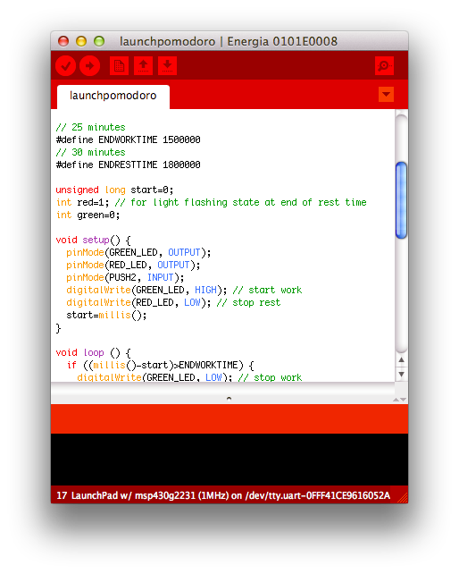
For this reason, Energia is great. It’s a fork of the Wiring/Arduino development environment for the MSP430. Looks just like Arduino, but quite red:

The basics of the language are the same, although the pin names and functions are different from the Arduino. The basic board also has a red and a green LED, a user button, and the obligatory reset button.

Just to try out Energia, I wanted a useful project that only used the onboard hardware. I came up with a version of a pomodoro timer, similar to the one used in The Pomodoro Technique® time management method. The one I made has the following features:

  • 25 minute “green light” work period
  • 5 minute “red light” rest period
  • At the end of the rest period, the green and red lights flash. You can choose to restart the timer (with the reset button), or turn the lights off with the user button.
  • You can turn the timer off at any time with the user button, and restart it from zero with the reset button.

For me, this electronic version has several advantages over the wind-up official timer:

  • it doesn’t tick or ring distractingly
  • it’s cheaper than the real thing
  • it always resets to the same time.

It does have a couple of possible disadvantages, though:

  • it doesn’t give an indication of time left
  • it’s not very accurate, since it uses the MSP430’s internal oscillator. Mine seems to give an approximately 26 minute work period, with a rest time that’s proportionally longer.

Here’s the code (tested on a MSP-EXP430G2 board, version 1.4):

/*

 launchpomodoro - simple task/rest timer for TMS430/Energia

 On reset: Green LED on for 25 minutes
 After 25 minutes: Red LED
 After 30 minutes: Flashing Red/Green LED (until reset)
 On button press: all lights off.

 scruss - 2012-10-15

 */

// 25 minutes
#define ENDWORKTIME 1500000
// 30 minutes
#define ENDRESTTIME 1800000

unsigned long start=0;
int red=1; // for light flashing state at end of rest time
int green=0;

void setup() {
  pinMode(GREEN_LED, OUTPUT);
  pinMode(RED_LED, OUTPUT);
  pinMode(PUSH2, INPUT);
  digitalWrite(GREEN_LED, HIGH); // start work
  digitalWrite(RED_LED, LOW); // stop rest
  start=millis();
}

void loop () {
  if ((millis()-start)>ENDWORKTIME) {
    digitalWrite(GREEN_LED, LOW); // stop work
    digitalWrite(RED_LED, HIGH); // start rest
  }

  if ((millis()-start)>ENDRESTTIME) {
    flicker(); // warn that we've overrun
  }

  if (digitalRead(PUSH2) == LOW) { // push quiet/off switch
    off();
  }
}

void flicker() { // toggle LEDs and wait a bit
  red=1-red;
  green=1-green;
  digitalWrite(GREEN_LED, green);
  digitalWrite(RED_LED, red);
  delay(333);
}

void off() { // appear to be off
  digitalWrite(GREEN_LED, LOW); // lights off
  digitalWrite(RED_LED, LOW);
  while (1) { // loop until reset
    delay(50);
  }
}

(or if you’d rather have the archived sketch: launchpomodoro-121015a.zip.)

It would be trivial to port this to Arduino, but you would need some external LEDs, resistors and a pushbutton.

Raspberry Pi, Python & Arduino *and* a GUI …

Whee! This entry was the basis of the cover article of The MagPi issue 7. Read it on Issuu, or download the PDF.

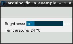
Okay, so maybe I can stop answering the StackExchange question “How to attach an Arduino?” now. While I got the Arduino working with pyFirmata on the Raspberry Pi before, it wasn’t that pretty. With a TkInter front end, it actually looks like some effort was involved. You can happily brighten and dim the LED attached to the Arduino all you want, while the temperature quietly updates on the screen independent of your LED frobbing.

I’d never used TkInter before. For tiny simple things like this, it’s not that hard. Every widget needs a callback; either a subroutine it calls every time it is activated, or a variable that the widget’s value is tied to. In this case, the Scale widget merely calls a function set_brightness() that sets a PWM value on the Arduino.

Updating the temperature was more difficult, though. After TkInter has set up its GUI, it runs in a loop, waiting for user events to trigger callback events. It doesn’t really allow you to run another loop alongside its main event loop. What you have to do then is set up a routine which is called periodically using TkInter’s after() function, which calls a subroutine after a set amount of time. If this subroutine ends with another call to after() to call itself again, it will maintain its own event loop separate from TkInter’s GUI loop. This is what I do in the get_temp() subroutine, which schedules itself after a ½ second.


#!/usr/bin/python
# -*- coding: utf-8 -*-

# graphical test of pyfirmata and Arduino; read from an LM35 on A0,
#                                          brighten an LED on D3 using PWM
# Connections:
# - small LED connected from D3, through a 1kΩ resistor to GND;
# - LM35: +Vs -> +5V, Vout -> A0, and GND -> GND.
# scruss, 2012-08-16 - tested on Raspberry Pi and Arduino Uno

import pyfirmata
import sys                              # just for script name and window
from Tkinter import *

# Create a new board, specifying serial port
board = pyfirmata.Arduino('/dev/ttyACM0')

# start an iterator thread so that serial buffer doesn't overflow
it = pyfirmata.util.Iterator(board)
it.start()

# set up pins
pin0=board.get_pin('a:0:i')             # A0 Input      (LM35)
pin3=board.get_pin('d:3:p')             # D3 PWM Output (LED)

# IMPORTANT! discard first reads until A0 gets something valid
while pin0.read() is None:
    pass

def get_temp():                         # LM35 reading in °C to label
    selection = "Temperature: %6.1f °C" % (pin0.read() * 5 * 100)
    label.config(text = selection)
    root.after(500, get_temp)           # reschedule after half second

def set_brightness(x):  # set LED; range 0 .. 100 called by Scale widget
    y=float(x)
    pin3.write(y / 100.0)               # pyfirmata expects 0 .. 1.0

def cleanup():                          # on exit
    print("Shutting down ...")
    pin3.write(0)                       # turn LED back off
    board.exit()

# now set up GUI
root = Tk()
root.wm_title(sys.argv[0])              # set window title to program name
root.wm_protocol("WM_DELETE_WINDOW", cleanup) # cleanup called on exit
scale = Scale( root, command=set_brightness, orient=HORIZONTAL, length=400,
               label='Brightness')      # a nice big slider for LED brightness
scale.pack(anchor=CENTER)

label = Label(root)
label.pack(anchor='nw')                 # place label up against scale widget

root.after(500, get_temp)               # start temperature read loop
root.mainloop()

The program takes a few seconds to start on the Raspberry Pi, mainly because initializing pyFirmata over a serial line and waiting for the duff values to subside takes time. I tried to exit the program gracefully in the cleanup() subroutine, but sometimes one of the loops (I suspect pyFirmata’s iterator) doesn’t want to quit, so it takes a few clicks to exit.

The program also seems to chew up a fair bit of CPU on the Raspberry Pi; I had it at around 40% usage just sitting idle. I guess those serial ports don’t read themselves, and you have to remember that this computer is basically no more powerful than a phone.

So there you are; a simple demo of how to control an output and read an input on an Arduino, from a Raspberry Pi, written in Python (the Raspberry Pi’s official language) with a simple GUI. Considering I’d never written a line of Python before the beginning of this month, I think I’m doing not too badly.

Raspberry Pi, Python & Arduino

Hey! This article is really old! So old, in fact, that it really only exists to track down content farms that like to knock off my articles (oh hai, CircuitDigest!). Information here may be misleading and possibly wrong. You probably want to be using a newer client library and you definitely want to use an Arduino IDE ≥ 1.6 and not the ancient one that comes with Raspbian.

After the other night’s wonderfully slow detour into Processing, I thought I’d try the Raspberry Pi’s “native” language of Python to control an Arduino. This worked rather well, though I don’t have a slick GUI for it yet.

pyFirmata is the magic that allows an Arduino running Firmata to talk to Python. It’s fairly easy to install under Raspbian:

  1. Get the required packages:
    sudo apt-get install python-serial mercurial
  2. Download the pyFirmata code:
    hg clone https://bitbucket.org/tino/pyfirmata
    cd pyfirmata
    sudo python setup.py install

    (If this succeeds, you can delete the pyfirmata folder.)

Using pyFirmata is a bit different from other Arduino applications:

  • Analogue reads and PWM writes are normalized to a 0 .. 1 range, and not the standard Arduino 0 .. 255 and 0 .. 1023.
  • You really need to start a separate iterator thread to stop old readings overflowing the serial buffer
  • Since the Arduino is read asynchronously, make sure that the pyFirmata connection is fully initialized before reading from ports. Otherwise, None values ensue.

Here’s some code that uses the same hardware as before, but simply reports the temperature and ramps the brightness of the LED up in 10% steps.

#!/usr/bin/python
# -*- coding: utf-8 -*-

# simple test of pyfirmata and Arduino; read from an LM35 on A0,
#                                       brighten an LED on D3 using PWM
# scruss, 2012-08-14 - tested on Arduino Uno & Raspberry Pi (Raspbian)

import pyfirmata

# Create a new board, specifying serial port
board = pyfirmata.Arduino('/dev/ttyACM0')

# start an iterator thread so that serial buffer doesn't overflow
it = pyfirmata.util.Iterator(board)
it.start()

# set up pins
pin0=board.get_pin('a:0:i')             # A0 Input      (LM35)
pin3=board.get_pin('d:3:p')             # D3 PWM Output (LED)

# IMPORTANT! discard first reads until A0 gets something valid
while pin0.read() is None:
    pass

for i in range(10):
    pin3.write(i/10.0)                  # set D3 to 0, 10%, 20%, ... brightness
    print "PWM: %d %% Temperature %.1f °C" % (i * 10, pin0.read() * 5 * 100)
    board.pass_time(1)                  # pause 1 second

pin3.write(0)                           # turn LED back off
board.exit()

The output from this might look like:

PWM: 0 % Temperature 24.9 °C
PWM: 10 % Temperature 24.9 °C
PWM: 20 % Temperature 24.9 °C
PWM: 30 % Temperature 25.9 °C  <-
PWM: 40 % Temperature 26.9 °C    |
PWM: 50 % Temperature 28.3 °C    | I was holding the LM35 here
PWM: 60 % Temperature 28.8 °C    | to make the temperature rise
PWM: 70 % Temperature 29.8 °C    |
PWM: 80 % Temperature 29.8 °C    | 
PWM: 90 % Temperature 29.8 °C  <-

If this doesn’t work, check the output of dmesg to see if you’re using the right port. You could try this little test script

#!/usr/bin/python
# -*- coding: utf-8 -*-

import pyfirmata

PORT = '/dev/ttyACM0'           # change this to suit
board = pyfirmata.Arduino(PORT)
print 'pyFirmata version:\t%s' % pyfirmata.__version__
print 'Hardware:\t\t%s' % board.__str__()
print 'Firmata firmware:\t%i.%i' % (board.get_firmata_version()[0],
                                    board.get_firmata_version()[1])
board.exit()

which should generate something like

pyFirmata version:    0.9.4
Hardware:        Arduino /dev/ttyACM0 on /dev/ttyACM0
Firmata firmware:    2.3

Next time, I’ll try to wrap this in a tkinter GUI. But for now, pyFirmata is a much quicker way than Processing to talk to an Arduino. But there is hope of a faster Java for the Raspberry Pi

Controlling an Arduino from Raspberry Pi using Processing

Hey! This article is really old! The code might still work, but I’ve updated the installation instructions for Processing 2.1 and Sun Oracle Java here: Processing 2.1 + Oracle Java + Raspberry Pi + Serial + Arduino = ☺.

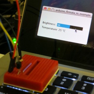
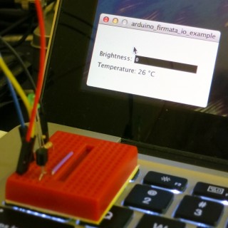
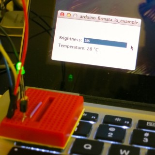
This might not look like much, but it was a lot of work to get here. It’s the display from a small Processing sketch, running on a Raspberry Pi, talking to an Arduino controlling the brightness of an LED with the slider, and reading from an LM35 temperature sensor.

I wanted to see if I could get graphical control of an Arduino on the Raspberry Pi. I wrote about the simplest sketch in Processing that combined output (to control a small green LED through a resistor) and input (from an LM35, that simplest of sensors). This is how it looks running on a slightly faster machine than the Raspberry Pi:

LED at half brightness, LM35 showing 25°C

LED off, sensor at 26°C

LED full on, LM35 warmed up

I had the same results on the Raspberry Pi; just much, much slower. The sketch is below the fold.

Running Processing on Raspberry Pi

Processing is both written in and generates Java, so there’s some hope that it can run on most platforms. Up-to-date installation instructions. These instructions are modified from Processing sur Raspberry Pi, for which thanks are given to the original author:

  1. Install the JDK and Java serial library: sudo apt-get install librxtx-java openjdk-6-jdk
  2. Download the Linux version of Processing, and unpack it to somewhere permanent in your home directory
  3. Delete the java folder in the Processing directory; for me, that was processing-1.5.1/java
  4. Replace that java folder with a link to your system’s installation: ln -s /usr/lib/jvm/java-6-openjdk-armhf java
  5. In the Processing folder, remove or rename modes/java/libraries/serial/library/linux32/librxtxSerial.so; it’s an x86 binary, and will fail
  6. In the Processing folder, also remove modes/java/libraries/serial/library/RXTXcomm.jar, and replace it with a copy of /usr/share/java/RXTXcomm.jar
    (If you don’t do this, you’ll get a warning: “WARNING:  RXTX Version mismatch”, and any serial comms will fail.)
  7. Download and install the controlP5 library for Processing
  8. Download and install the Arduino library for Processing
  9. Program your Arduino with Firmata; the version that comes with the Arduino software is fine a bit old.
  10. Connect your Arduino to the Raspberry Pi with a USB cable; it may require external power.

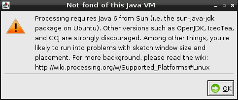
Now fire up Processing. It will used to take a while to start up, and will throw the following warning:

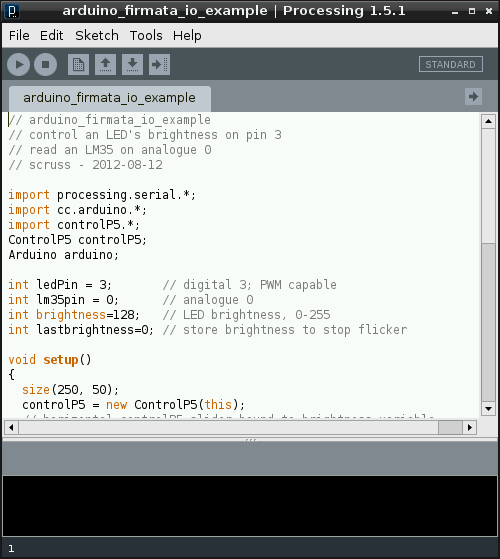
Despite this, it should eventually should start up fine:

Now, this is slow. It takes tens of seconds to start up. It might not be the most practical development tool, but Processing sketches are very portable, so you can develop on one machine, and then run on the Raspberry Pi.

The code at the end of this article expects:

  • an Arduino running the Firmata DAQ sketch attached to a USB port;
  • a small LED connected from digital pin 3, through a 1kΩ resistor to ground;
  • an LM35 with the following connections: +Vs → +5V, Vout → analogue pin 0, and GND → GND.

If you run this, after about half a minute, the blank sketch window appears, and about half a minute later, the slider and temperature reading appears. If it doesn’t, there’s a good chance that the serial libraries are wrong. Try this sketch:

import processing.serial.*;
import cc.arduino.*;

Arduino arduino;
println(Arduino.list());

This should return a number and a serial port where the Arduino was found; something like ‘[0] /dev/ttyACM0’.

What I really want to do now is get this same hardware running with Python and tkinter. It’s not that Python’s my favourite language; it’s just that the Raspberry Pi Foundation chose Python as the official language for the board. I’d rather work to further the aims of this educational foundation rather than work against it. Processing’s pretty much unworkably slow on the Raspberry Pi — but it does work!

Ontario Hamfest yesterday

Glad I went to the Ontario Hamfest yesterday — I won the Superprize! It is quite super; it’s an ICOM V80 2m HT. Built like an absolute tank; it feels heavier than my Kenwood TH-D72. Thanks to Burlington Amateur Radio Club for organizing the event, and to Radioworld for donating the prizes.

(If I want to get a little grinchy on this, the prize ticket said it was going to be a V82, a much pricier dualband HT, but hey! a free radio …)

It was an enjoyable event, if small by comparison to Hamvention, but then, everything is. Was pleased to see an Arduino/µC vendor at the show – Bill, of Aztec MCU Prototyping. Bill had some of his Omega MCU Systems boards for sale, which mostly feature ZIF sockets for rapid prototyping. I bought the Arduino-compatible (in software, if not pinout) Omega-328U board, and the PICAXE-based D-Axe. So that means I have even more types of µCs to learn!

knock yourselves out, guys …

I’m not quite sure why anyone would want to use the sort-of Arduino-compatible HamStack — billed as a microcontroller platform especially for amateur radio operators —in preference to developing amateur radio applications for Arduino, but chacun à son thingy. The PIC-based [I’d link to the PIC info page, but Microchip is giving me an internal server error] platform may have a few more IO pins than the stock Arduino, but:

  • development tools are expensive
  • there’s no cross-platform support
  • no direct USB support, either.

Some folks may already have gone to the expense of a PIC-based toolchain, but for beginners, it could be prohibitive. Maybe better to develop and improve radio applications for Arduino.

signals

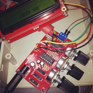
Built a simple Function Generator with Frequency Counter over the last couple of nights. It’s pretty basic — 0-~500kHz, 0-12V, Sine or Triangular waves — but good enough for my test needs. The frequency counter is basically an Arduino repackaged to feed the attached LCD. The counter isn’t super accurate, but is within 1% of what my multimeter says.

The kit has a fairly high voltage requirement for DC (>= 15V), but this was solved by a quick trip to Active Surplus. $11 bought me a 15V power supply (which delivers around 19V open circuit) and the right kind of barrel jack.

(Talking of neater meters, I didn’t know mine could support the Bluetooth Adaptor reviewed here. Dad’s old Avo couldn’t do that!)

K3NG Keyer complete

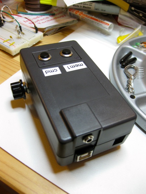
I finally build K3NG’s Arduino CW Keyer and put it in a nice box. Here’s how it looks:

K3NG Arduino keyer, complete

That’s a SparkFun Arduino Project Enclosure with two buttons (one command, one macro), a CW speed control potentiometer, and a simple 3.5mm audio jack for keying the transmitter.

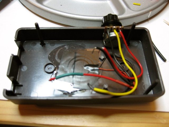
Enclosure base, showing piezo and potentiometer

I’ve glued a cheapo piezo (UHU All Purpose glue is my piezo glue of choice; cyanoacrylate is too brittle) onto the base, and cut a hole in the side for the speed pot. The piezo gives a clear enough side tone that I can copy CW (or Hellschreiber, as before) with audio output into Fldigi. The beeper’s got a fierce third harmonic, but that’s part of its charm. K3NG has a more complex speaker circuit, but this is simple and self-contained.

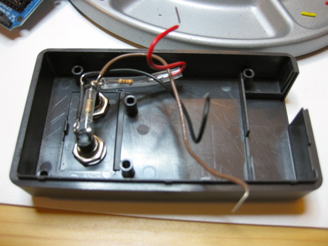
Enclosure lid, with buttons and resistors

Two momentary switches ($2 from Active Surplus) make up the control interface.

Arduino+Protoboard, and the magic of a 2N2222 switch

The clever bit is an Arduino Duemilanove Uno (my oldest board; it deserves a proper useful home which doesn’t seem to have the serial startup problems my Duemilanove had) with an Adafruit Proto Shield on top. The only “clever” componentry on that is a solitary 2N2222 switching transistor.

It works pretty well. The only thing that doesn’t seem to be stable is the memory button; it seems to choose randomly from any of the first four memories, so I might accidentally send an SK when I meant a CQ. For now, until I work out what’s wrong, I’ll stick to keyboard input of the macros.

K3NG Arduino Keyer

I’m pretty amazed that the above image is even vaguely readable. It’s Hellschreiber, generated by Anthony K3NG Good’s Arduino CW Keyer. What you’re seeing, though, is Hellschreiber from the keyer’s sidetone generator being fed through a piezo glued to a paper cup (and not just any paper cup) being picked up by Fldigi on my laptop’s microphone. This isn’t what you’d call a quality signal path, and it’s a tribute to the mode’s robustness that it can be made out at all.

Anthony has packed an absurd amount into this keyer. There isn’t enough memory on a stock 32K Arduino for all the features to be enabled. I’m planning to use it as a CW keyer alongside Fldigi as the decoder. Despite all the features that can be built in, I’d just be using it as a serial to Morse converter, with perhaps a couple of memory keys for calling CQ and the like.

I do have a slight problem with it while it’s breadboarded, though. The wiring’s so sensitive that the control circuit triggers if I put my hand near it, let alone touch the command button. I’ll have to do something about that. I can’t breadboard for toffee.

on the trail of the elusive Power Cost Monitor signal

Catherine probably thought I was acting no more strangely than usual last night, when I was holding the Power Cost display unit in one hand, frobbing the electric stove control with the other, all the while watching a digital clock and cackling gently to myself.

All this makes me think I’m a bit further on with getting something from the Power Cost Monitor. Previous attempts using cheap wireless units (and cluelessness on my part — never forget that) got nothing, so I caved and bought the rather expensive but nice Parallax 433 MHz RF Transceiver from Solarbotics.

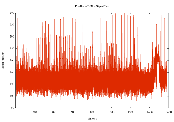
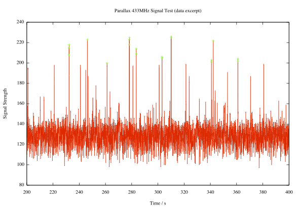
The Parallax unit adds an analogue output that’s proportional to the instantaneous signal strength. I hooked up the output to the trusty sdfatlib analogue logger, set the logger to sample every 50ms (figuring that, every now and again, it’s going to see part of a transmission) and this is what I saw:

Pretty noisy, I know. But look, there are regular peaks:

Here I’ve highlighted all the peaks with signal strength ≥ 200 (in arbitrary units, where 1024 would be full scale). It’s pretty regular; the largest peaks come in a shade under every 32 seconds, or a multiple thereof. If you need additional decimal places to validate your worldview, I’m thinking the period’s around 31.86s.

Observations made during last night’s frobbing and cackling episode seem to confirm that the display updates about every 32s. If you adjust the load mid-cycle, nothing changes until the update. If the display misses an update, it’ll refresh in 64 or 96 seconds.

I don’t yet know what bitrate the data comes through at, or the protocol. I’ve logged some data recorded at various rates: 433mhz_powercost_data. The file names give a hint at the data rate; L1200V04 was recorded at 1200bps, for example. I’m guessing that there’s some kind of sync header, then the total value and the current temperature (which was around/below freezing at the time). I need to work on that.

Update: I rewrote the logger to use the Arduino’s internal UART, since — lovely though NewSoftSerial may be — it causes millis() to report wildly inaccurate times at low bit rates. I recorded a bunch more data (powercost-arduino2.zip) in a slightly more useful text format. It has three columns:

  • the time, in milliseconds, at which the record was recorded
  • the time difference between this and the previous record, in milliseconds. Maybe not as useful as it could be. If adjacent records are about 31860ms apart, they’re transmissions from the meter.
  • 120 bytes of data recorded at the current bit rate (given in the file name) encoded in hex.

I’ve also included the Arduino sketch, which could be better documented.

Life with Ardweeny

I’m pretty new to Arduino, and electronics in general. Sure, I used to wire up sensors to a bunch of dataloggers, but there wasn’t much variation or application of theory. I made up a bunch of Ardweenies, mostly to practice soldering skills, but now I’ve made them, I might as well use them.

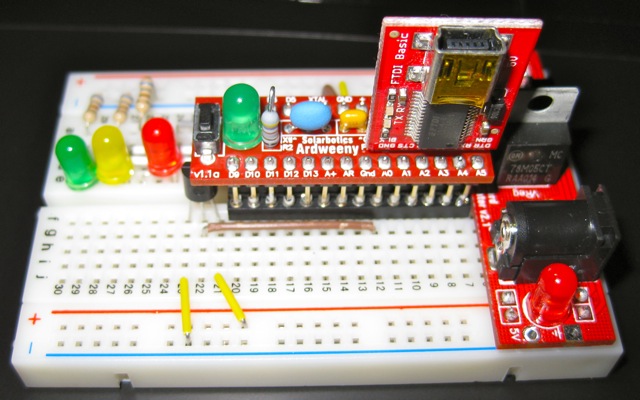
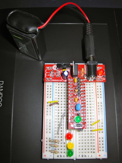
ardweeny, breadboard, USB programmer and PSU

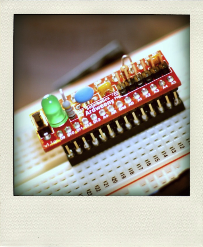
The Ardweeny is a tiny broadboard-only Arduino-compatible microcontroller board. It needs both a power supply and a means of programming it. Solarbotics’ own Breadboard Voltage Regulator Kit provides the juice, while a SparkFun’s FTDI Basic Breakout handles the USB serial programming. The FTDI breakout board can supply power, so I turn the power off to the board at the regulator when programming it. You can’t use shields with the Ardweeny, but it’s small enough that you can have a simple project on a small breadboard. It communicates with the Arduino IDE as if it were a Duemilanove.

The Ardweeny has pins clearly (if tinily) marked by function. To power it, you need to feed GND and +. The familiar A0-A5 and D0-D13 are present, if not quite where you’d expect them. There isn’t room to mark the digital pins capable of PWM.

For no particular reason (perhaps that spring finally looks like it might be warming things up around here) I wanted to make a a temperature sensor that would sample the temperature at start up, then warn if the temperature got more than 2°C hotter or colder.

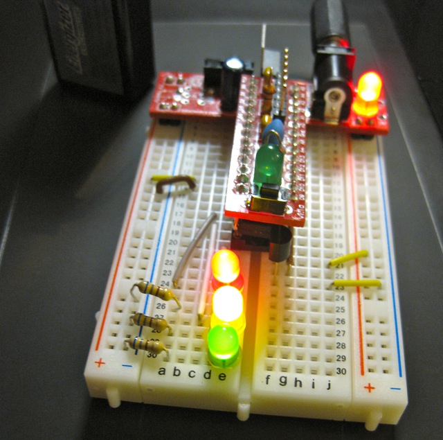
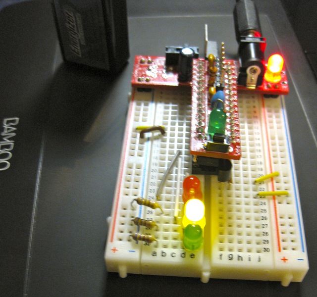
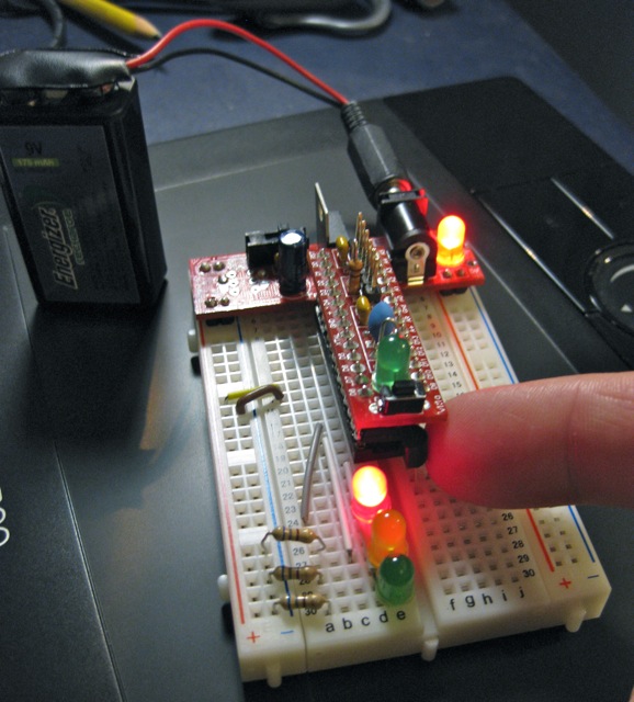
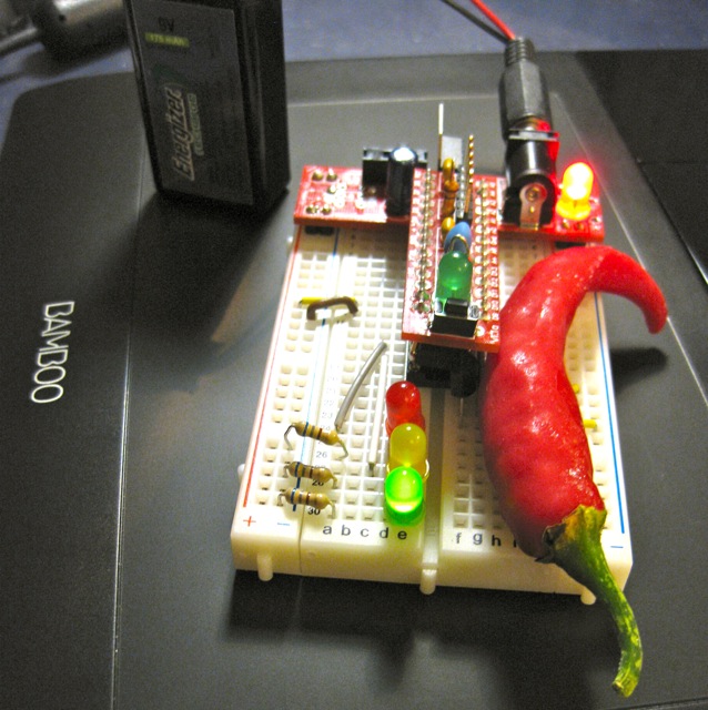
I used an LM35 as the sensor. These are a bit noisy, so I added some smoothing (nicked, with little grace, from the Arduino – Smoothing tutorial). The temperature is indicated by three LEDs: red for ≥2°C over, amber for within ±2°C of the starting temperature, and green for ≥2°C under. I also wanted all the LEDs lit while the system was working out starting temperature. Here’s how it runs:

starting up, showing all LEDs
showing normal temperature
warmed by a finger, showing ≥2°C over normal
chilled by a frozen cayenne (!), showing ≥2°C below normal

I put the LM35 on A0, and the red, amber and green LEDs on D5, D6 & D8. The only reason I didn’t use D7 was that I didn’t have the right length jumper wire. 680Ω resistors are used to limit current through the LEDs.

Here’s the code:

/*
 lm35_plusminus - read temperature at startup then light
 leds if over or under
 
 lm35 - analogue 0
 
 red led - digital 5
 amber led - digital 6
 green led - digital 8
 
 scruss - 2011-02-17
 */

#define REDPIN 5
#define AMBERPIN 6
#define GREENPIN 8
#define TEMPPIN 0 // analogue
#define DELTA 2.0 // amount +/- from start to warn
#define READINGS 15

//declare variables
float tempC, start_temp, array[READINGS], total;
int val, i;

void setup()
{
  pinMode(REDPIN, OUTPUT);
  pinMode(AMBERPIN, OUTPUT);
  pinMode(GREENPIN, OUTPUT);

  // signal start of test by lighting all LEDs
  digitalWrite(REDPIN, HIGH);
  digitalWrite(AMBERPIN, HIGH);
  digitalWrite(GREENPIN, HIGH);

  // read initial values
  for (i=0; i< READINGS; i++) {
    delay(500/READINGS); // just so initialization is visible
    val = analogRead(TEMPPIN);
    array[i] =  (5.0 * (float) val * 100.0)/1024.0;
    total += array[i];
  }
  start_temp = total / READINGS;

  // test off, lights off
  digitalWrite(REDPIN, LOW);
  digitalWrite(AMBERPIN, LOW);
  digitalWrite(GREENPIN, LOW);
  i=0; // just to initialize  
}

void loop()
{
  // some cheapo smoothing copied from the Smoothing example 
  //  in the playground
  total -= array[i];
  val = analogRead(TEMPPIN);
  tempC = (5.0 * (float) val * 100.0)/1024.0;
  array[i] = tempC;
  total += tempC;
  i++;
  if (i>=READINGS) {
    i=0;
  }
  tempC = total/READINGS;
  if (tempC - start_temp >= DELTA) {
    // we're hot !
    digitalWrite(REDPIN, HIGH);
    digitalWrite(AMBERPIN, LOW);
    digitalWrite(GREENPIN, LOW);
  }
  else if (tempC - start_temp <= -DELTA) {
    // we're cold !
    digitalWrite(REDPIN, LOW);
    digitalWrite(AMBERPIN, LOW);
    digitalWrite(GREENPIN, HIGH);
  }
  else {
    // we're just right !
    digitalWrite(REDPIN, LOW);
    digitalWrite(AMBERPIN, HIGH);
    digitalWrite(GREENPIN, LOW);
  }
}

Despite the smoothing, the LEDs flicker briefly as they turn on. I kind of like the effect, so I made no attempt to change it.

What I like about Arduino is that — within the limits of my sensor knowledge — the programming language does what I expect. The above program worked first time; worked, that is, save for me putting one LED in the wrong way round, so it didn’t light. I know I could probably replicate the same function with a few linear devices and other components, but it would take much more time and effort. It may not be the most elegant, but it does work,  and gives me the satisfaction of the desired result quickly.

big trouble in little microSD

It was a bit of a fight to get the SparkFun microSD Shield working. At first, I thought it was my choice of cards. Then, on reading the manual (ahem), I discovered the section “I downloaded a FAT library for Arduino on my own from the Web but it’s not working! Why not?“. It seems that the SparkFun shield uses non-standard pins for signalling, which they consider a feature, but some consider a bug.

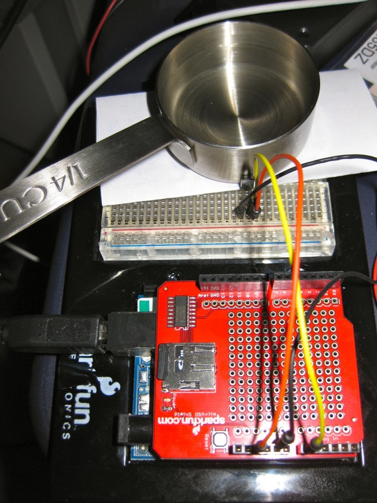
After fixing the code in the awesome sdfatlib library, I’ve now got it logging the temperature of a cooling container of hot water:

You might just be able to make out the LM35 pressed up against the measuring cup.
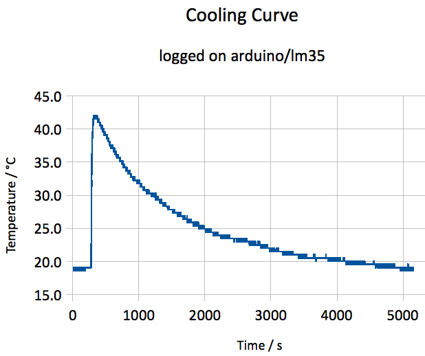
I remember making a right mess of this experiment in my school final Physics practical exam. I also used to do this in my first job when bored testing Campbell CR10 dataloggers, making a nice 1-d cooling curve with a thermocouple and a cup of hot water.

I think the heating came on a couple of times, as there shouldn’t be bumps in the curve. Here’s the data.

… that our fries were still there

Following on from this, here’s another anthem performed by the Five Guys and the Arduino Micro Cup Orchestra:

Converted from a midi file found at American and Patriotic Midi Music (unsurprising caution: autoplay midi music therein) to RTTL using MIDI to RTTL.

If you just want the source, here it is:

star-spang:d=4,o=5,b=80:2p,8f.,16d,a#4,d,f,2a#,8d.6,16c6,a#,d,e,2f,8f,8f,d.6,8c6,a#,2a,8g,8a,a#,a#,f,d,a#4,8f.,16d,a#4,d,f,2a#,8d.6,16c6,a#,d,e,2f,8f,8f,d.6,8c6,a#,2a,8g,8a,a#,a#,f,d,a#4,8d6,8d6,d6,d#6,f6,2f6,8d#6,8d6,c6,d6,d#6,2d#6,d#6,d.6,8c6,a#,2a,8g,8a,a#,d,e,2f,f,a#,a#,8a#,8a,g,g,g,c6,8d#6,8d6,8c6,8a#,a#,a,8f,8f,a#.,8c6,8d6,8d#6,2f6,8a#,8c6,d.6,8d#6,c6,1a#