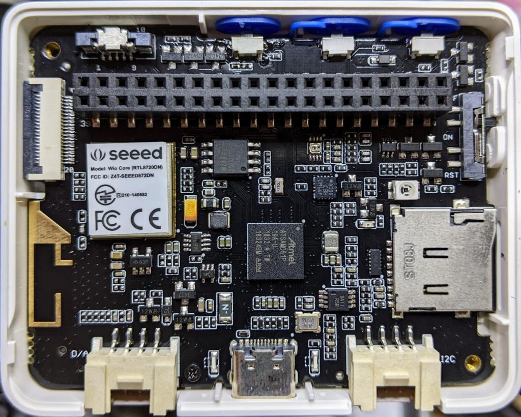
A while back, Seeed Studio sent me one of their Wio Terminal devices to review. It was pretty neat, but being limited to using Arduino to access all of it features was a little limiting. I still liked it, though, and wrote about it here: SeeedStudio Wio Terminal
There wasn’t any proper MicroPython support for the device as it used a MicroChip/Atmel SAMD51 ARM® Cortex®-M4 micro-controller. But since I wrote the review, one developer (robert-hh) has worked almost entirely solo to make SAMD51 and SAMD21 support useful in mainline MicroPython.
Hey! Development is still somewhere between “not quite ready for prime time” and “beware of the leopard”. MicroPython on the SAMD51 works remarkably well for supported boards, but don’t expect this to be beginner-friendly yet.
I thought I’d revisit the Wio Terminal and see what I could do using a nightly build (downloaded from Downloads – Wio Terminal D51R – MicroPython). Turns out, most of the board works really well!
What doesn’t work yet
- Networking/Bluetooth – this is never going to be easy, especially with Seeed Studio using a separate RTL8720 SoC. It may not be entirely impossible, as previously thought, but so far, wifi support seems quite far away
- QSPI flash for program storage –
this is not impossible, just not implemented yetthis works now too, but it’s quite slow since it relies on a software SPI driver. More details: samd51: MicroPython on the Seeed Wio Terminal · Discussion #9838 · micropython - RTC –
this is a compile-time option, but isn’t available on the stock images. Not all SAMD51 boards have a separate RTC oscillator, and deriving the RTC from the system oscillator would be quite wobbly.RTC works now! It may even be possible to provide backup battery power and have it keep time when powered off. VBAT / PB03 / SPI_SCK is broken out to the 40-pin connector.
What does work
- Display – ILI9341 320×240 px, RGB565 via SPI
- Accelerometer – LIS3DHTR via I²C
- Microphone – analogue
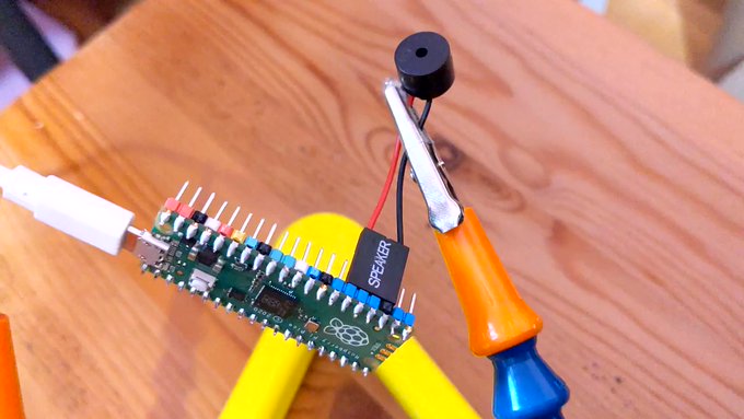
- Speaker – more like a buzzer, but this little PWM speaker element does allow you to play sounds
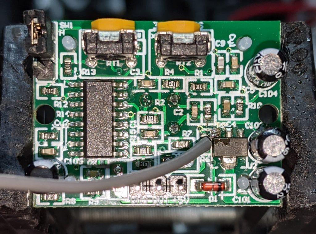
- Light Sensor – via analogue photo diode
- IR emitter – PWM, not tied to any hardware protocol
- Internal LED – a rather faint blue thing, but useful for low-key signalling
- Micro SD Card – vi SPI. Works well with MicroPython’s built-in virtual file systems
- Switches and buttons – three buttons on the top, and a five-way mini-joystick
- I²C via Grove Connector – a second, separate I²C channel.
I’ll go through each of these here, complete with a small working example.
LED
Let’s start with the simplest feature: the tiny blue LED hidden inside the case. You can barely see this, but it glows out around the USB C connector on the bottom of the case.
- MicroPython interfaces: machine.Pin, machine.PWM
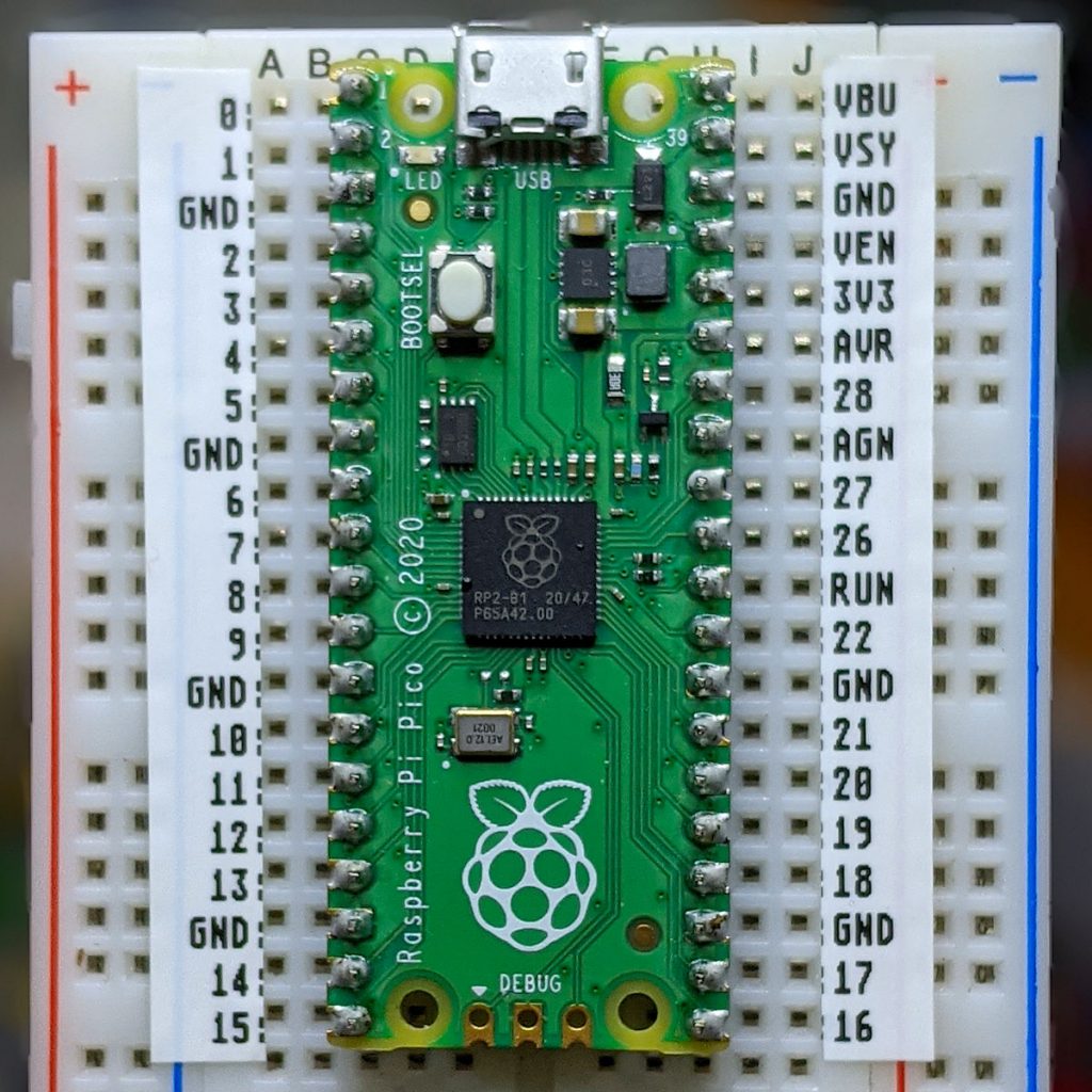
- Control pin: Pin(“LED_BLUE”) or Pin(15), or Pin(“PA15”): any one of these would work.
Example: Wio-Terminal-LED.py
# MicroPython / Seeed Wio Terminal / SAMD51
# Wio-Terminal-LED.py - blink the internal blue LED
# scruss, 2022-10
# -*- coding: utf-8 -*-

from machine import Pin
from time import sleep_ms

led = Pin("LED_BLUE", Pin.OUT)  # or Pin(15) or Pin("PA15")

try:
    while True:
        led.value(not led.value())
        sleep_ms(1200)
except:
    led.value(0)  # turn it off if user quits
    exit()
IR LED
I don’t have any useful applications of the IR LED for device control, so check out Awesome MicroPython’s IR section for a library that would work for you.
- MicroPython interfaces: machine.PWM
- Control pin: Pin(“PB31”)
Example: Wio-Terminal-IR_LED.py
# MicroPython / Seeed Wio Terminal / SAMD51
# Wio-Terminal-IR_LED.py - blink the internal IR LED
# scruss, 2022-10
# -*- coding: utf-8 -*-

# Hey! This is a completely futile exercise, unless you're able
# to see into the IR spectrum. But we're here to show you the pin
# specification to use. For actual useful libraries to do stuff with
# IR, take a look on https://awesome-micropython.com/#ir

# So this is a boring blink, 'cos we're keeping it short here.
# You might be able to see the LED (faintly) with your phone camera

from machine import Pin, PWM
from time import sleep_ms

ir = PWM(Pin("PB31"))  # "IR_CTL" not currently defined

try:
    while True:
        ir.duty_u16(32767)  # 50% duty
        ir.freq(38000)  # fast flicker
        sleep_ms(1200)
        ir.duty_u16(0)  # off
        sleep_ms(1200)
except:
    ir.duty_u16(0)  # turn it off if user quits
    exit()
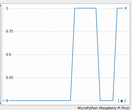
Buttons
There are three buttons on top, plus a 5-way joystick on the front. Their logic is inverted, so they read 0 when pressed, 1 when not. It’s probably best to use machine.Signal with these to make operation more, well, logical.
- MicroPython interface: machine.Signal (or machine.Pin)
- Control pins: Pin(“BUTTON_3”) or Pin(92) or Pin(PC28) – top left; Pin(“BUTTON_2”) or Pin(91) or Pin(PC27) – top middle; Pin(“BUTTON_1”) or Pin(90) or Pin(PC26) – top right; Pin(“SWITCH_B”) or Pin(108) or Pin(PD12) – joystick left; Pin(“SWITCH_Y”) or Pin(105) or Pin(PD09) – joystick right; Pin(“SWITCH_U”) or Pin(116) or Pin(PD20) – joystick up; Pin(“SWITCH_X”) or Pin(104) or Pin(PD08) – joystick down; Pin(“SWITCH_Z”) or Pin(106) or Pin(PD10) – joystick button
Example: Wio-Terminal-Buttons.py
# MicroPython / Seeed Wio Terminal / SAMD51
# Wio-Terminal-Buttons.py - test the buttons
# scruss, 2022-10
# -*- coding: utf-8 -*-

# using Signal because button sense is inverted: 1 = off, 0 = on
from machine import Pin, Signal
from time import sleep_ms

pin_names = [
    "BUTTON_3",  # Pin(92)  or Pin(PC28) - top left
    "BUTTON_2",  # Pin(91)  or Pin(PC27) - top middle
    "BUTTON_1",  # Pin(90)  or Pin(PC26) - top right
    "SWITCH_B",  # Pin(108) or Pin(PD12) - joystick left
    "SWITCH_Y",  # Pin(105) or Pin(PD09) - joystick right
    "SWITCH_U",  # Pin(116) or Pin(PD20) - joystick up
    "SWITCH_X",  # Pin(104) or Pin(PD08) - joystick down
    "SWITCH_Z",  # Pin(106) or Pin(PD10) - joystick button
]

pins = [None] * len(pin_names)
for i, name in enumerate(pin_names):
    pins[i] = Signal(Pin(name, Pin.IN), invert=True)

while True:
    for i in range(len(pin_names)):
        print(pins[i].value(), end="")
    print()
    sleep_ms(100)
Buzzer
A very quiet little PWM speaker.
- MicroPython interfaces: machine.PWM
- Control pin: Pin(“BUZZER”) or Pin(107) or Pin(“PD11”)
Example: Wio-Terminal-Buzzer.py
# MicroPython / Seeed Wio Terminal / SAMD51
# Wio-Terminal-Buzzer.py - play a scale on the buzzer with PWM
# scruss, 2022-10
# -*- coding: utf-8 -*-

from time import sleep_ms
from machine import Pin, PWM

pwm = PWM(Pin("BUZZER", Pin.OUT))  # or Pin(107) or Pin("PD11")
cmaj = [262, 294, 330, 349, 392, 440, 494, 523]  # C Major Scale frequencies

for note in cmaj:
    print(note, "Hz")
    pwm.duty_u16(32767)  # 50% duty
    pwm.freq(note)
    sleep_ms(225)
    pwm.duty_u16(0)  # 0% duty - silent
    sleep_ms(25)
Light Sensor
This is a simple photo diode. It doesn’t seem to return any kind of calibrated value. Reads through the back of the case.
- MicroPython interfaces: machine.ADC
- Control pin: machine.ADC(“PD01”)
Example code: Wio-Terminal-LightSensor.py
# MicroPython / Seeed Wio Terminal / SAMD51
# Wio-Terminal-LightSensor.py - print values from the light sensor
# scruss, 2022-10
# -*- coding: utf-8 -*-

from time import sleep_ms
from machine import ADC

# PD15-22C/TR8 photodiode
light_sensor = ADC("PD01")

while True:
    print([light_sensor.read_u16()])
    sleep_ms(50)
Microphone
Again, a simple analogue sensor:
- MicroPython interfaces: machine.ADC
- Control pin: machine.ADC(“MIC”)
Example: Wio-Terminal-Microphone.py
# MicroPython / Seeed Wio Terminal / SAMD51
# Wio-Terminal-Microphone.py - print values from the microphone
# scruss, 2022-10
# -*- coding: utf-8 -*-

from time import sleep_ms
from machine import ADC

mic = ADC("MIC")

while True:
    print([mic.read_u16()])
    sleep_ms(5)
Grove I²C Port
The Wio Terminal has two Grove ports: the one on the left (under the speaker port) is an I²C port. As I don’t know what you’ll be plugging in there, this example does a simple bus scan. You could make a, appalling typewriter if you really wanted.
- MicroPython interfaces: machine.I2C (channel 3), machine. Pin
- Control pins: scl=Pin(“SCL1”), sda=Pin(“SDA1”)
Example: Wio-Terminal-Grove-I2C.py
# MicroPython / Seeed Wio Terminal / SAMD51
# Wio-Terminal-Grove-I2C.py - show how to connect on Grove I2C
# scruss, 2022-10
# -*- coding: utf-8 -*-

from machine import Pin, I2C

# NB: This doesn't do much of anything except list what's
# connected to the left (I²C) Grove connector on the Wio Terminal

i2c = I2C(3, scl=Pin("SCL1"), sda=Pin("SDA1"))
devices = i2c.scan()

if len(devices) == 0:
    print("No I²C devices connected to Grove port.")
else:
    print("Found these I²C devices on the Grove port:")
    for n, id in enumerate(devices):
        print(" device", n, ": ID", id, "(hex:", hex(id) + ")")
LIS3DH Accelerometer
This is also an I²C device, but connected to a different port (both logically and physically) than the Grove one.
- MicroPython interfaces: machine.I2C (channel 4), machine. Pin
- Control pins: scl=Pin(“SCL0”), sda=Pin(“SDA0”)
- Library: from MicroPython-LIS3DH, copy lis3dh.py to the Wio Terminal’s small file system. Better yet, compile it to mpy using mpy-cross to save even more space before you copy it across
Example: Wio-Terminal-Accelerometer.py (based on tinypico-micropython/lis3dh library/example.py)
# MicroPython / Seeed Wio Terminal / SAMD51
# Wio-Terminal-Accelerometer.py - test out accelerometer
# scruss, 2022-10
# -*- coding: utf-8 -*-
# based on
#  https://github.com/tinypico/tinypico-micropython/tree/master/lis3dh%20library

import lis3dh, time, math
from machine import Pin, I2C

i2c = I2C(4, scl=Pin("SCL0"), sda=Pin("SDA0"))
imu = lis3dh.LIS3DH_I2C(i2c)

last_convert_time = 0
convert_interval = 100  # ms
pitch = 0
roll = 0

# Convert acceleration to Pitch and Roll
def convert_accell_rotation(vec):
    x_Buff = vec[0]  # x
    y_Buff = vec[1]  # y
    z_Buff = vec[2]  # z

    global last_convert_time, convert_interval, roll, pitch

    # We only want to re-process the values every 100 ms
    if last_convert_time < time.ticks_ms():
        last_convert_time = time.ticks_ms() + convert_interval

        roll = math.atan2(y_Buff, z_Buff) * 57.3
        pitch = (
            math.atan2((-x_Buff), math.sqrt(y_Buff * y_Buff + z_Buff * z_Buff)) * 57.3
        )

    # Return the current values in roll and pitch
    return (roll, pitch)


# If we have found the LIS3DH
if imu.device_check():
    # Set range of accelerometer (can be RANGE_2_G, RANGE_4_G, RANGE_8_G or RANGE_16_G).
    imu.range = lis3dh.RANGE_2_G

    # Loop forever printing values
    while True:
        # Read accelerometer values (in m / s ^ 2).  Returns a 3-tuple of x, y,
        # z axis values.  Divide them by 9.806 to convert to Gs.
        x, y, z = [value / lis3dh.STANDARD_GRAVITY for value in imu.acceleration]
        print("x = %0.3f G, y = %0.3f G, z = %0.3f G" % (x, y, z))

        # Convert acceleration to Pitch and Roll and print values
        p, r = convert_accell_rotation(imu.acceleration)
        print("pitch = %0.2f, roll = %0.2f" % (p, r))

        # Small delay to keep things responsive but give time for interrupt processing.
        time.sleep(0.1)
SD Card
- MicroPython interfaces: machine.SPI (channel 6), machine.Pin, machine.Signal
- Control Pins: Pin(“SD_SCK”), Pin(“SD_MOSI”), Pin(“SD_MISO”) for SD access. Pin(“SD_DET”) is low if an SD card is inserted, otherwise high
- Library: copy sdcard.py from micropython-lib to the Wio Terminal’s file system.
Rather than provide a small canned example (there’s one here, if you must: Wio-Terminal-SDCard.py) here’s my boot.py startup file, showing how I safely mount an SD card if there’s one inserted, but keep booting even if it’s missing:
# boot.py - MicroPython / Seeed Wio Terminal / SAMD51

import sys

sys.path.append("/lib")

import machine
import gc
import os
import sdcard

machine.freq(160000000)  # fast but slightly jittery clock
gc.enable()

# mount SD card if there's one inserted
try:
    sd_detected = machine.Signal(
        machine.Pin("SD_DET", machine.Pin.IN),
        invert=True,
    )
    sd_spi = machine.SPI(
        6,
        sck=machine.Pin("SD_SCK"),
        mosi=machine.Pin("SD_MOSI"),
        miso=machine.Pin("SD_MISO"),
        baudrate=40000000,
    )
    sd = sdcard.SDCard(sd_spi, machine.Pin("SD_CS"))
    if sd_detected.value() == True:
        os.mount(sd, "/SD")
        print("SD card mounted on /SD")
    else:
        raise Exception("SD card not inserted, can't mount /SD")
except:
    print("SD card not found")
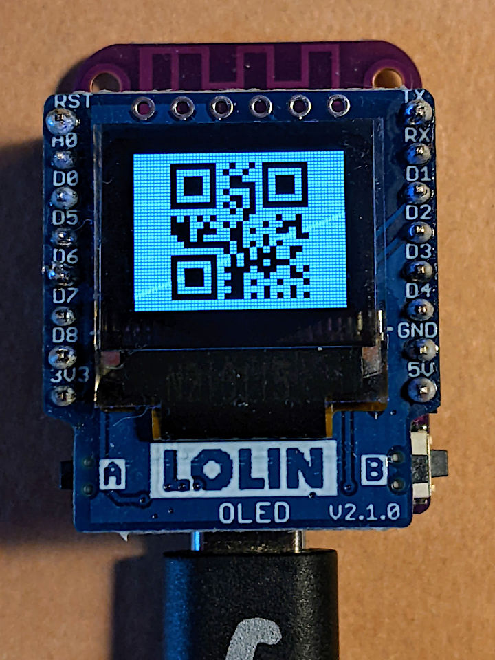
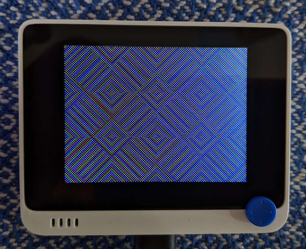
ILI9341 Display
I’m going to use the library rdagger/micropython-ili9341: MicroPython ILI9341Display & XPT2046 Touch Screen Driver because it’s reliable, and since it’s written entirely in MicroPython, it’s easy to install. It’s not particularly fast, though.
The Wio Terminal may have an XPT2046 resistive touch controller installed, but I haven’t been able to test it. There are LCD_XL, LCD_YU, LCD_XR and LCD_YD lines on the schematic that might indicate it’s there, though.
- MicroPython interfaces: machine.SPI (channel 7), machine.Pin.
- Control Pins: Pin(“LCD_SCK”), Pin(“LCD_MOSI”), Pin(“LCD_MISO”). Pin(“LED_LCD”) is the backlight control
- Library: copy ili9341.py from rdagger /micropython-ili9341 to the Wio Terminal’s file system.
This demo draws rainbow-coloured diamond shapes that change continuously.
Example: Wio-Terminal-Screen.py
# MicroPython / Seeed Wio Terminal / SAMD51
# Wio-Terminal-Screen.py - output something on the ILI9341 screen
# scruss, 2022-10
# -*- coding: utf-8 -*-


from time import sleep
from ili9341 import Display, color565
from machine import Pin, SPI


def wheel565(pos):
    # Input a value 0 to 255 to get a colour value.
    # The colours are a transition r - g - b - back to r.
    # modified to return RGB565 value for ili9341 - scruss
    (r, g, b) = (0, 0, 0)
    if (pos < 0) or (pos > 255):
        (r, g, b) = (0, 0, 0)
    if pos < 85:
        (r, g, b) = (int(pos * 3), int(255 - (pos * 3)), 0)
    elif pos < 170:
        pos -= 85
        (r, g, b) = (int(255 - pos * 3), 0, int(pos * 3))
    else:
        pos -= 170
        (r, g, b) = (0, int(pos * 3), int(255 - pos * 3))
    return (r & 0xF8) << 8 | (g & 0xFC) << 3 | b >> 3


# screen can be a little slow to turn on, so use built-in
# LED to signal all is well
led = Pin("LED_BLUE", Pin.OUT)

backlight = Pin("LED_LCD", Pin.OUT)  # backlight is not a PWM pin
spi = SPI(
    7, sck=Pin("LCD_SCK"), mosi=Pin("LCD_MOSI"), miso=Pin("LCD_MISO"), baudrate=4000000
)
display = Display(spi, dc=Pin("LCD_D/C"), cs=Pin("LCD_CS"), rst=Pin("LCD_RESET"))
display.display_on()
display.clear()
led.on()  # shotgun debugging, embedded style
backlight.on()

# use default portrait settings: x = 0..239, y = 0..319
dx = 3
dy = 4
x = 3
y = 4
i = 0

try:
    while True:
        # display.draw_pixel(x, y, wheel565(i))
        display.fill_hrect(x, y, 3, 4, wheel565(i))
        i = (i + 1) % 256
        x = x + dx
        y = y + dy
        if x <= 4:
            dx = -dx
        if x >= 234:
            dx = -dx
        if y <= 5:
            dy = -dy
        if y >= 313:
            dy = -dy
except:
    backlight.off()
    led.off()
    display.display_off()