This is almost too trivial to write up, as the TTP223 does exactly what you’d expect it to do with no other components.
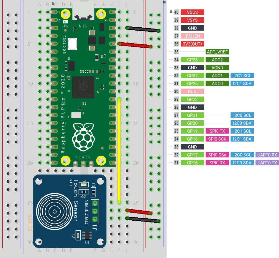
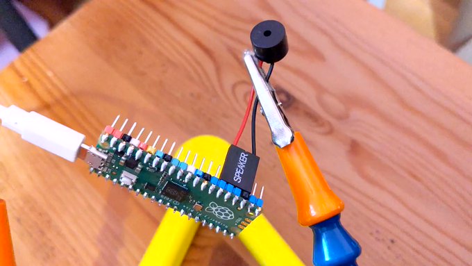
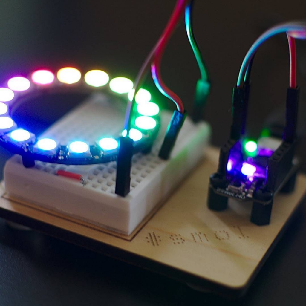
Breakout boards for the TTP223 capacitive touch sensor come in a whole variety of sizes. The ones I got from Simcoe DIY are much smaller, have a different connection order, and don’t have an indicator LED. What they all give you, though, is a single touch/proximity switch for about $1.50
Trivial code to light the Raspberry Pi Pico’s LED when a touch event is detected looks like this:
import machine
touch = machine.Pin(22, machine.Pin.IN)
led = machine.Pin(25, machine.Pin.OUT)

while True:
    led.value(touch.value())
For the default configuration, the sensor’s output goes high while a touch is detected, then goes low. This might not be the ideal configuration for you, so these sensor boards have a couple of solder links you can modify:
- Active Low — sometimes you want a switch to indicate a touch with a low / 0 V signal. On the boards I have, the A link controls that: put a blob of solder across it to reverse the switch’s sense.
- Toggle — if you want the output to stay latched at one level until you touch it again, a blob of solder across the T link will do that. Unlike a mechanical switch, this won’t stay latched after a power cycle, though.
And that’s all it does. Sometimes it’s nice to have a sensor that does exactly one thing perfectly well.