So you bought that Brother laser printer like everyone told you to. And now it’s out of toner, so you replaced the cartridge. If you were in the USA, you could return the cartridge for free using the included label. But in Canada … it’s a whole deal including registering with Brother and giving away your contact details and, and, and …
Anyway, my dear fellow Canadians, I went through the process and downloaded the label PDF so you don’t have to:
Stewart Russell – scruss.com — 2024-03-26, at age 19999 days …
Summary
One’s thousand day(s) celebration occurs every thousand days of a person’s life. They are meant to be a recognition of getting this far, and are celebrated at the person’s own discretion.
Who is this for?
Maybe your birthday’s on a day associated with an unpleasant event. Your thousand day will never coincide with your birthday.
Maybe your birthday’s in the middle of winter, or in another part of the year that you’re not keen on. Your thousand day is every 2 years and 3 seasons, so it shifts back by a season every time it happens.
Quantities and scale
1000 days is approximately:
2.738 years
2 years 269 days
2 years 8.85 months
2 years, 3 seasons.
4000 days is just shy of 11 years.
Disadvantages
Compared to regular birthdays, thousand days:
must be calculated; they’re not intuitive when they’re going to happen. But we have computers and calendar reminders for that …
can be used to work out your actual date of birth, if someone knows that you’re going to be x000 days old on a particular day. It’s possible to know someone’s birthday, but not know their age.
There are no trademarks, patents, official websites, social media or official anythings attached to this concept. Please take the idea and do good with it.
So why aren’t you implementing this further?
I’ve had this idea kicking around my head for at least the last 20 years. For $REASONS, it turns out I’m not very good at implementing stuff. I’d far rather someone else took this idea and ran with it than let it sit undeveloped.
This is a mini celebratory post to say that I’ve fixed the database encoding problems on this blog. It looks like I will have to go through the posts manually to correct the errors still, but at least I can enter, store and display UTF-8 characters as expected.
“? µ ° × — – ½ ¾ £ é?êè”, he said with some relief.
Postmortem: For reasons I cannot explain or remember, the database on this blog flipped to an archaic character set: latin1, aka ISO/IEC 8859-1. A partial fix was effected by downloading the entire site’s database backup, and changing all the following references in the SQL:
For additional annoyance, the entire SQL dump was too big to load back into phpmyadmin, so I had to split it by table. Thank goodness for awk!
#!/usr/bin/awk -f

BEGIN {
    outfile = "nothing.sql";
}

/^# Table: / {
    # very special comment in WP backup that introduces a new table
    # last field is table_name,
    # which we use to create table_name.sql
    t = $NF
    gsub(/`/, "", t);
    outfile = t ".sql";
}

{
    print > outfile;
}
The data still appears to be confused. For example, in the post Compose yourself, Raspberry Pi!, what should appear as “That little key marked “Compose”” appears as “That little key marked “Composeâ€Â”. This isn’t a straight conversion of one character set to another. It appears to have been double-encoded, and wrongly too.
Still, at least I can now write again and have whatever new things I make turn up the way I like. Editing 20 years of blog posts awaits … zzz
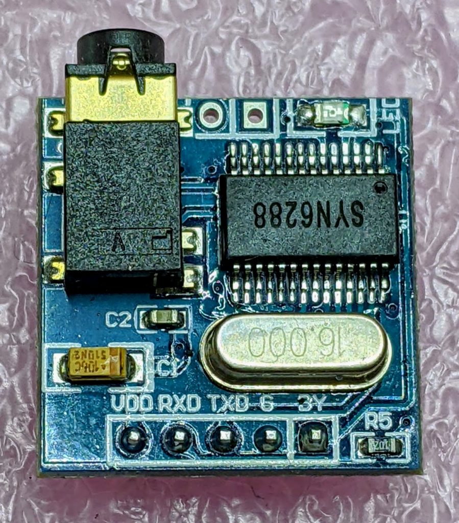
After remarkable success with the SYN-6988 TTS module, then somewhat less success with the SYN-6658 and other modules, I didn’t hold out much hope for the YuTone SYN-6288, which – while boasting a load of background tunes that could play over speech – can only convert Chinese text to speech
The wiring is similar to the SYN-6988: a serial UART connection at 9600 baud, plus a Busy (BY) line to signal when the chip is busy. The serial protocol is slightly more complicated, as the SYN-6288 requires a checksum byte at the end.
As I’m not interested in the text-to-speech output itself, here’s a MicroPython script to play all of the sounds:
# very crude MicroPython demo of SYN6288 TTS chip
# scruss, 2023-07
import machine
import time

### setup device
ser = machine.UART(
    0, baudrate=9600, bits=8, parity=None, stop=1
)  # tx=Pin(0), rx=Pin(1)

busyPin = machine.Pin(2, machine.Pin.IN, machine.Pin.PULL_UP)


def sendspeak(u2, data, busy):
    # modified from https://github.com/TPYBoard/TPYBoard_lib/
    # u2 = UART(uart, baud)
    eec = 0
    buf = [0xFD, 0x00, 0, 0x01, 0x01]
    # buf = [0xFD, 0x00, 0, 0x01, 0x79]  # plays with bg music 15
    buf[2] = len(data) + 3
    buf += list(bytearray(data, "utf-8"))
    for i in range(len(buf)):
        eec ^= int(buf[i])
    buf.append(eec)
    u2.write(bytearray(buf))
    while busy.value() != True:
        # wait for busy line to go high
        time.sleep_ms(5)
    while busy.value() == True:
        # wait for it to finish
        time.sleep_ms(5)


for s in "abcdefghijklmnopqrstuvwxy":
    playstr = "[v10][x1]sound" + s
    print(playstr)
    sendspeak(ser, playstr, busyPin)
    time.sleep(2)

for s in "abcdefgh":
    playstr = "[v10][x1]msg" + s
    print(playstr)
    sendspeak(ser, playstr, busyPin)
    time.sleep(2)

for s in "abcdefghijklmno":
    playstr = "[v10][x1]ring" + s
    print(playstr)
    sendspeak(ser, playstr, busyPin)
    time.sleep(2)
Each sound starts and stops with a very loud click, and the sound quality is not great. I couldn’t get a good recording of the sounds (some of which of which are over a minute long) as the only way I could get reliable audio output was through tiny headphones. Any recording came out hopelessly distorted:
I’m not too disappointed that this didn’t work well. I now know that the SYN-6988 is the good one to get. It also looks like I may never get to try the XFS5152CE speech synthesizer board: AliExpress has cancelled my shipment for no reason. It’s supposed to have some English TTS function, even if quite limited.
Here’s the auto-translated SYN-6288 manual, if you do end up finding a use for the thing
I have a bunch of other boards on order to see if the other chips (SYN6288, SYN6658, XF5152) work in the same way. I really wonder which I’ll end up receiving!
Update (2023-07-09): Got the SYN6658. It does not support English TTS and thus is not recommended. It does have some cool sounds, though.
Embedded Text Command Sound Table
The github repo references Embedded text commands, but all of the sound references was too difficult to paste into a table there. So here are all of the ones that the SYN-6988 knows about:
Name is the string you use to play the sound, eg: [x1]sound101
Alias is an alternative name by which you can call some of the sounds. This is for better compatibility with the SYN6288 apparently. So [x1]sound101 is exactly the same as specifying [x1]sounda
Type is the sound description from the manual. Many of these are blank
Link is a playable link for a recording of the sound.
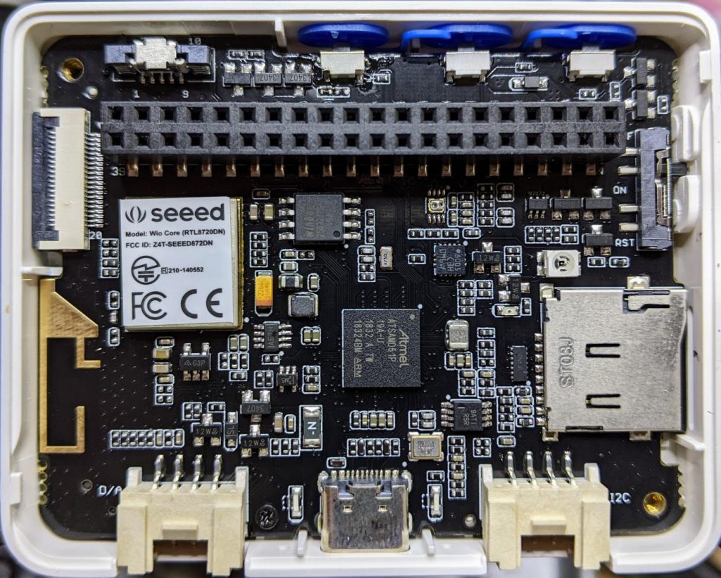
A while back, Seeed Studio sent me one of their Wio Terminal devices to review. It was pretty neat, but being limited to using Arduino to access all of it features was a little limiting. I still liked it, though, and wrote about it here: SeeedStudio Wio Terminal
Wio Terminal, doing a thing
There wasn’t any proper MicroPython support for the device as it used a MicroChip/Atmel SAMD51 ARM® Cortex®-M4 micro-controller. But since I wrote the review, one developer (robert-hh) has worked almost entirely solo to make SAMD51 and SAMD21 support useful in mainline MicroPython.
Hey! Development is still somewhere between “not quite ready for prime time” and “beware of the leopard”. MicroPython on the SAMD51 works remarkably well for supported boards, but don’t expect this to be beginner-friendly yet.
I thought I’d revisit the Wio Terminal and see what I could do using a nightly build (downloaded from Downloads – Wio Terminal D51R – MicroPython). Turns out, most of the board works really well!
What doesn’t work yet
Networking/Bluetooth – this is never going to be easy, especially with Seeed Studio using a separate RTL8720 SoC. It may not be entirely impossible, as previously thought, but so far, wifi support seems quite far away
RTC – this is a compile-time option, but isn’t available on the stock images. Not all SAMD51 boards have a separate RTC oscillator, and deriving the RTC from the system oscillator would be quite wobbly. RTC works now! It may even be possible to provide backup battery power and have it keep time when powered off. VBAT / PB03 / SPI_SCK is broken out to the 40-pin connector.
What does work
Display – ILI9341 320×240 px, RGB565 via SPI
Accelerometer – LIS3DHTR via I²C
Microphone – analogue
Speaker – more like a buzzer, but this little PWM speaker element does allow you to play sounds
Light Sensor – via analogue photo diode
IR emitter – PWM, not tied to any hardware protocol
Internal LED – a rather faint blue thing, but useful for low-key signalling
Micro SD Card – vi SPI. Works well with MicroPython’s built-in virtual file systems
Switches and buttons – three buttons on the top, and a five-way mini-joystick
I²C via Grove Connector – a second, separate I²C channel.
I’ll go through each of these here, complete with a small working example.
Inside the remarkably hard-to-open Wio Terminal
LED
Let’s start with the simplest feature: the tiny blue LED hidden inside the case. You can barely see this, but it glows out around the USB C connector on the bottom of the case.
MicroPython interfaces: machine.Pin, machine.PWM
Control pin: Pin(“LED_BLUE”) or Pin(15), or Pin(“PA15”): any one of these would work.
# MicroPython / Seeed Wio Terminal / SAMD51
# Wio-Terminal-LED.py - blink the internal blue LED
# scruss, 2022-10
# -*- coding: utf-8 -*-

from machine import Pin
from time import sleep_ms

led = Pin("LED_BLUE", Pin.OUT)  # or Pin(15) or Pin("PA15")

try:
    while True:
        led.value(not led.value())
        sleep_ms(1200)
except:
    led.value(0)  # turn it off if user quits
    exit()
IR LED
I don’t have any useful applications of the IR LED for device control, so check out Awesome MicroPython’s IR section for a library that would work for you.
# MicroPython / Seeed Wio Terminal / SAMD51
# Wio-Terminal-IR_LED.py - blink the internal IR LED
# scruss, 2022-10
# -*- coding: utf-8 -*-

# Hey! This is a completely futile exercise, unless you're able
# to see into the IR spectrum. But we're here to show you the pin
# specification to use. For actual useful libraries to do stuff with
# IR, take a look on https://awesome-micropython.com/#ir

# So this is a boring blink, 'cos we're keeping it short here.
# You might be able to see the LED (faintly) with your phone camera

from machine import Pin, PWM
from time import sleep_ms

ir = PWM(Pin("PB31"))  # "IR_CTL" not currently defined

try:
    while True:
        ir.duty_u16(32767)  # 50% duty
        ir.freq(38000)  # fast flicker
        sleep_ms(1200)
        ir.duty_u16(0)  # off
        sleep_ms(1200)
except:
    ir.duty_u16(0)  # turn it off if user quits
    exit()
Buttons
There are three buttons on top, plus a 5-way joystick on the front. Their logic is inverted, so they read 0 when pressed, 1 when not. It’s probably best to use machine.Signal with these to make operation more, well, logical.
Control pins: Pin(“BUTTON_3”) or Pin(92) or Pin(PC28) – top left; Pin(“BUTTON_2”) or Pin(91) or Pin(PC27) – top middle; Pin(“BUTTON_1”) or Pin(90) or Pin(PC26) – top right; Pin(“SWITCH_B”) or Pin(108) or Pin(PD12) – joystick left; Pin(“SWITCH_Y”) or Pin(105) or Pin(PD09) – joystick right; Pin(“SWITCH_U”) or Pin(116) or Pin(PD20) – joystick up; Pin(“SWITCH_X”) or Pin(104) or Pin(PD08) – joystick down; Pin(“SWITCH_Z”) or Pin(106) or Pin(PD10) – joystick button
# MicroPython / Seeed Wio Terminal / SAMD51
# Wio-Terminal-Buttons.py - test the buttons
# scruss, 2022-10
# -*- coding: utf-8 -*-

# using Signal because button sense is inverted: 1 = off, 0 = on
from machine import Pin, Signal
from time import sleep_ms

pin_names = [
    "BUTTON_3",  # Pin(92)  or Pin(PC28) - top left
    "BUTTON_2",  # Pin(91)  or Pin(PC27) - top middle
    "BUTTON_1",  # Pin(90)  or Pin(PC26) - top right
    "SWITCH_B",  # Pin(108) or Pin(PD12) - joystick left
    "SWITCH_Y",  # Pin(105) or Pin(PD09) - joystick right
    "SWITCH_U",  # Pin(116) or Pin(PD20) - joystick up
    "SWITCH_X",  # Pin(104) or Pin(PD08) - joystick down
    "SWITCH_Z",  # Pin(106) or Pin(PD10) - joystick button
]

pins = [None] * len(pin_names)
for i, name in enumerate(pin_names):
    pins[i] = Signal(Pin(name, Pin.IN), invert=True)

while True:
    for i in range(len(pin_names)):
        print(pins[i].value(), end="")
    print()
    sleep_ms(100)
Buzzer
A very quiet little PWM speaker.
MicroPython interfaces: machine.PWM
Control pin: Pin(“BUZZER”) or Pin(107) or Pin(“PD11”)
# MicroPython / Seeed Wio Terminal / SAMD51
# Wio-Terminal-Microphone.py - print values from the microphone
# scruss, 2022-10
# -*- coding: utf-8 -*-

from time import sleep_ms
from machine import ADC

mic = ADC("MIC")

while True:
    print([mic.read_u16()])
    sleep_ms(5)
Grove I²C Port
The Wio Terminal has two Grove ports: the one on the left (under the speaker port) is an I²C port. As I don’t know what you’ll be plugging in there, this example does a simple bus scan. You could make a, appalling typewriter if you really wanted.
# MicroPython / Seeed Wio Terminal / SAMD51
# Wio-Terminal-Grove-I2C.py - show how to connect on Grove I2C
# scruss, 2022-10
# -*- coding: utf-8 -*-

from machine import Pin, I2C

# NB: This doesn't do much of anything except list what's
# connected to the left (I²C) Grove connector on the Wio Terminal

i2c = I2C(3, scl=Pin("SCL1"), sda=Pin("SDA1"))
devices = i2c.scan()

if len(devices) == 0:
    print("No I²C devices connected to Grove port.")
else:
    print("Found these I²C devices on the Grove port:")
    for n, id in enumerate(devices):
        print(" device", n, ": ID", id, "(hex:", hex(id) + ")")
LIS3DH Accelerometer
This is also an I²C device, but connected to a different port (both logically and physically) than the Grove one.
Library: from MicroPython-LIS3DH, copy lis3dh.py to the Wio Terminal’s small file system. Better yet, compile it to mpy using mpy-cross to save even more space before you copy it across
# MicroPython / Seeed Wio Terminal / SAMD51
# Wio-Terminal-Accelerometer.py - test out accelerometer
# scruss, 2022-10
# -*- coding: utf-8 -*-
# based on
#  https://github.com/tinypico/tinypico-micropython/tree/master/lis3dh%20library

import lis3dh, time, math
from machine import Pin, I2C

i2c = I2C(4, scl=Pin("SCL0"), sda=Pin("SDA0"))
imu = lis3dh.LIS3DH_I2C(i2c)

last_convert_time = 0
convert_interval = 100  # ms
pitch = 0
roll = 0

# Convert acceleration to Pitch and Roll
def convert_accell_rotation(vec):
    x_Buff = vec[0]  # x
    y_Buff = vec[1]  # y
    z_Buff = vec[2]  # z

    global last_convert_time, convert_interval, roll, pitch

    # We only want to re-process the values every 100 ms
    if last_convert_time < time.ticks_ms():
        last_convert_time = time.ticks_ms() + convert_interval

        roll = math.atan2(y_Buff, z_Buff) * 57.3
        pitch = (
            math.atan2((-x_Buff), math.sqrt(y_Buff * y_Buff + z_Buff * z_Buff)) * 57.3
        )

    # Return the current values in roll and pitch
    return (roll, pitch)


# If we have found the LIS3DH
if imu.device_check():
    # Set range of accelerometer (can be RANGE_2_G, RANGE_4_G, RANGE_8_G or RANGE_16_G).
    imu.range = lis3dh.RANGE_2_G

    # Loop forever printing values
    while True:
        # Read accelerometer values (in m / s ^ 2).  Returns a 3-tuple of x, y,
        # z axis values.  Divide them by 9.806 to convert to Gs.
        x, y, z = [value / lis3dh.STANDARD_GRAVITY for value in imu.acceleration]
        print("x = %0.3f G, y = %0.3f G, z = %0.3f G" % (x, y, z))

        # Convert acceleration to Pitch and Roll and print values
        p, r = convert_accell_rotation(imu.acceleration)
        print("pitch = %0.2f, roll = %0.2f" % (p, r))

        # Small delay to keep things responsive but give time for interrupt processing.
        time.sleep(0.1)
Control Pins: Pin(“SD_SCK”), Pin(“SD_MOSI”), Pin(“SD_MISO”) for SD access. Pin(“SD_DET”) is low if an SD card is inserted, otherwise high
Library: copy sdcard.py from micropython-lib to the Wio Terminal’s file system.
Rather than provide a small canned example (there’s one here, if you must: Wio-Terminal-SDCard.py) here’s my boot.py startup file, showing how I safely mount an SD card if there’s one inserted, but keep booting even if it’s missing:
# boot.py - MicroPython / Seeed Wio Terminal / SAMD51

import sys

sys.path.append("/lib")

import machine
import gc
import os
import sdcard

machine.freq(160000000)  # fast but slightly jittery clock
gc.enable()

# mount SD card if there's one inserted
try:
    sd_detected = machine.Signal(
        machine.Pin("SD_DET", machine.Pin.IN),
        invert=True,
    )
    sd_spi = machine.SPI(
        6,
        sck=machine.Pin("SD_SCK"),
        mosi=machine.Pin("SD_MOSI"),
        miso=machine.Pin("SD_MISO"),
        baudrate=40000000,
    )
    sd = sdcard.SDCard(sd_spi, machine.Pin("SD_CS"))
    if sd_detected.value() == True:
        os.mount(sd, "/SD")
        print("SD card mounted on /SD")
    else:
        raise Exception("SD card not inserted, can't mount /SD")
except:
    print("SD card not found")
The Wio Terminal may have an XPT2046 resistive touch controller installed, but I haven’t been able to test it. There are LCD_XL, LCD_YU, LCD_XR and LCD_YD lines on the schematic that might indicate it’s there, though.
# MicroPython / Seeed Wio Terminal / SAMD51
# Wio-Terminal-Screen.py - output something on the ILI9341 screen
# scruss, 2022-10
# -*- coding: utf-8 -*-


from time import sleep
from ili9341 import Display, color565
from machine import Pin, SPI


def wheel565(pos):
    # Input a value 0 to 255 to get a colour value.
    # The colours are a transition r - g - b - back to r.
    # modified to return RGB565 value for ili9341 - scruss
    (r, g, b) = (0, 0, 0)
    if (pos < 0) or (pos > 255):
        (r, g, b) = (0, 0, 0)
    if pos < 85:
        (r, g, b) = (int(pos * 3), int(255 - (pos * 3)), 0)
    elif pos < 170:
        pos -= 85
        (r, g, b) = (int(255 - pos * 3), 0, int(pos * 3))
    else:
        pos -= 170
        (r, g, b) = (0, int(pos * 3), int(255 - pos * 3))
    return (r & 0xF8) << 8 | (g & 0xFC) << 3 | b >> 3


# screen can be a little slow to turn on, so use built-in
# LED to signal all is well
led = Pin("LED_BLUE", Pin.OUT)

backlight = Pin("LED_LCD", Pin.OUT)  # backlight is not a PWM pin
spi = SPI(
    7, sck=Pin("LCD_SCK"), mosi=Pin("LCD_MOSI"), miso=Pin("LCD_MISO"), baudrate=4000000
)
display = Display(spi, dc=Pin("LCD_D/C"), cs=Pin("LCD_CS"), rst=Pin("LCD_RESET"))
display.display_on()
display.clear()
led.on()  # shotgun debugging, embedded style
backlight.on()

# use default portrait settings: x = 0..239, y = 0..319
dx = 3
dy = 4
x = 3
y = 4
i = 0

try:
    while True:
        # display.draw_pixel(x, y, wheel565(i))
        display.fill_hrect(x, y, 3, 4, wheel565(i))
        i = (i + 1) % 256
        x = x + dx
        y = y + dy
        if x <= 4:
            dx = -dx
        if x >= 234:
            dx = -dx
        if y <= 5:
            dy = -dy
        if y >= 313:
            dy = -dy
except:
    backlight.off()
    led.off()
    display.display_off()
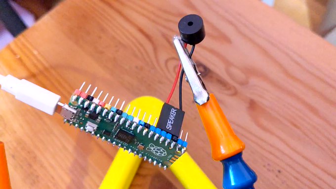
MIDI seems to be absurdly complex. In all the files I looked at, there didn’t seem to be much of a standard in encoding whether the note duration was in the NOTE_ON event or the NOTE_OFF event. Eventually, I managed to fudge a tiny single channel file that had acceptable note durations in the NOTE_OFF events. Here is the file:
# extremely crude MicroPython MIDI demo
# MicroPython / Raspberry Pi Pico - scruss, 2022-08
# see https://github.com/bixb922/umidiparser

import umidiparser
from time import sleep_us
from machine import Pin, PWM

# pin 26 - GP20; just the right distance from GND at pin 23
#  to use one of those PC beepers with the 4-pin headers
pwm = PWM(Pin(20))
led = Pin('LED', Pin.OUT)


def play_tone(freq, usec):
    # play RTTL/midi notes, also flash onboard LED
    # original idea thanks to
    #   https://github.com/dhylands/upy-rtttl
    print('freq = {:6.1f} usec = {:6.1f}'.format(freq, usec))
    if freq > 0:
        pwm.freq(int(freq))       # Set frequency
        pwm.duty_u16(32767)       # 50% duty cycle
    led.on()
    sleep_us(int(0.9 * usec))     # Play for a number of usec
    pwm.duty_u16(0)               # Stop playing for gap between notes
    led.off()
    sleep_us(int(0.1 * usec))     # Pause for a number of usec


# map MIDI notes (0-127) to frequencies. Note 69 is 440 Hz ('A4')
freqs = [440 * 2**((float(x) - 69) / 12) for x in range(128)]

for event in umidiparser.MidiFile("lg2.mid", reuse_event_object=True):
    if event.status == umidiparser.NOTE_OFF and event.channel == 0:
        play_tone(freqs[event.note], event.delta_us)
This isn’t be any means a general MIDI parser, but is rather specialized to play monophonic tunes on channel 0. The result is gloriously awful:
More Micropython programmers — and especially beginners — should know about Awesome MicroPython. It’s a community-curated list of remarkably decent MicroPython libraries, frameworks, software and resources. If you need to interface to a sensor, look there first.
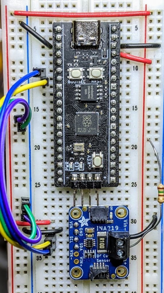
For example, take the INA219 High Side DC Current Sensor. It’s an I²C sensor able to measure up to 26 V, ±3.2 A. It does this by measuring the voltage across a 0.1 ohm precision shunt resistor with its built-in 12-bit ADC. I got a customer return from the store that was cosmetically damaged but still usable, so I thought I’d try it with the simplest module I could find in Awesome MicroPython and see how well it worked.
I guess I needed a test circuit too. Using all of what was immediately handy — a resistor I found on the bench and measured at 150.2 ohm — I came up with this barely useful circuit:
Should indicate a current of 3.3 / (150.2 + 0.1) = 21.96 mA
The INA219 would be happier with a much higher current to measure, but I didn’t have anything handy that could do that.
Looking in Awesome MicroPython’s Current section, I found robert-hh/INA219: INA219 Micropython driver. It doesn’t have much (okay, any) documentation, but it’s a very small module and the code is easy enough to follow. I put the ina219.py module file into the /lib folder of a WeAct Studio RP2040 board, and wrote the following code:
# INA219 demo - uses https://github.com/robert-hh/INA219

from machine import Pin, I2C
import ina219

i = I2C(0, scl=Pin(5), sda=Pin(4))
print("I2C Bus Scan: ", i.scan(), "\n")

sensor = ina219.INA219(i)
sensor.set_calibration_16V_400mA()

# my test circuit is 3V3 supply through 150.2 ohm resistor
r_1 = 150.2
r_s = 0.1  # shunt resistor on INA219 board

# current is returned in milliamps
print("Current       / mA: %8.3f" % (sensor.current))
# shunt_voltage is returned in volts
print("Shunt voltage / mV: %8.3f" % (sensor.shunt_voltage * 1000))
# estimate supply voltage from known resistance * sensed current
print("3V3 (sensed)  / mV: %8.3f" % ((r_1 + r_s) * sensor.current))
with everything wired up like this (Blue = SDA, Yellow = SCL):
all of the wires
Running it produced this:
I2C Bus Scan:  [64]

Current       / mA:   22.100
Shunt voltage / mV:    2.210
3V3 (sensed)  / mV: 3321.630
So it’s showing just over 22 mA: pretty close to what I calculated!
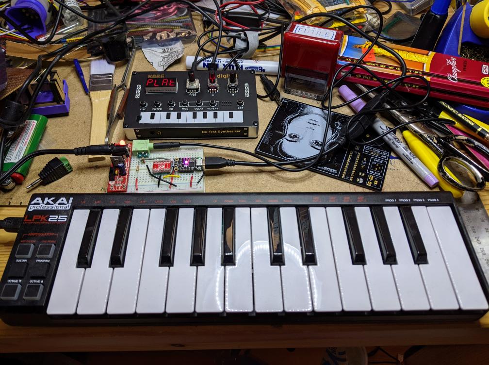
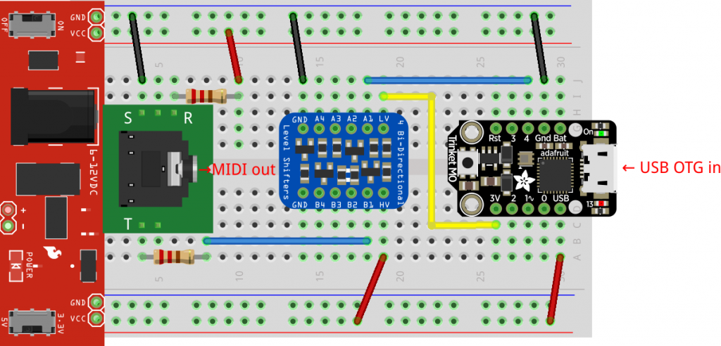
Akai LPK25 keyboard has USB MIDI out, but the Korg NTS-1 only has regular MIDI in. The little board in the middle acts as a USB host for the Akai and MIDI source for the Korg
“Just a test call. Time to stay home. Stay safe and stay home.”
This message from an unknown caller has sat on our landline answering machine since 2020 or 2021. No idea who or what sent it. All I know is it came in just before noon on a Tuesday morning. The entirely synthesized voice makes me think it’s a junk call, but there’s no scam attached. Just this message, slightly eerie, quite inexplicable.
In early 2013, I must’ve been left unsupervised for too long since I made The Quite Rubbish Clock:
It still isn’t human readable …
Written in (Owen Wilson voice) kind of an obsolete vernacular and running on hardware that’s now best described as “quaint”, it was still absurdly popular at the time. Raspberry Pis were still pretty new, and people were looking for different things to do with them.
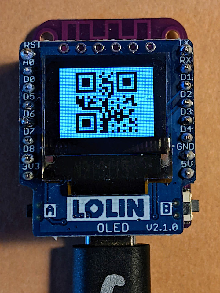
I happened across the JASchilz/uQR: QR Code Generator for MicroPython the other day, and remembered I had some tiny OLED screens that were about the same resolution as the old Nokia I’d used in 2013. I wondered: could I …?
OLED Shield on a LOLIN S2 Mini: very smol indeed
The board is a LOLIN S2 Mini with a OLED 0.66 Inch Shield on top, all running MicroPython. One limitation I found in the MicroPython QR library was that it was very picky about input formats, so it only displays the time as HHMMSS with no separators.
Source, of course:
# -*- coding: utf-8 -*-
# yes, the Quite Rubbish Clock rides again ...
# scruss, 2022-06-30
# MicroPython on Lolin S2 Mini with 64 x 48 OLED display
# uses uQR from https://github.com/JASchilz/uQR
# - which has problems detecting times with colons

from machine import Pin, I2C, RTC
import s2mini  # on Lolin ESP32-S2 Mini
import ssd1306
from uQR import QRCode

WIDTH = 64  # screen size
HEIGHT = 48
SIZE = 8  # text size
r = RTC()

# set up and clear screen
i2c = I2C(0, scl=Pin(s2mini.I2C_SCL), sda=Pin(s2mini.I2C_SDA))
oled = ssd1306.SSD1306_I2C(WIDTH, HEIGHT, i2c)
oled.fill(0)


def snazz():
    marquee = [
        "   **",
        "   **",
        "   **",
        "   **",
        "   **",
        "********",
        " ******",
        "  ****",
        "   **",
        " quite",
        "rubbish",
        " clock",
        "  mk.2",
        "<scruss>",
        " >2022<"
    ]
    for s in marquee:
        oled.scroll(0, -SIZE)  # scroll up one text line
        oled.fill_rect(0, HEIGHT-SIZE, WIDTH,
                       SIZE, 0)  # blank last line
        oled.text("%-8s" % s, 0, HEIGHT-SIZE)  # write text
        oled.show()
        time.sleep(0.25)
    time.sleep(5)
    oled.fill(1)
    oled.show()


snazz()  # tedious crowd-pleasing intro

qr = QRCode()
while True:
    qr.add_data("%02d%02d%02d" % r.datetime()[4:7])
    qr.border = 1  # default border too big to fit small screen
    m = qr.get_matrix()
    oled.fill(1)
    for y in range(len(m)):
        for x in range(len(m[0])):
            # plot a double-sized QR code, centred, inverted
            oled.fill_rect(9 + 2*x, 1 + 2*y, 2, 2, not m[y][x])
    oled.show()
    time.sleep(0.05)
    qr.clear()
If your output is glitchy, you might need to put the following in boot.py:
import machine
machine.freq(240000000)
This increases the ESP32-S2’s frequency from 160 to 240 MHz.
Update: there’s a fork of uQR that provides better character support, particularly those required for sending Wi-Fi Network config.
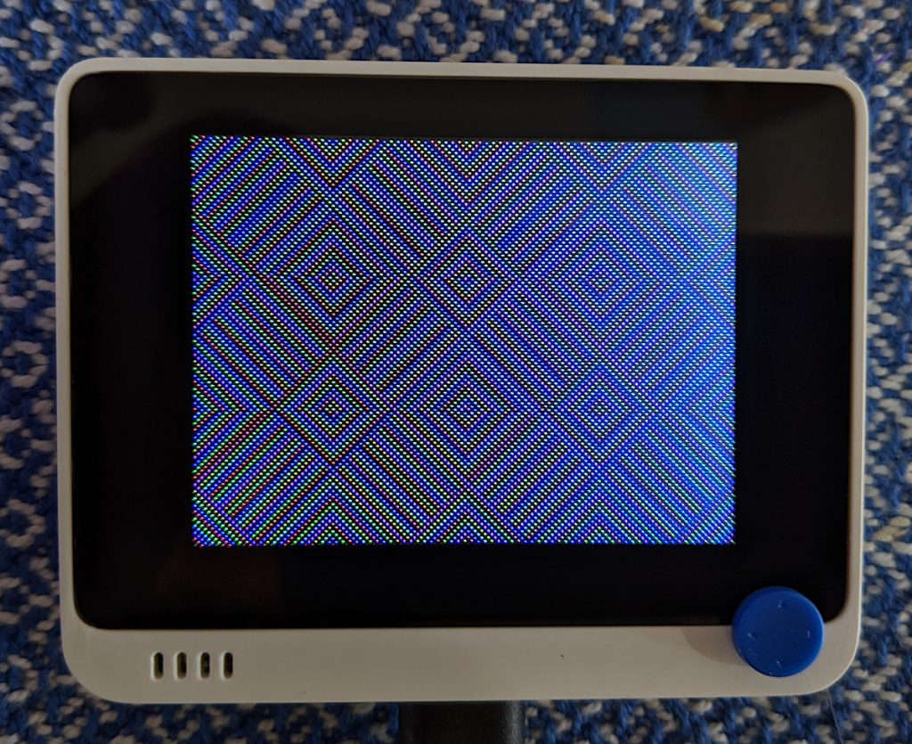
recreated from the Threlkeld Granite Co Ltd’s Album: Ornamental Granitic Tiles (1898), sheet 8
The Internet Archive has Threlkeld Granite Co Ltd’s Album of ornamental granitic tiles online, and I’m really digging the patterns of the hydraulic tiles they made. I’ve recreated some of their patterns in InkScape, and made this small demo by tiling bitmapped renderings.
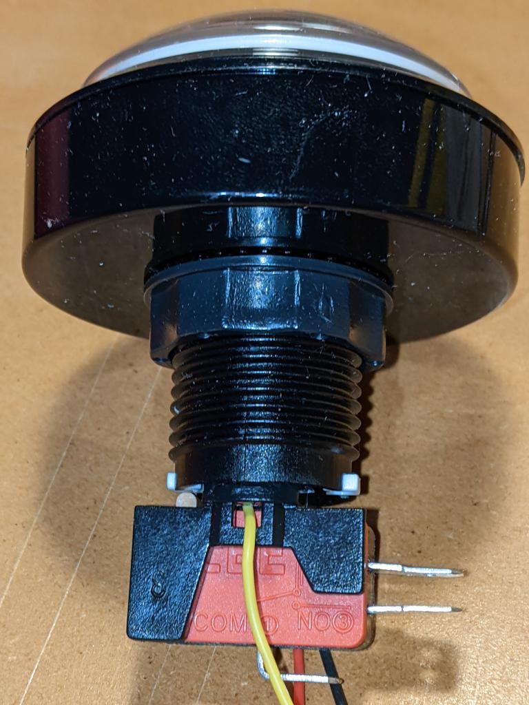
Somewhat painterly view of the button doing its thing. The weird clunking sound is my camera’s continuous focus. For a clearer but more flickery view, see here
Following on from a customer query at Elmwood Electronics, I can confirm that one can install install addressable RGB LEDs/NeoPixels inside one of these large buttons. It’s not the easiest build, so whether one should attempt this is another matter entirely.
Thin (and I mean thin: I used 28 AWG) Silicone Cover Stranded-Core Wire in several colours. You’ll want to cut this quite long at first, as you have to ease it through some tiny holes in the button assembly. If you solder connectors on the end, you won’t be able to disassemble or install the button without cutting them off. Do I speak from experience here? You betcha!
The usual soldering/hot gluing/bending/prying/grabbing/cutting tools you already know and love. In addition, you might consider a non-marring spudger and a pair of small(ish) arterial forceps (aka hemostats, aka Kelly forceps, aka fishing hook removal pliers)
I’m not going to cover soldering the wires to the LED PCB in any depth here. You’ll need three wires: 5 V power, Ground and Data. Even though the LEDs I used need 5 V power, they are quite happy with 3.3 V logic on the data line. They need more than 3.3 V power to light, though.
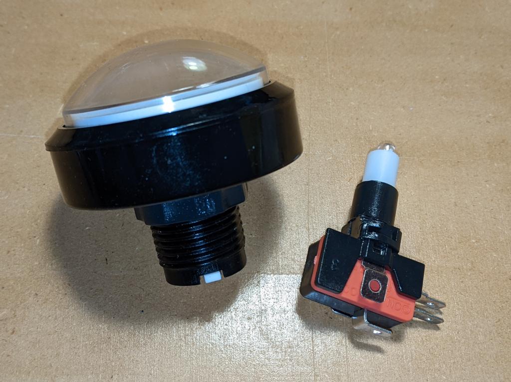
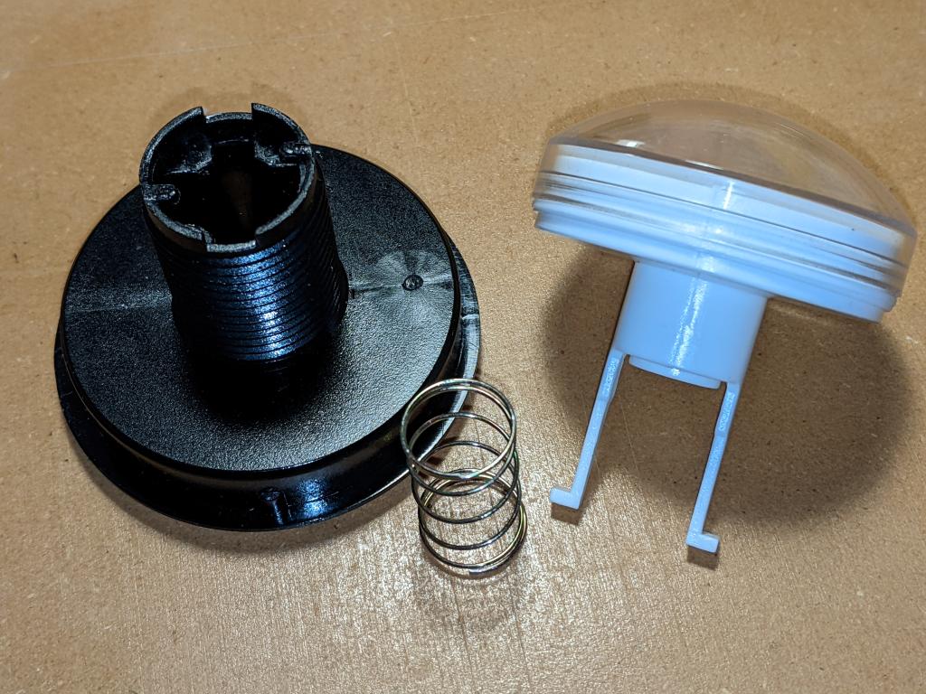
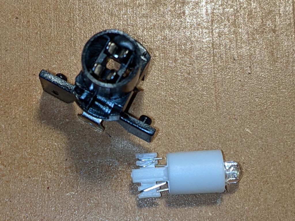
The button in two pieces, as you might expect to receive it
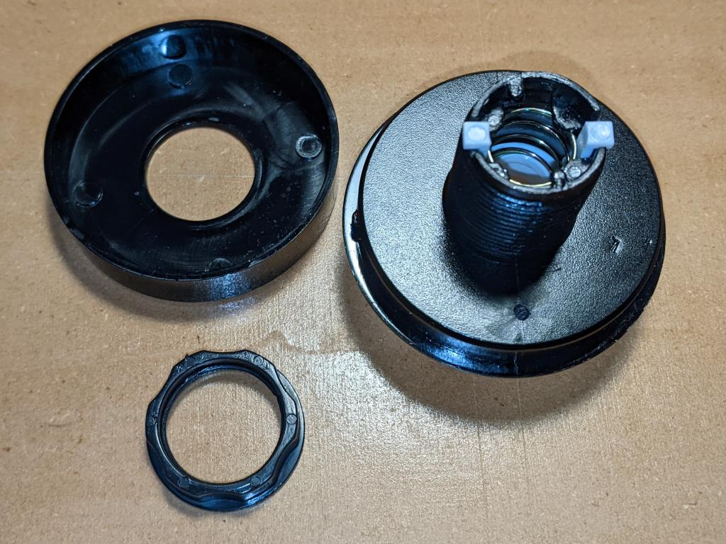
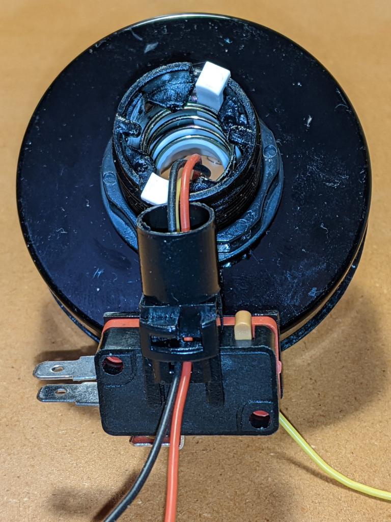
Main parts of the button top, once you’ve removed the lock ring
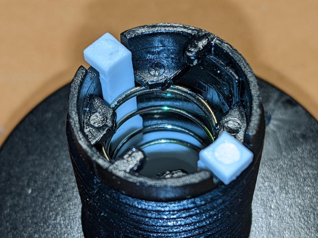
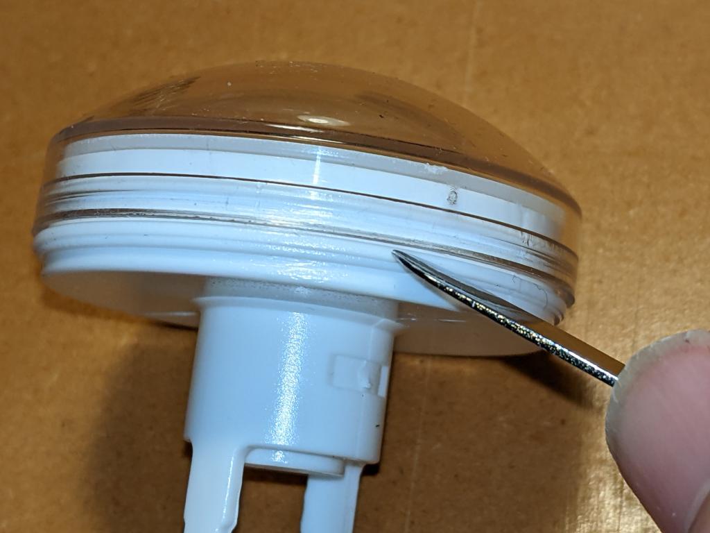
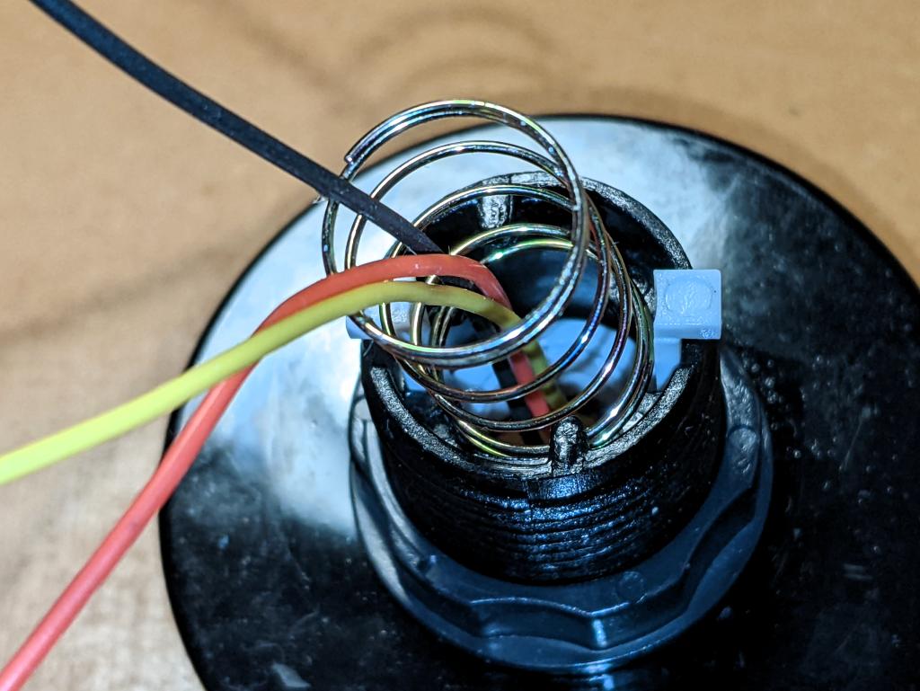
First step is to ease the spring out without bending it too much or breaking the retainer tabs
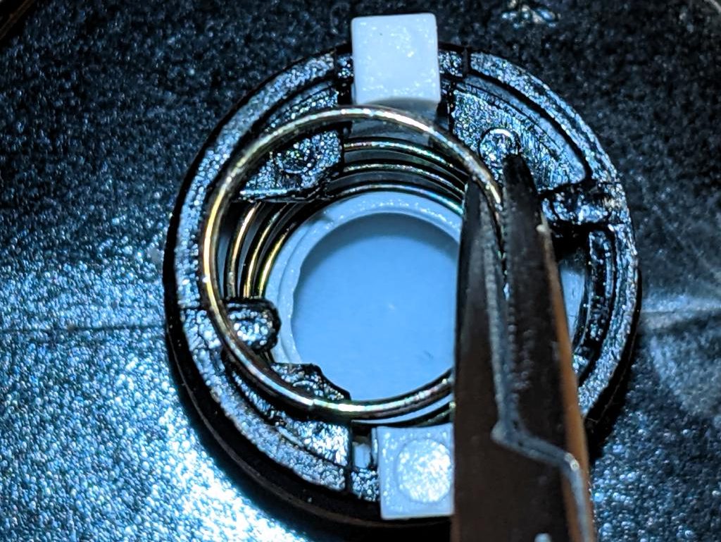
I used small forceps to ease the spring out. Once you get it started, it unscrews easily from behind the retainers
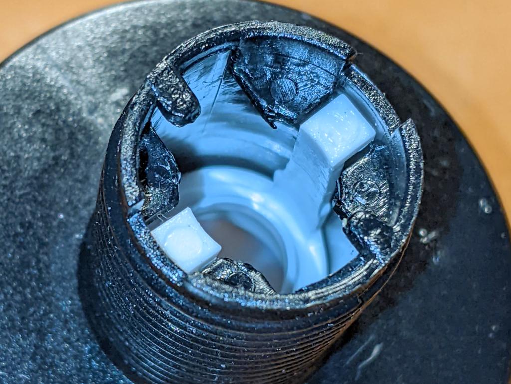
Now the spring is out the way, you can squeeze in the actuator tabs and push them down the shaft to liberate the button top
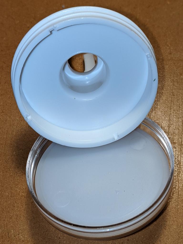
The button top disassembled
Carefully lever off the clear top with a blunt tool like a spudger. Now would have been a great time to clean dust and other wee bits off your workspace, as they’ll surely end up inside the button, looking nasty
The button top opened up. The cavity is about 45 mm in diameter and only a few millimetres deep
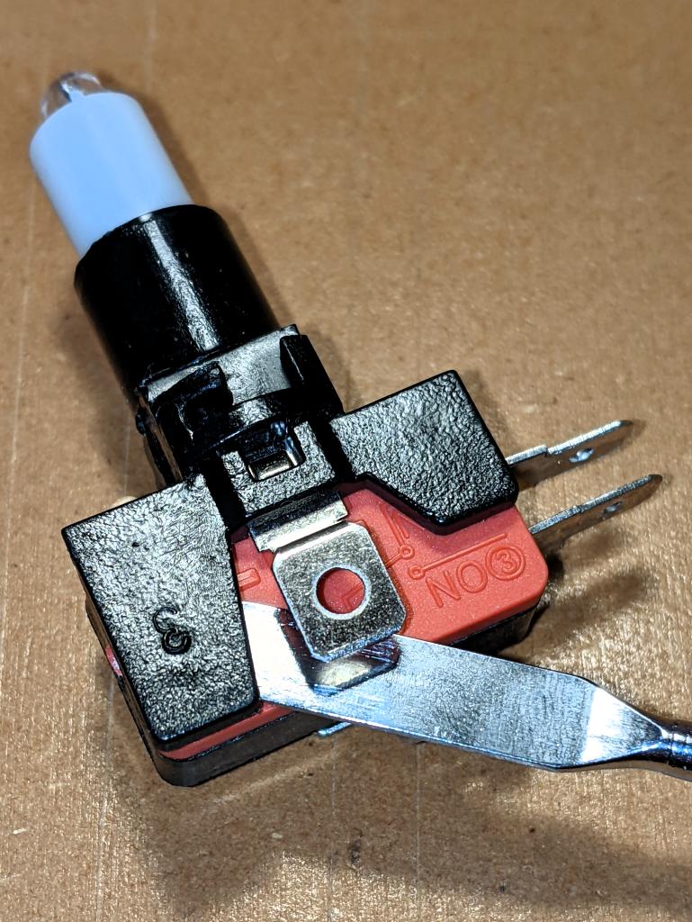
Removing the LED holder from the microswitch is done by levering open (gently) the plastic tab that clamps the holder onto the switch.
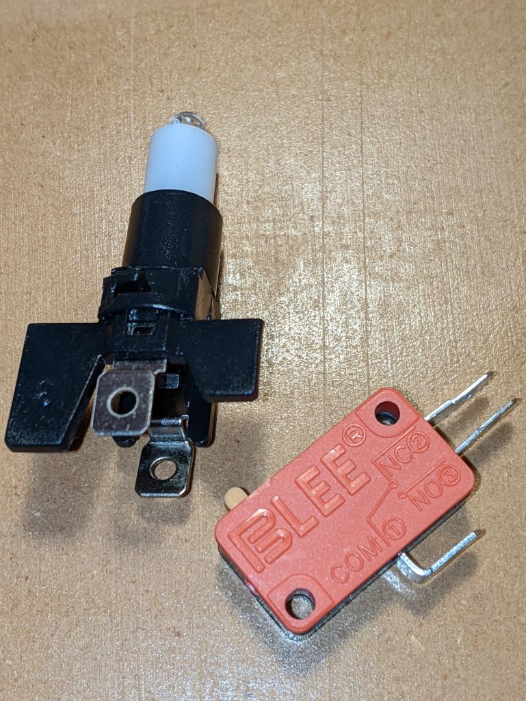
LED holder and microswitch separated. For normal button operation, the contacts NO and COM become connected when the button is pressed. The spade contacts on the LED holder look like they should come out, and they will (soon)
Pull the LED out from the holder, and you’ll see the metal clips that held it in place. These clips have to come out: I found the pushing them in slightly while pulling down on the spade connector eased them out eventually
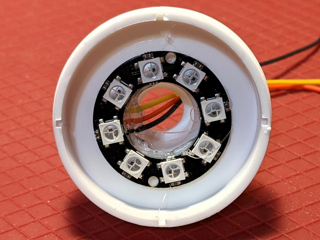
LED ring hot glued into place. Make sure that the wires are properly secured, as you don’t want to take this apart againFit the clear button top back inside the base, feeding the wires through the shaft. Fitting the return spring back in is a bit more chaotic than getting it out. I ended up jamming it in with forceps, and it seemed to sort out okay despite that
The really fiddly bit: feeding the wires through the tiny gaps where the LED holder clips/contacts used to be. Even using thin (28 AWG) silicone covered wire, all three wires couldn’t fit down one side. Make sure the wires are pulled gently through, and aren’t snagged anywhere
Finished! Make sure that the switch actuates properly by lining up the LED holder in the bayonets inside the shaft. Of course, you’ll have wanted to install the button in your project before doing this assembly, as you’ll have to feed those pesky wires back through again if you haven’t …
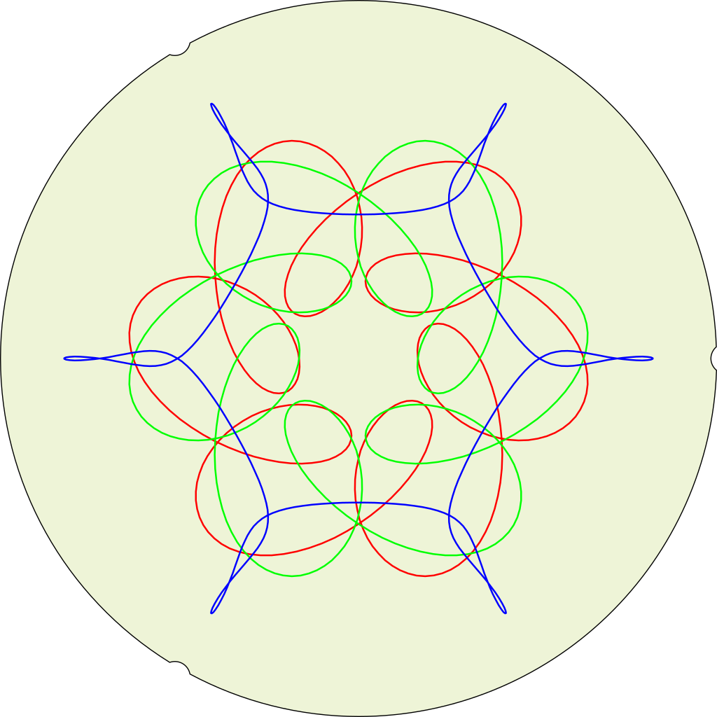
This is what I simulated earlier – except drawn on a real Magic Designer. Something’s off with what I modelled …
All of these are drawn with the Magic Designer angle set to 57, which puts the crank discs exactly in phase. The blue circle in the middle is an exactly image of a crank disc, if perhaps a very dull plot.
I even emulated the locating notches at the edge of the paper …
Simulated (and not quite right yet) output from a “HOOT-NANNY” or Magic Designer, a proto-Spirograph toy that drew six-sided curves on round paper sheets. It was made by Howard B. Jones and Co. of Chicago, IL and first sold in 1929. The company’s better known for producing Jones Plugs and Sockets, sometimes known as Cinch-Jones connectors. The “HOOT-NANNY” name was dropped when production moved to the Northern Signal Company of Saukville, WI.
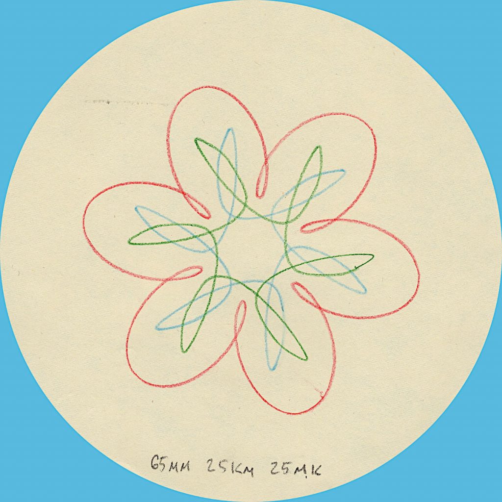
My eBay-acquired Magic Designer is quite beaten up, and doesn’t always produce accurate results. Here’s how one should look, from the instruction pamphlet:
I can’t shake the feeling this was originally something like an artillery ranging tool or suchlike
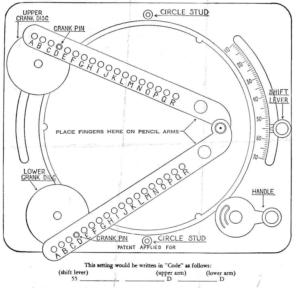
As far as I’ve been able to work out, the parameters of the machine are:
central turntable is 6″ in diameter, with 192 gear teeth around the edge;
each crank disc is 1″ diameter (32 teeth), with the crank pin at 3/8″ radius;
the shift lever has a 10-70 degree scale, which corresponds to moving the upper crank disc between 30-90 degrees of arc from the lower (fixed) crank disc;
the pencil arms have 18 holes labelled A to R, at 1/4″ spacing from 5.75 to 1.5″. The perpendicular distance from the pivot holes to the pencil is 5/16″. This small offset makes very little difference to the overall arm length.
If we model the toy with a fixed turntable:
the crank pins describe epitrochoids around the edge of the paper;
the pencil point traces the intersection of two circles of radius the lengths of the pencil arms, each centred on a crank pin.
The biggest thing that tripped me up was that PicoMite BASIC starts arrays at 0. OPTION BASE 1 fixes that oversight. It would have been nice to have OpenProcessing’s HSV colour space, and an editor that could handle lines longer than 80 characters that didn’t threaten to bomb out if you hit the End key, but it’ll serve.
Source below:
' autumn in canada
' scruss, 2021-11
' a take on my https://openprocessing.org/sketch/995420 for picomite
OPTION base 1
RANDOMIZE TIMER
' *** initialize polar coords of leaf polygon and colour array
DIM leaf_rad(24), leaf_ang(24), px%(24), py%(24)
FOR i=1 TO 24
READ leaf_rad(i)
NEXT i
FOR i=1 TO 24
READ x
leaf_ang(i)=RAD(x)
NEXT i
DIM integer c%(8)
FOR i=1 TO 8
READ r%, g%, b%
c%(i)=RGB(r%,g%,b%)
NEXT i
' *** set up some limits
min_scale%=INT(MIN(MM.HRES, MM.VRES)/8)
max_scale%=INT(MIN(MM.HRES, MM.VRES)/6)
min_angle=-30
max_angle=30
min_x%=min_scale%
min_y%=min_x%
max_x%=MM.HRES - min_x%
max_y%=MM.VRES - min_y%
CLS
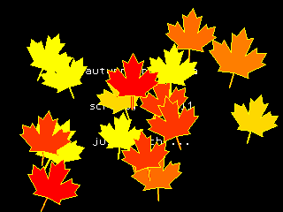
TEXT MM.HRES/2, INT(MM.VRES/3), "autumn in canada", "CM"
TEXT MM.HRES/2, INT(MM.VRES/2), "scruss, 2021-11", "CM"
TEXT MM.HRES/2, INT(2*MM.VRES/3), "just watch ...", "CM"
kt%=0
DO
cx% = min_x% + INT(RND * (max_x% - min_x%))
cy% = min_y% + INT(RND * (max_y% - min_y%))
angle = min_angle + RND * (max_angle - min_angle)
sc% = min_scale% + INT(RND * (max_scale% - min_scale%))
col% = 1 + INT(RND * 7)
leaf cx%, cy%, sc%, angle, c%(7), c%(col%)
kt% = kt% + 1
LOOP UNTIL kt% >= 1024
END
SUB leaf x%, y%, scale%, angle, outline%, fill%
FOR i=1 TO 24
px%(i) = INT(x% + scale% * leaf_rad(i) * COS(RAD(angle)+leaf_ang(i)))
py%(i) = INT(y% - scale% * leaf_rad(i) * SIN(RAD(angle)+leaf_ang(i)))
NEXT i
POLYGON 24, px%(), py%(), outline%, fill%
END SUB
' radii
DATA 0.536, 0.744, 0.608, 0.850, 0.719
DATA 0.836, 0.565, 0.589, 0.211, 0.660, 0.515
DATA 0.801, 0.515, 0.660, 0.211, 0.589, 0.565
DATA 0.836, 0.719, 0.850, 0.608, 0.744, 0.536, 1.000
' angles
DATA 270.000, 307.249, 312.110, 353.267, 356.540
DATA 16.530, 18.774, 33.215, 3.497, 60.659, 72.514
DATA 90.000, 107.486, 119.341, 176.503, 146.785, 161.226
DATA 163.470, 183.460, 186.733, 227.890, 232.751, 270.000, 270.000
' leaf colours
DATA 255,0,0, 255,36,0, 255,72,0, 255,109,0
DATA 255,145,0, 255,182,0, 255,218,0, 255,255,0
You could probably use AUTOSAVE and paste the text into the PicoMite REPL. I used an ILI9341 SPI TFT LCD Touch Panel with my Raspberry Pi Pico along with some rather messy breadboard wiring.
Fun fact: the maple leaf polygon points are derived from the official definition of the flag of Canada.