I’ve found that OpenSCAD is really good for producing 2d designs in a very small amount of code. Here are three examples to play with:
Diagonal Section through Menger sponge (SVG) (OpenSCAD source) — this may take a while to render, as it’s making a Menger sponge in 3D and then slicing through it to make the projection.
(If you take out the projection() clause, it looks like this in 3D:
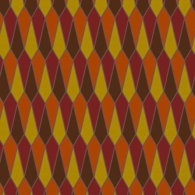
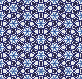
fell out of an arch design I was studying, and I thought it was too nice to throw away. Must’ve been something about the falling leaves that made me choose colours like these.
svgo is, on the face of it, pretty neat: it takes those huge vector graphic files and squozes them down to something more acceptable. Unfortunately, though, the authors have seen too many files with junk machine-generated <metadata> sections, and decided that it’s all worthless.
Metadata isn’t junk; it’s provenance. Your RDF? Gone. Your diligently researched and carefully crafted Dublin Core entries? Blown away. The licence you agonized over? teh g0ne, man. svgo does this by default. It would be very easy to use this tool to take someone else’s graphic, strip out the ownership information, and claim it as your own. It would be wrong to do that, but the original creator would have to find your rip-off and go to the effort of challenging your use of it. All so much work, all so easily avoided.
You can make svgo do the right thing by calling it this way:
There’s apparently a config option to make this permanent, but the combination of javascript, no docs and YAML brings me out in hives. Given that the metadata section of a complex file is typically a couple of percent of the total, it’s worth keeping. Software passes; but data lives forever, so be kind to it.
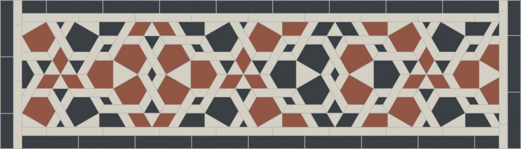
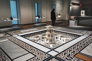
You might have noticed that I’ve become a bit obsessed with Arabic/Islamic geometric designs lately. Clues include posts like this, this, also this, and maybe even this. When I refer to Islamic Geometric Design, I’m more talking about the frameworks, repeat units or grids that are the starting point for the intricate and hypnotic abstract designs that have traditionally been used in Islamic architecture for over a thousand years. Here’s an example of the larger patterns in context:
I’ve been following Eric Broug‘s methods of construction that use a ruler and compass exclusively. Not being that great with manual dexterity, I’ve found these much slower to draw than I could on a computer. Consequently, I looked around for a good, free tool that people could use to start making these drawings. Most of the operations (including drawing from one intersection to another, rotating objects around a point, buffering lines into polygons) can be done by CAD packages, but these often have a steep learning curve. CAD packages also don’t tend to have many artistic functions.
Thankfully, the free drawing packing Inkscape has almost all of the features I need. Just one of the features I use quite often (creating a circle from a centre point and a point on the circumference; in other words, emulating a compass) isn’t built in, but can be done with a simple sequence of operations. In this article, I hope to show you some techniques you can build on for making your own patterns.
Installing Inkscape
This is covered well on the Inkscape website, so I won’t repeat it here. It’s important to get the most recent stable version of Inkscape. Some Linux distributions provide a really old version, so make sure you’re using at least version 0.91.
Inkscape runs on Linux, Mac and Windows. On Mac, it’s a little slow and uses some non-(Mac-)standard keyboard shortcuts. You may also have to install XQuartz on your Mac for it to run. It works fine on Windows (I tested 8.1).
Snapping is your friend
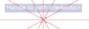
You’re going to have to get to know and love the Snapping Toolbar, shown at right. When you enable snapping, the items you draw or modify are locked to the node, intersection, object centre or grid point nearest to your cursor. When snapping is active, you get a little hovering info box showing you what Inkscape thinks you want to snap to:
I’ve enlarged the screen grab so you can make the info box out more clearly.
Snapping allows you to place lines in geometrically precise locations if you work up a drawing from a template or construction lines. All of the templates I made have the most useful snapping modes enabled:
Snap to Intersection — prefer where lines cross
Snap to Cusp Node —prefer end points of lines, or local extrema of polygons
Snap to Object Centre —prefer the centre of objects.
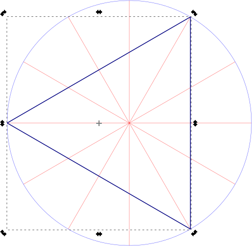
Triangle from intersections (source SVG is linked from image)
Here’s a simple example of a triangle drawn from construction lines. I couldn’t ever draw a perfect equilateral triangle freehand, but with snapping, it’s four clicks (three vertices, then a final click on the first vertex to close the figure), and it’s done perfectly.
Incidentally, most of the patterns I make use straight lines. In Inkscape, you’ll want to use the Pen tool () with straight lines enabled ().
Moving the Centre of Rotation
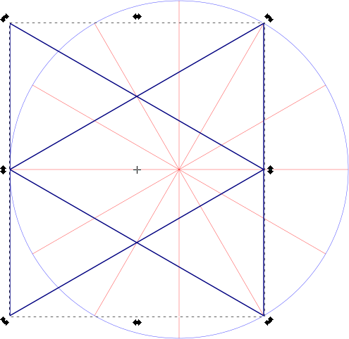
When you double-click an object in Inkscape in Select & Transform mode (), you get shown the rotation handles and the all-important Centre of Rotation. By default, the centre of rotation is in the centre of the bounding box of the object; that is, the centre of the smallest horizontal box that encloses the object. Here it’s marked by a small cross:
Let’s say we want to make a six-pointed star from this triangle. You might think that if you duplicated it (keyboard shortcut: Ctrl+D) and flipped it horizontally (keyboard shortcut: h), you’d get your star. Alas, no star for you:
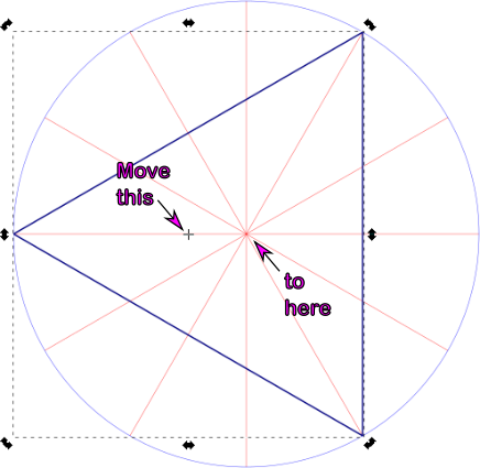
What we wanted to do was to flip the triangle around the centre of rotation of the radial construction lines, and to do that we need to drag the triangle’s centre of rotation over to the centre of the construction lines:
You’ll know when you’ve got it in the right place, as Inkscape’s snapping info box should tell you:
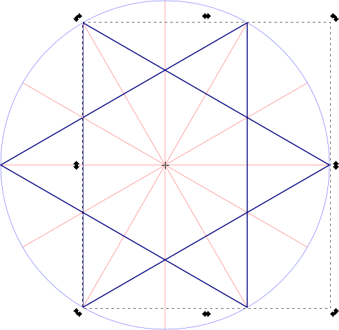
Let’s try that duplication and flipping thing again:
Moving the centre of rotation makes all the difference.
Rotation & Duplication
Now that we can move the centre of rotation, we can use that to build up compound objects:
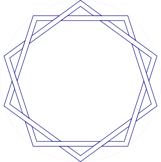
This interleaved set of strapwork pentagons is made from 10 segments:
Segment for interleaved pentagons (source SVG is linked from image)
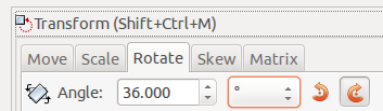
Since there are 10 segments, we have to rotate each segment 36° (= 360°/10) to fill up the whole circle. For this, we use the Transform tool’s Rotate tab:
If you’re wanting to avoid doing even division in your artwork, here’s a table for many common values:
Number of Segments
Rotation / °
2
180
3
120
4
90
5
72
6
60
8
45
10
36
12
30
16
22.5
18
20
20
18
24
15
36
10
Applying nine duplicate-rotate steps, we get this result:
Stroke to Path
(work in progress …)
Simple fine lines (SVG source linked from image)
Most geometric figures have lines with some thickness to them. Guide lines alone are pretty boring.
You can use Object → Fill & Stroke and set Stroke Style on a path to make it wider, but sometimes you might want to work with the intersections of the edges of these paths. Fortunately, Inkscape makes this relatively easy.
First, give your path the width you want, say 3-5 mm. Then, with the path selected, use Path → Stroke to Path. At first, nothing appears to have happen, but change the Fill to none (the ‘×’ icon) and the Stroke Paint to solid. Suddenly, the path will appear to get really thick, but reduce the Stroke Style: Width down to a fine line, and you’ll end up with the outline of your original path.
Stroke to path, and partially filled (SVG source linked from image)
I’ve jumped ahead a bit with the illustration, and started to fill in the strapwork. Inkscape will snap to the nodes on the edges of your figure, and you can decorate it any way you wish.
(The Stroke Style: Join and Stroke Style: Cap permanently affect the outline path. You’ll get quite good at using Undo until you get the effects you want. Really pointy shapes will need a custom Stroke Style: Mitre Limit, as graphics programs try to limit really acute intersections, as they can get awkwardly long and trail off the page.)
A gratuitously pointy star that needed a custom mitre limit (SVG source linked from image)
Other useful techniques
Separating construction lines from drawing objects by using Layers is very helpful. Once you hide the construction lines, your patterns look much more impressive, as you can’t easily see how it was put together.
The Select Same command allows you to select objects with the same fill and/or stroke style. I find this useful for selecting objects for grouping, or moving to other layers.
Clipping objects to basic tile shapes can help to make seamless repeat units for tiling.
The Clone → Create Tiled Clones … command is immensely powerful for making patterns out of repeat units. It’s also rather hard to use. I hope to add some basic examples later, though it’s hard to get this exactly seamless. This tutorial helps for a limited number of cases.
These SVG templates are modelled after Eric Broug‘s drawing templates for Islamic Geometric Design pattern elements. Although written for Inkscape, they should be usable with almost any graphics program.
By enabling snapping to nodes and object centres, your drawing program can act like an accurate straight edge and compass for constructing geometric figures.
File Nomenclature
The files are name N-LL-S.svg, where:
N — is the root symmetry: 4-fold, 5-fold, 6-fold, etc.
LL — the total number of lines arranged evenly around the circle. This will always be a multiple of N.
S — If the total number of lines has another symmetry that is a factor, this is S. If S = 0, then only the root symmetry is marked.
Examples:
4-12-6.svg — base symmetry 4-fold (square/diamond), with 12 lines or 30° spacing. Hexagonal (6-fold) guidelines are highlighted in a different colour.
5-10-0.svg — base symmetry 5-fold (pentagonal), with 10 lines or 36° spacing. No other guidelines are highlighted.
Features
In Inkscape 0.91:
units set to mm
snapping set to cusp nodes, intersections, and object rotation centres
construction lines on a separate layer (‘construction’) from the active layer (‘drawing’)
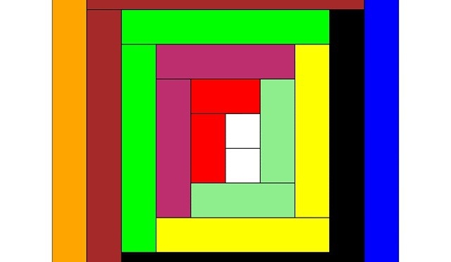
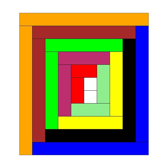
Rods! Or more specifically, Cuisenaire® Rods! Staples of my childhood arithmetic education: coloured wooden rods (now plastic, which will save them from the mouldy fate that befell some sets at Mearns Primary School), 1 × 1 × 1–10 centimetres long. Use them for counting, number lines, don’t-do-that renditions of Sun Arise, but absolutely never for flinging at tiny classmates.
Since it may actually have been Mrs. Cuisenaire who came up with the concept of rods, I drew a log cabin quilt section in virtual rods. The Gattegno in the title refers to Caleb Gattegno, the mid-century educator who popularized Cuisenaire’s work.
Should you too feel the need to have a virtual set of rods, here are some files you can play with in Inkscape (or any other SVG-aware editor):
rods.svg — A palette of horizontal and vertical rodsrods-quilt.svg – source for the header image
The colours might be a bit off reality, but they’re near enough. I found it helpful to set a grid snap in Inkscape to 1 cm so that you could get the rods to align easily. If you want to get really nerdy, here’s the PostScript source I used to create the rods: rods.ps. I think I finally got the hang of basic arrays in PostScript …
Creating this was in noway a means of me displacing getting round to doing my taxes this year, nosirree.
If you want to work out how tall a wind turbine is at a distance, you can use simple proportion:
If I hold my thumb at arm’s length, it’s about a metre from my eye. The tallest a turbine would appear from shore would be equivalent to the height of the top joint of my thumb. That’s pretty small.
I’ve updated the markup for Augustus Carp, Esq: by Himself, and now host a local copy. Apart from changing the TeX-style quotes to proper Unicode typographic one, the main change has been converting the images to SVG for added crispness.
set terminal svg size 400,400
 set output "fig-spiro11.svg"
 set size ratio -1
 set nokey
 set noxtics
 set noytics
 set noborder
 set parametric
#
 x(t)=(R-r)*cos(t) + p*cos((R-r)*t/r)
 y(t)=(R-r)*sin(t) - p*sin((R-r)*t/r)
#
 R=100.0; r=-37.0; p=50.0
 set samples 8001
#
 plot [t=0:320*pi] x(t),y(t)
Even to upload an SVG file, I have to bypass WordPress’s built in whitelist using PJW Mime Config, and manually add support for image/svg+xml. Otherwise, it’s refused as an insecure file. (All my files are quite well adjusted, I’ll have you know.)
Say if I want to embed this SVG image. I’d probably want to do something like:
Yay, that sorta works – but it doesn’t scale the image. You know what the S in SVG stands for? That’s right – Scalable. Doesn’t seem to allow scaling. Kinda defeats the purpose, doesn’t it?
I saw this on an envelope the other day. What can it mean?
To me, it clearly means “May be inspected only by two-dimensional officials with the Eye of Horus wearing a cap at 30° bearing insignia of an upturned army helmet with a lion rampant and a blancmange.”
Oh, and this is my first post with SVG graphics. Yay!
 Diagonal Section through Menger sponge (SVG) (OpenSCAD source) — this may take a while to render, as it’s making a Menger sponge in 3D and then slicing through it to make the projection.
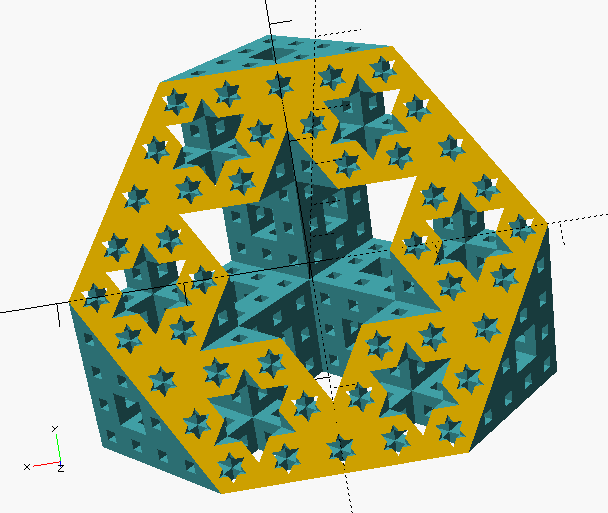 )
) Pattern from Ak Medrese, Nigde, Turkey (SVG) (OpenSCAD source) — design after a construction by Eric Broug.
 Basis of a pattern from the Alhambra (SVG) (OpenSCAD source)
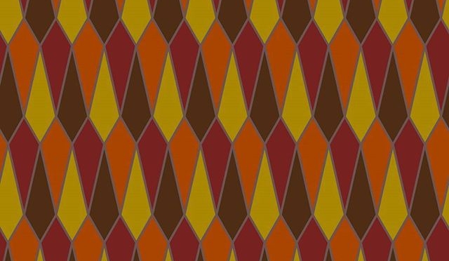


