Beavers are usually quite wary of me down at Bluffer’s Park, but I was about three metres away from this one and I didn’t seem to be interrupting.
A beaver in Bluffer’s Park gathers an unhurried snack of tasty green fronds
The original video is nearly half a gigabyte. I don’t really want to use YouTube, so you’re getting it at 360p, courtesy of ffmpeg and lots of swearing.
I don’t want to turn this post into a rant about ffmpeg and its very special options, so here, for posterity, are the command lines I used to generate this from a Pixel 8 phone video:
this image is supposed to be made almost entirely of sextant blocks, the Unicode characters around U+1FB00 – U+1FB1E made out of two columns of three blocks. They’re originally from broadcast teletext, and were made to build low-resolution images on a text screen
Making the pixel to character map is quite tricky. The Sextant character block isn’t contiguous, and it’s not in the order we need. It’s also missing four characters: empty block, full block, left half block and right half block. These have to be pulled in from other Unicode blocks.
This is the map I came up with, from 0–63 with LSB at bottom right and MSB at top left:
Hey! This code situation may be changing soon, but this article was written about MicroPython v1.25.0 on RP2040. The situation on the Raspberry Pi Pico W / 2W /RP2350 might be quite different.
Many micro-controllers have timed energy-saving modes you can engage when they are idle. These are typically one of:
light sleep: where memory contents are retained, but some parts of the CPU and peripherals are turned off to reduce current;
deep sleep: memory is cleared, most of the CPU and peripherals are powered off. The CPU will reset fully on restart, so your program has to reload.
While MicroPython on the RP2040 has both machine.lightsleep() and machine.deepsleep() functions, there’s not much difference between them. In fact, the deepsleep() routine is merely lightsleep() followed by reset(). So there isn’t any efficiency gain in using deepsleep over lightsleep.
The functions take one argument: the sleep time, given in milliseconds. The largest value that is accepted is 4294966, or (2**32 // 10**3) - 1. That’s 71′ 34″. If you give a larger number, this exception is thrown: ValueError: sleep too long, and the function returns immediately.
If you’ve used machine.deepsleep(), you might want to know whether your micro-controller was started by applying power, or started from the reset() after deepsleep(). The machine.reset_cause() function returns one of two values:
machine.PWRON_RESET: if the CPU was started from power on, or by briefly grounding the RUN pin;
machine.WDT_RESET: if the CPU was soft reset, either by a watchdog timer or other software reset. This is the state returned after deepsleep().
Other MicroPython ports have more nuanced ways of handling sleep and reset states with better power saving.
If you’re running a tight polling loop and still wish to save a little power, machine.idle() is the recommended method.
If you have a Wemos/LOLIN S3 MINI PRO board, you might find that firmware images don’t flash so well. That’s because the ESP32-S3FH4R2 has 4 MB of flash storage, and most ESP32-S3 boards have 8 MB.
This trims down a standard MicroPython ESP32-S3 firmware from a 4 MB filesystem partition down to 2 MB, and sets the overall flash size to 4 MB. Upload that to your board, and all will be well.
Alternatively, v1.26 supports “4MiB and larger” flash chips. I have confirmed that ESP32_GENERIC_S3-20250724-v1.26.0-preview.bin works as expected:
$ mpremote a1 run boardstats.py
Board       : Generic ESP32S3 module with ESP32S3
Frequency   : 160 MHz
Free Memory : 2061232
File storage: 2036 / 2048 K
Just before the Extinction, goth teen dinosaurs would lie on the ground and writhe into contorted positions. They were neither sure why they did this, nor why they called it “Fossil Practice”.
That Brother laser printer you bought can also pretend it’s a plotter. One of the requirements embedded in a PCL-compatible printer is an implementation of HP-GL/2. This is a slightly modified version of the page description language used by HP’s pen plotters. With care, you can make proofs on a laser printer.
But add some magic header bytes (0x1b, 0x45, 0x1b, 0x25, 0x30, 0x42) and some trailer bytes (0x1b, 0x25, 0x30, 0x41, 0x1b, 0x45), and your printer understands it’s a PCL file.
The file, complete with header and trailer, is here:
full page scan of that HP-GL file as printed on a Brother MFC-L2750DW
HP-GL/2, on mono lasers at least, has some differences to the version used on plotters. The biggest difference is that there’s just one pen. You can change the pattern and line attributes of this pen, but you don’t get to change to multiple pens with different colours.
In late 2024, SparkFun Electronics relaunched their website. In doing so, they deleted roughly 20 years of archived product information, along with all associated datasheets, schematics and tutorials. Luckily, the Internet Archive’s Wayback Machine has good records of the site, and I was able to recover links to 5934 deleted products.
Martin Raynsford / Solarbotics Solar Marble Machine loving glare off deep snow
Still going strong after more than a decade in the front window, the Solar Marble Machine has been running flat out all day because of the glare from the deep snow outside. It might normally do one click a day, if any at all.
Yes, I was very surprised that the DevEBox STM32H7 at 400 MHz was faster than the 500 MHz MIMXRT1011 in the Metro M7. What was even more impressive is that the STM32H7 board was doing all the calculations in double precision, while all the others were working in single.
As for the other boards, the ESP32 variants performed solidly, but the ESP8266 in last place should be retired. The Raspberry Pi Pico 2 W was fairly nippy, but the original Raspberry Pi Pico is still a lowly Cortex-M0+, no matter how fast you clock it. The STM32F4 boards were slower than I expected them to be, frankly. And yay! to the plucky little W600: it comes in second last, but it’s the cheapest thing out there.
All of these benchmarks were made with the same code, but with two lines changed:
The I2C specification, which is a minor syntax change for each board;
The input trigger pin. Some boards like these as numbers, some take them as strings. Pro tip for W600 users: don’t use D0 for an input that’s tied to ground, unless you want the board to go into bootloader mode …
I’d hoped to run these tests on the SAMD21 little micro-controllers (typically 48 MHz Cortex-M0), but they don’t have enough memory for MicroPython’s framebuf module, so it’s omitted from the build. They would likely have been very slow, though.
In the spirit of fairness, I also benchmarked CircuitPython on a Arduino Nano RP2040 Connect, which has the same processor as a Raspberry Pi Pico:
So it’s about 10% quicker than MicroPython, but I had to muck around for ages fighting with CircuitPython’s all-over-the-shop documentation and ninny syntax changes. For those that like that sort of thing, I guess that’s the sort of thing they like.
Yeah, it’s pretty neat to be able to do that on a Commodore VIC-20 with 5K of RAM. But how about a ZX81 with only 1K? With screen memory that moves around depending on how much stuff you have on the screen? No problem:
that’s it: that’s the whole program
The tricky part is printing just enough to the screen that you have enough memory to store the array and still have enough memory for your program. I did that by printing four lines of “🮐” characters (CHR$ 136 on the ZX81, U+1FB90) and moving the cursor down just far enough that later output wouldn’t zap my data. The screen address (given by the D_FILE pointer at 16396) is used as an array of 100 characters.
The ZX81’s (non-ASCII) character set has a nice quirk that Space is CHR$ 0, and inverse video Space (“█”) is at CHR$ 128. So you can use NOT to toggle the value.
Here’s the program listing, with Unicode characters:
   10 REM 100DOORS1K SCRUSS 2025
  20 FOR I=1 TO 128
  30 PRINT "🮐";
  40 NEXT I
  50 PRINT AT 3,0;"🮐"
  60 LET D=PEEK 16396+PEEK 16397*256
  70 FOR J=1 TO 100
  80 POKE D+J,0
  90 NEXT J
 100 FOR I=1 TO 100
 110 FOR J=I TO 100 STEP I
 120 POKE D+J,128*NOT PEEK (D+J)
 130 NEXT J
 140 NEXT I
 150 FOR I=1 TO 100
 160 IF PEEK (D+I) THEN PRINT I,
 170 NEXT I
The ZX81 program image plus the listing in zmakebas format is included here:
On the left, a Raspberry Pi Pico 2W. On the right, a Raspberry Pi Pico. Each is connected to its own small OLED screen. When a button is pressed, both boards calculate and display the Mandelbrot set, along with its completion time. Needless to say, the Pico 2 W is quite a bit quicker.the before screens …Pico 2 comes in at 10.3 seconds, original Pico at 19.8 seconds
Stuff I found out setting this up:
some old OLEDs, like these surplus pulse oximeter ones, don’t have pull-up resistors on their data lines. These I’ve carefully hidden behind the displays, but they’re there.
Some MicroPython ports don’t include the complex type, so I had to lose the elegant z→z²+C mapping to some ugly code.
Some MicroPython ports don’t have os.uname(), but sys.implementation seems to cover most of the data I need.
On some boards, machine.freq() is an integer value representing the CPU frequency. On others, it’s a list. Aargh.
These displays came from the collection of the late Tom Luff, a Toronto maker who passed away late 2024 after a long illness. Tom had a huge component collection, and my way of remembering him is to show off his stuff being used.
Source:
# benchmark Mandelbrot set (aka Brooks-Matelski set) on OLED
# scruss, 2025-01
# MicroPython
# -*- coding: utf-8 -*-

from machine import Pin, I2C, idle, reset, freq

# from os import uname
from sys import implementation
from ssd1306 import SSD1306_I2C
from time import ticks_ms, ticks_diff

# %%% These are the only things you should edit %%%
startpin = 16  # pin for trigger configured with external pulldown
# I2C connection for display
i2c = machine.I2C(1, freq=400000, scl=19, sda=18, timeout=50000)
# %%% Stop editing here - I mean it!!!1! %%%


# maps value between istart..istop to range ostart..ostop
def valmap(value, istart, istop, ostart, ostop):
    return ostart + (ostop - ostart) * (
        (value - istart) / (istop - istart)
    )


WIDTH = 128
HEIGHT = 64
TEXTSIZE = 8  # 16x8 text chars
maxit = 120  # DO NOT CHANGE!
# value of 120 gives roughly 10 second run time for Pico 2W

# get some information about the board
# thanks to projectgus for the sys.implementation tip
if type(freq()) is int:
    f_mhz = freq() // 1_000_000
else:
    # STM32 has freq return a tuple
    f_mhz = freq()[0] // 1_000_000
sys_id = (
    implementation.name,
    ".".join([str(x) for x in implementation.version]).rstrip(
        "."
    ),  # version
    implementation._machine.split()[-1],  # processor
    "%d MHz" % (f_mhz),  # frequency
    "%d*%d; %d" % (WIDTH, HEIGHT, maxit),  # run parameters
)

p = Pin(startpin, Pin.IN)

# displays I have are yellow/blue, have no pull-up resistors
#  and have a confusing I2C address on the silkscreen
oled = SSD1306_I2C(WIDTH, HEIGHT, i2c)
oled.contrast(31)
oled.fill(0)
# display system info
ypos = (HEIGHT - TEXTSIZE * len(sys_id)) // 2
for s in sys_id:
    ts = s[: WIDTH // TEXTSIZE]
    xpos = (WIDTH - TEXTSIZE * len(ts)) // 2
    oled.text(ts, xpos, ypos)
    ypos = ypos + TEXTSIZE

oled.show()

while p.value() == 0:
    # wait for button press
    idle()

oled.fill(0)
oled.show()
start = ticks_ms()
# NB: oled.pixel() is *slow*, so only refresh once per row
for y in range(HEIGHT):
    # complex range reversed because display axes wrong way up
    cc = valmap(float(y + 1), 1.0, float(HEIGHT), 1.2, -1.2)
    for x in range(WIDTH):
        cr = valmap(float(x + 1), 1.0, float(WIDTH), -2.8, 2.0)
        # can't use complex type as small boards don't have it dammit)
        zr = 0.0
        zc = 0.0
        for k in range(maxit):
            t = zr
            zr = zr * zr - zc * zc + cr
            zc = 2 * t * zc + cc
            if zr * zr + zc * zc > 4.0:
                oled.pixel(x, y, k % 2)  # set pixel if escaped
                break
    oled.show()
elapsed = ticks_diff(ticks_ms(), start) / 1000
elapsed_str = "%.1f s" % elapsed
# oled.text(" " * len(elapsed_str), 0, HEIGHT - TEXTSIZE)
oled.rect(
    0, HEIGHT - TEXTSIZE, TEXTSIZE * len(elapsed_str), TEXTSIZE, 0, True
)

oled.text(elapsed_str, 0, HEIGHT - TEXTSIZE)
oled.show()

# we're done, so clear screen and reset after the button is pressed
while p.value() == 0:
    idle()
oled.fill(0)
oled.show()
reset()
Plug in the CH552 board. You may have to do something with the boot/reset button to make it turn up as the right USB ID (4348:55e0 WinChipHead).
Program the board: sudo ch55xisptool basic52s.bin
Disconnect the board, and wire it up to the USB UART (5 V, GND, TX → RXD [P3.0], RX → TXD [P3.1])
Hit return a few times to get a prompt
PWM is on P1.2, INT1 is on P3.3. See Hackaday project to see how to access I²C, and also do things with SFR values using RDSFR / WRSFR. PORT3 is at SFR(0B0H)
please ignore the following for now …
Who wouldn’t want to run a solid BASIC interpreter on a $3 development board? So maybe there are a couple of drawbacks:
there’s no way to save the program to non-volatile storage: you have to be connected through a serial terminal at all times; and
you’ve got about 600 bytes for the whole program, with no way to expand it.
Despite these limitations, there’s some futile fun to be had. I’ll show you how to flash BASIC-52 onto one of these development boards, and give a quick intro to what you can do with it.
BASIC-52
Intel released the first version of BASIC-52 for their 8051 family of microcontrollers in 1984. They produced a chip (8052AH-BASIC) with the interpreter burnt into mask ROM in 1985. The source code was released into the public domain, and various features such as I²C support were added by the community around 2000.
As befits an embedded language, BASIC-52 supports pin management, timers and interrupts. It’s also a fairly full-featured BASIC interpreter with floating point support and mostly familiar keywords and functions. Because it’s designed for very limited memory use, its string handling is quite unlike any other BASIC dialect. It has one character array that you can treat as a string, and a few functions to work with characters, but that’s about all.
Deqing Sun’s CH552 Stick, from the ch55xduino project
You might know WCH (aka QinHeng Electronics) from their inexpensive CH341 USB serial adapters and other interface boards. What you might not realize is that all of their older interface chips are based on an optimized 8051 design
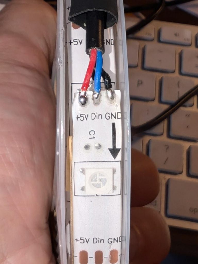
also known as “Monster BASICS Sound reactive RGB+IC Color Flow LED strip”. It’s $5 or so at Dollarama, and includes a USB cable for power and a remote control. It’s two metres long and includes 60 RGB LEDs. Are these really super-cheap NeoPixel clones?
I’m going to keep the USB power so I can power it from a power bank, but otherwise convert it to a string of smart LEDs. We lose the remote control capability.
Pull back the heatshrink at the USB end:
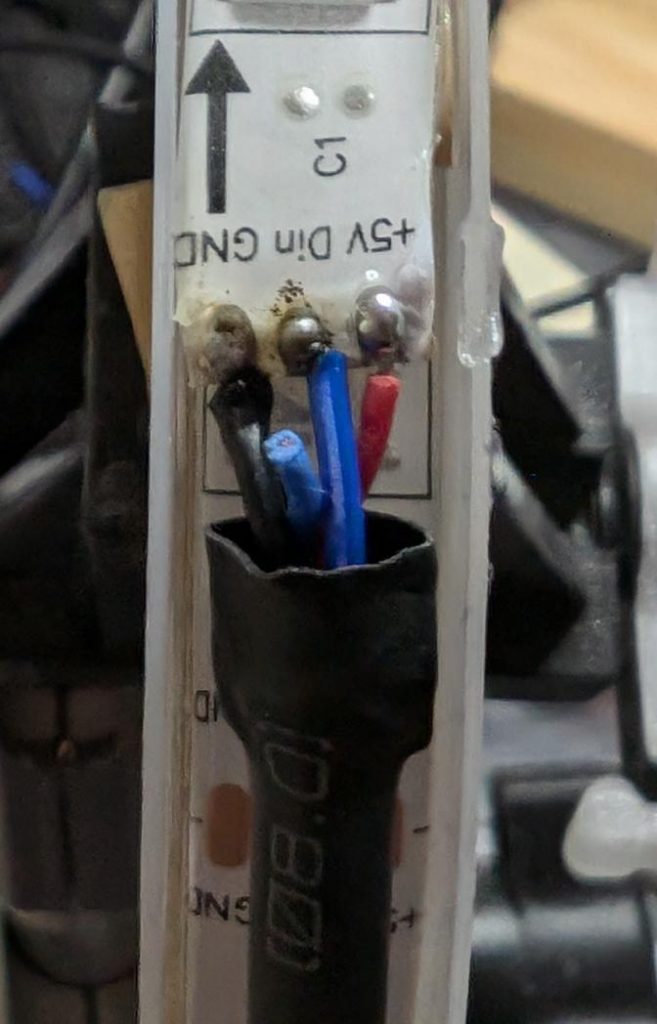
… and there are our connectors. We want to disconnect the blue Din (Data In) line from the built in controller, and solder new wires to Din and GND to run from a microcontroller board.
Maybe not the best solder job, but there are new wires feeding through the heatshrink and soldered onto the strip.
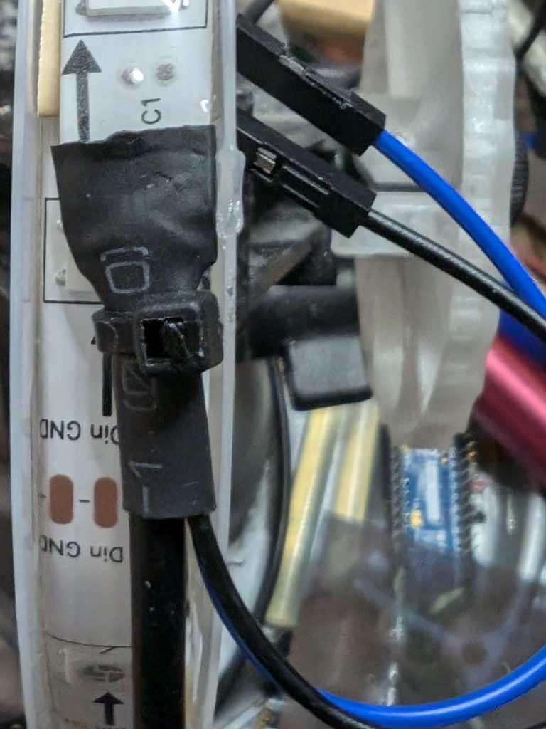
Here’s the heatshrink pushed back, and everything secured with a cable tie.
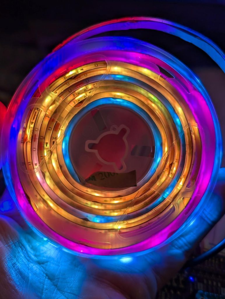
Now to feed it from standard MicroPython NeoPixel code, suitably jazzed up for 60 pixels.
So you bought that Brother laser printer like everyone told you to. And now it’s out of toner, so you replaced the cartridge. If you were in the USA, you could return the cartridge for free using the included label. But in Canada … it’s a whole deal including registering with Brother and giving away your contact details and, and, and …
I’m pretty sure this is a generic label, since:
the file is dated sometime in 2023, and wasn’t generated directly for my download;
I got a different tracking number when I handed the thing in at the post office.
Stewart Russell – scruss.com — 2024-03-26, at age 19999 days …
Summary
One’s thousand day(s) celebration occurs every thousand days of a person’s life. They are meant to be a recognition of getting this far, and are celebrated at the person’s own discretion.
Who is this for?
Maybe your birthday’s on a day associated with an unpleasant event. Your thousand day will never coincide with your birthday.
Maybe your birthday’s in the middle of winter, or in another part of the year that you’re not keen on. Your thousand day is every 2 years and 3 seasons, so it shifts back by a season every time it happens.
Quantities and scale
1000 days is approximately:
2.738 years
2 years 269 days
2 years 8.85 months
2 years, 3 seasons.
4000 days is just shy of 11 years.
Disadvantages
Compared to regular birthdays, thousand days:
must be calculated; they’re not intuitive when they’re going to happen. But we have computers and calendar reminders for that …
can be used to work out your actual date of birth, if someone knows that you’re going to be x000 days old on a particular day. It’s possible to know someone’s birthday, but not know their age.
There are no trademarks, patents, official websites, social media or official anythings attached to this concept. Please take the idea and do good with it.
So why aren’t you implementing this further?
I’ve had this idea kicking around my head for at least the last 20 years. For $REASONS, it turns out I’m not very good at implementing stuff. I’d far rather someone else took this idea and ran with it than let it sit undeveloped.
It’s mid-February in Toronto: -10 °C and snowy. The memory of chirping summer fields is dim. But in my heart there is always a cricket-loud meadow.
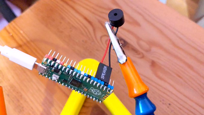
Short of moving somewhere warmer, I’m going to have to make my own midwinter crickets. I have micro-controllers and tiny speakers: how hard can this be?
more fun than a bucket of simulated crickets (video description: a plastic box containing three USB power banks, each with USB cable leading to a Raspberry Pi Pico board. Each board has a small electromagnetic speaker attached between ground and a data pin)
I could have merely made these beep away at a fixed rate, but I know that real crickets tend to chirp faster as the day grows warmer. This relationship is frequently referred to as Dolbear’s law. The American inventor Amos Dolbear published his observation (without data or species identification) in The American Naturalist in 1897: The Cricket as a Thermometer —
pretty bold assertions there without data eh, Amos old son …?
When emulating crickets I’m less interested in the rate of chirps per minute, but rather in the period between chirps. I could also care entirely less about barbarian units, so I reformulated it in °C (t) and milliseconds (p):
t = ⅑ × (40 + 75000 ÷ p)
Since I know that the micro-controller has an internal temperature sensor, I’m particularly interested in the inverse relationship:
p = 15000 ÷ (9 * t ÷ 5 – 8)
I can check this against one of Dolbear’s observations for 70°F (= 21⅑ °C, or 190/9) and 120 chirps / minute (= 2 Hz, or a period of 500 ms):
Now I’ve got the timing worked out, how about the chirp sound. From a couple of recordings of cricket meadows I’ve made over the years, I observed:
The total duration of a chirp is about ⅛ s
A chirp is made up of four distinct events:
a quieter short tone;
a longer louder tone of a fractionally higher pitch;
the same longer louder tone repeated;
the first short tone repeated
There is a very short silence between each tone
Each cricket appears to chirp at roughly the same pitch: some slightly lower, some slightly higher
The pitch of the tones is in the range 4500–5000 Hz: around D8 on the music scale
I didn’t attempt to model the actual stridulating mechanism of a particular species of cricket. I made what sounded sort of right to me. Hey, if Amos Dolbear could make stuff up and get it accepted as a “law”, I can at least get away with pulse width modulation and tiny tinny speakers …
This is the profile I came up with:
21 ms of 4568 Hz at 25% duty cycle
7 ms of silence
28 ms of 4824 Hz at 50% duty cycle
7 ms of silence
28 ms of 4824 Hz at 50% duty cycle
7 ms of silence
21 ms of 4568 Hz at 25% duty cycle
7 ms of silence
That’s a total of 126 ms, or ⅛ish seconds. In the code I made each instance play at a randomly-selected relative pitch of ±200 Hz on the above numbers.
For the speaker, I have a bunch of cheap PC motherboard beepers. They have a Dupont header that spans four pins on a Raspberry Pi Pico header, so if you put one on the ground pin at pin 23, the output will be connected to pin 26, aka GPIO 20:
# cricket thermometer simulator - scruss, 2024-02
# uses a buzzer on GPIO 20 to make cricket(ish) noises
# MicroPython - for Raspberry Pi Pico
# -*- coding: utf-8 -*-

from machine import Pin, PWM, ADC, freq
from time import sleep_ms, ticks_ms, ticks_diff
from random import seed, randrange

freq(125000000)  # use default CPU freq
seed()  # start with a truly random seed
pwm_out = PWM(Pin(20), freq=10, duty_u16=0)  # can't do freq=0
led = Pin("LED", Pin.OUT)
sensor_temp = machine.ADC(4)  # adc channel for internal temperature
TOO_COLD = 10.0  # crickets don't chirp below 10 °C (allegedly)
temps = []  # for smoothing out temperature sensor noise
personal_freq_delta = randrange(400) - 199  # different pitch every time
chirp_data = [
    # cadence, duty_u16, freq
    # there is a cadence=1 silence after each of these
    [3, 16384, 4568 + personal_freq_delta],
    [4, 32768, 4824 + personal_freq_delta],
    [4, 32768, 4824 + personal_freq_delta],
    [3, 16384, 4568 + personal_freq_delta],
]
cadence_ms = 7  # length multiplier for playback


def chirp_period_ms(t_c):
    # for a given temperature t_c (in °C), returns the
    # estimated cricket chirp period in milliseconds.
    #
    # Based on
    # Dolbear, Amos (1897). "The cricket as a thermometer".
    #   The American Naturalist. 31 (371): 970–971. doi:10.1086/276739
    #
    # The inverse function is:
    #     t_c = (75000 / chirp_period_ms + 40) / 9
    return int(15000 / (9 * t_c / 5 - 8))


def internal_temperature(temp_adc):
    # see pico-micropython-examples / adc / temperature.py
    return (
        27
        - ((temp_adc.read_u16() * (3.3 / (65535))) - 0.706) / 0.001721
    )


def chirp(pwm_channel):
    for peep in chirp_data:
        pwm_channel.freq(peep[2])
        pwm_channel.duty_u16(peep[1])
        sleep_ms(cadence_ms * peep[0])
        # short silence
        pwm_channel.duty_u16(0)
        pwm_channel.freq(10)
        sleep_ms(cadence_ms)


led.value(0)  # led off at start; blinks if chirping
### Start: pause a random amount (less than 2 s) before starting
sleep_ms(randrange(2000))

while True:
    loop_start_ms = ticks_ms()
    sleep_ms(5)  # tiny delay to stop the main loop from thrashing
    temps.append(internal_temperature(sensor_temp))
    if len(temps) > 5:
        temps = temps[1:]
    avg_temp = sum(temps) / len(temps)
    if avg_temp >= TOO_COLD:
        led.value(1)
        loop_period_ms = chirp_period_ms(avg_temp)
        chirp(pwm_out)
        led.value(0)
        loop_elapsed_ms = ticks_diff(ticks_ms(), loop_start_ms)
        sleep_ms(loop_period_ms - loop_elapsed_ms)
There are a few more details in the code that I haven’t covered here:
The program pauses for a short random time on starting. This is to ensure that if you power up a bunch of these at the same time, they don’t start exactly synchronized
The Raspberry Pi Pico’s temperature sensor can be slightly noisy, so the chirping frequency is based on the average of (up to) the last five readings
There’s no chirping below 10 °C, because Amos Dolbear said so
The built-in LED also flashes if the board is chirping. It doesn’t mimic the speaker’s PWM cadence, though.
Before I show you the next video, I need to say: no real crickets were harmed in the making of this post. I took the bucket outside (roughly -5 °C) and the “crickets” stopped chirping as they cooled down. Don’t worry, they started back up chirping again when I took them inside.
“If You’re Cold They’re Cold, Bring Them Inside” (video description: a plastic box containing three USB power banks, each with USB cable leading to a Raspberry Pi Pico board. Each board has a small electromagnetic speaker attached between ground and a data pin)


![[decorative] a spiralling figure made of scaled and rotated equilateral triangles](https://scruss.com/wordpress/wp-content/uploads/2025/04/hpgl-rotatey.png)
![[decorative] a spiralling figure made of scaled and rotated equilateral triangles](https://scruss.com/wordpress/wp-content/uploads/2025/04/20250408_214147_BRWD89C6730425A_000572a-787x1024.jpg)