#swagfail

Put me out to pasture, my conference swag skills are failing.

I picked this up at Solar Power International:

I thought I was picking up a USB memory stick, as I’d nabbed one in the same form factor before. Break off the backing card at the hinge, and you’ve got a nice tiny data store like the Kingmax ones I used to use.

On plugging it into my Mac, a couple of icons bipped on my dock, then Skype opened. Wat? More importantly, there was no storage to be seen, so once my virus fears had subsided a bit, I was determined to find out what this pointless piece of plastic was doing.

The stick identified itself to the system as an Apple keyboard (USB ID 05ac:020b), and spits out the following characters (captured by cat and xxd on my Raspberry Pi):

0000000: 1b72 1b5b 317e 1b5b 3477 7777 2e62 757a  .r.[1~.[4www.buz
0000010: 7a63 6172 642e 7573 2f73 6365 2d32 3230  zcard.us/sce-220
0000020: 0a                                       .

After reading about evil USB dongles, it seems that the Ctrl-R keypress it’s sending is the Windows “Open Browser” command, and then opens the url www.buzzcard.us/sce-220. This link redirects to www.plugyourbrand.com/gosolar_sce/index.html?u=220, which appears to do some Flash/JS stuff which I don’t want to understand.

The funny thing is, the card has the perfectly respectable www.GoSolarCalifornia.ca.gov (well, respectable if you consider a US .gov website as such) link printed on it. Even printing a card with a QR code linking to that address would be less opaque.

(This is not a link to goatse, honest.)

As is, a bunch of plastic was wasted in vain just to save people typing an URL. We’re all going to die, and it really is your fault …

(sort-of) Solar Powered Raspberry Pi

One day, I’d like to power a small remote server from solar power. Today is not yet that day. But I’m closer …

At the Solar Power International show (big modules! cheap modules! AC modules!!) last week in Orlando (squee-able minilizards! cuban food!!) there were a few vendors selling solar USB chargers. Most were folding thin-film units similar to this, but what caught my eye (and was actually for sale at the show) was the LSTechSmart one“: The unit features:

  • 2× 3.5 Ah 3.7 V Li-Poly batteries
  • a 4W 5V solar panel inside the clamshell case
  • a 1A USB output
  • a USB Micro-B charging input and auxiliary solar panel input
  • two ah-oww, make-it-stop bright LED interrogation reading lights.

It comes with a couple of USB cables, and like seemingly all Korean semi-luxe electronic devices, comes in a soft brown velour bag. I’m not sure if the soft velour bag is the universal sign of quality in Korea, but I’ve noticed it enough that it might be A Thing.

I’ve run a Raspberry Pi for a couple of hours off this thing without making too much of a dent in the charge. I might be able to run it in full sun from the 4W solar charger, but I’m under no illusion that the Raspberry Pi’s ~3.5W continuous draw is going to keep running from such a small panel. That’s expecting an 88% capacity factor from a solar panel, which would be well if there wasn’t this small thing called night (or rotation of the earth, or cloud cover, or …)

Pibow; it’s official – normal USB cables don’t fit

I’d noted previously that a standard USB micro-b power plug doesn’t fit into a Pibow. I’ve measured the opening in the case at 10.4 mm. This is what the USB.org spec says for the Micro-B plug:

A conforming cable can be up to 0.2mm larger than would fit into the Pibow. The rather weak excuse given by the designer is:

My Micro-USB cable doesn’t fit!

The Pibow supports a wide range of svelte, stylish micro USB cables, we recommend on [sic] of these. We may be able to slightly widen the aperture to include more cable. We don’t intend to support cables with large sleeves though, they just look naff 🙁

While I had the vernier calipers out, I measured all the USB connectors I could find. Not one was under 11 mm, way out of spec, and completely unlikely to fit in the Pibow.

Pibow

… arrived today from the UK. Quick and easy build, though you have to be careful to get the case screws all tightened up just right or the thing will be wobbly. IKEA are totally going to hand Pimoroni their arse over the lookalike instructions, though.

Though there is just one problem: a standard USB micro-b power plug doesn’t fit …

Raspberry Pi, Python & Arduino *and* a GUI …

Whee! This entry was the basis of the cover article of The MagPi issue 7. Read it on Issuu, or download the PDF.

Okay, so maybe I can stop answering the StackExchange question “How to attach an Arduino?” now. While I got the Arduino working with pyFirmata on the Raspberry Pi before, it wasn’t that pretty. With a TkInter front end, it actually looks like some effort was involved. You can happily brighten and dim the LED attached to the Arduino all you want, while the temperature quietly updates on the screen independent of your LED frobbing.

I’d never used TkInter before. For tiny simple things like this, it’s not that hard. Every widget needs a callback; either a subroutine it calls every time it is activated, or a variable that the widget’s value is tied to. In this case, the Scale widget merely calls a function set_brightness() that sets a PWM value on the Arduino.

Updating the temperature was more difficult, though. After TkInter has set up its GUI, it runs in a loop, waiting for user events to trigger callback events. It doesn’t really allow you to run another loop alongside its main event loop. What you have to do then is set up a routine which is called periodically using TkInter’s after() function, which calls a subroutine after a set amount of time. If this subroutine ends with another call to after() to call itself again, it will maintain its own event loop separate from TkInter’s GUI loop. This is what I do in the get_temp() subroutine, which schedules itself after a ½ second.


#!/usr/bin/python
# -*- coding: utf-8 -*-

# graphical test of pyfirmata and Arduino; read from an LM35 on A0,
#                                          brighten an LED on D3 using PWM
# Connections:
# - small LED connected from D3, through a 1kΩ resistor to GND;
# - LM35: +Vs -> +5V, Vout -> A0, and GND -> GND.
# scruss, 2012-08-16 - tested on Raspberry Pi and Arduino Uno

import pyfirmata
import sys                              # just for script name and window
from Tkinter import *

# Create a new board, specifying serial port
board = pyfirmata.Arduino('/dev/ttyACM0')

# start an iterator thread so that serial buffer doesn't overflow
it = pyfirmata.util.Iterator(board)
it.start()

# set up pins
pin0=board.get_pin('a:0:i')             # A0 Input      (LM35)
pin3=board.get_pin('d:3:p')             # D3 PWM Output (LED)

# IMPORTANT! discard first reads until A0 gets something valid
while pin0.read() is None:
    pass

def get_temp():                         # LM35 reading in °C to label
    selection = "Temperature: %6.1f °C" % (pin0.read() * 5 * 100)
    label.config(text = selection)
    root.after(500, get_temp)           # reschedule after half second

def set_brightness(x):  # set LED; range 0 .. 100 called by Scale widget
    y=float(x)
    pin3.write(y / 100.0)               # pyfirmata expects 0 .. 1.0

def cleanup():                          # on exit
    print("Shutting down ...")
    pin3.write(0)                       # turn LED back off
    board.exit()

# now set up GUI
root = Tk()
root.wm_title(sys.argv[0])              # set window title to program name
root.wm_protocol("WM_DELETE_WINDOW", cleanup) # cleanup called on exit
scale = Scale( root, command=set_brightness, orient=HORIZONTAL, length=400,
               label='Brightness')      # a nice big slider for LED brightness
scale.pack(anchor=CENTER)

label = Label(root)
label.pack(anchor='nw')                 # place label up against scale widget

root.after(500, get_temp)               # start temperature read loop
root.mainloop()

The program takes a few seconds to start on the Raspberry Pi, mainly because initializing pyFirmata over a serial line and waiting for the duff values to subside takes time. I tried to exit the program gracefully in the cleanup() subroutine, but sometimes one of the loops (I suspect pyFirmata’s iterator) doesn’t want to quit, so it takes a few clicks to exit.

The program also seems to chew up a fair bit of CPU on the Raspberry Pi; I had it at around 40% usage just sitting idle. I guess those serial ports don’t read themselves, and you have to remember that this computer is basically no more powerful than a phone.

So there you are; a simple demo of how to control an output and read an input on an Arduino, from a Raspberry Pi, written in Python (the Raspberry Pi’s official language) with a simple GUI. Considering I’d never written a line of Python before the beginning of this month, I think I’m doing not too badly.

Raspberry Pi, Python & Arduino

Hey! This article is really old! So old, in fact, that it really only exists to track down content farms that like to knock off my articles (oh hai, CircuitDigest!). Information here may be misleading and possibly wrong. You probably want to be using a newer client library and you definitely want to use an Arduino IDE ≥ 1.6 and not the ancient one that comes with Raspbian.

After the other night’s wonderfully slow detour into Processing, I thought I’d try the Raspberry Pi’s “native” language of Python to control an Arduino. This worked rather well, though I don’t have a slick GUI for it yet.

pyFirmata is the magic that allows an Arduino running Firmata to talk to Python. It’s fairly easy to install under Raspbian:

  1. Get the required packages:
    sudo apt-get install python-serial mercurial
  2. Download the pyFirmata code:
    hg clone https://bitbucket.org/tino/pyfirmata
    cd pyfirmata
    sudo python setup.py install

    (If this succeeds, you can delete the pyfirmata folder.)

Using pyFirmata is a bit different from other Arduino applications:

  • Analogue reads and PWM writes are normalized to a 0 .. 1 range, and not the standard Arduino 0 .. 255 and 0 .. 1023.
  • You really need to start a separate iterator thread to stop old readings overflowing the serial buffer
  • Since the Arduino is read asynchronously, make sure that the pyFirmata connection is fully initialized before reading from ports. Otherwise, None values ensue.

Here’s some code that uses the same hardware as before, but simply reports the temperature and ramps the brightness of the LED up in 10% steps.

#!/usr/bin/python
# -*- coding: utf-8 -*-

# simple test of pyfirmata and Arduino; read from an LM35 on A0,
#                                       brighten an LED on D3 using PWM
# scruss, 2012-08-14 - tested on Arduino Uno & Raspberry Pi (Raspbian)

import pyfirmata

# Create a new board, specifying serial port
board = pyfirmata.Arduino('/dev/ttyACM0')

# start an iterator thread so that serial buffer doesn't overflow
it = pyfirmata.util.Iterator(board)
it.start()

# set up pins
pin0=board.get_pin('a:0:i')             # A0 Input      (LM35)
pin3=board.get_pin('d:3:p')             # D3 PWM Output (LED)

# IMPORTANT! discard first reads until A0 gets something valid
while pin0.read() is None:
    pass

for i in range(10):
    pin3.write(i/10.0)                  # set D3 to 0, 10%, 20%, ... brightness
    print "PWM: %d %% Temperature %.1f °C" % (i * 10, pin0.read() * 5 * 100)
    board.pass_time(1)                  # pause 1 second

pin3.write(0)                           # turn LED back off
board.exit()

The output from this might look like:

PWM: 0 % Temperature 24.9 °C
PWM: 10 % Temperature 24.9 °C
PWM: 20 % Temperature 24.9 °C
PWM: 30 % Temperature 25.9 °C  <-
PWM: 40 % Temperature 26.9 °C    |
PWM: 50 % Temperature 28.3 °C    | I was holding the LM35 here
PWM: 60 % Temperature 28.8 °C    | to make the temperature rise
PWM: 70 % Temperature 29.8 °C    |
PWM: 80 % Temperature 29.8 °C    | 
PWM: 90 % Temperature 29.8 °C  <-

If this doesn’t work, check the output of dmesg to see if you’re using the right port. You could try this little test script

#!/usr/bin/python
# -*- coding: utf-8 -*-

import pyfirmata

PORT = '/dev/ttyACM0'           # change this to suit
board = pyfirmata.Arduino(PORT)
print 'pyFirmata version:\t%s' % pyfirmata.__version__
print 'Hardware:\t\t%s' % board.__str__()
print 'Firmata firmware:\t%i.%i' % (board.get_firmata_version()[0],
                                    board.get_firmata_version()[1])
board.exit()

which should generate something like

pyFirmata version:    0.9.4
Hardware:        Arduino /dev/ttyACM0 on /dev/ttyACM0
Firmata firmware:    2.3

Next time, I’ll try to wrap this in a tkinter GUI. But for now, pyFirmata is a much quicker way than Processing to talk to an Arduino. But there is hope of a faster Java for the Raspberry Pi

Controlling an Arduino from Raspberry Pi using Processing

Hey! This article is really old! The code might still work, but I’ve updated the installation instructions for Processing 2.1 and Sun Oracle Java here: Processing 2.1 + Oracle Java + Raspberry Pi + Serial + Arduino = ☺.

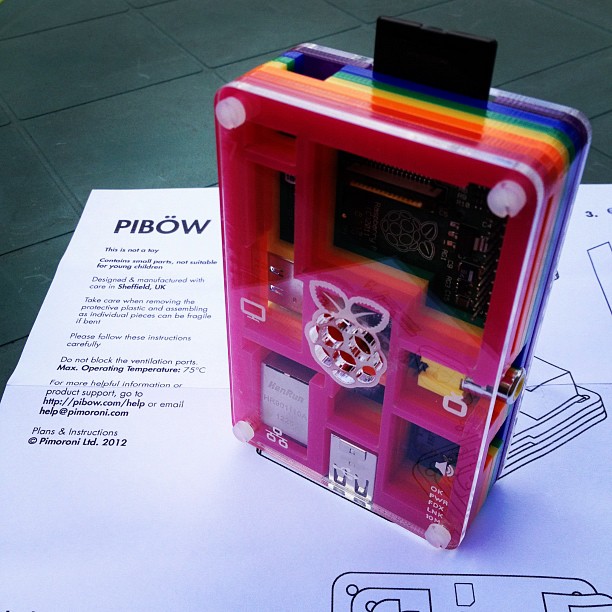
This might not look like much, but it was a lot of work to get here. It’s the display from a small Processing sketch, running on a Raspberry Pi, talking to an Arduino controlling the brightness of an LED with the slider, and reading from an LM35 temperature sensor.

I wanted to see if I could get graphical control of an Arduino on the Raspberry Pi. I wrote about the simplest sketch in Processing that combined output (to control a small green LED through a resistor) and input (from an LM35, that simplest of sensors). This is how it looks running on a slightly faster machine than the Raspberry Pi:

LED at half brightness, LM35 showing 25°C

LED off, sensor at 26°C

LED full on, LM35 warmed up

I had the same results on the Raspberry Pi; just much, much slower. The sketch is below the fold.

Running Processing on Raspberry Pi

Processing is both written in and generates Java, so there’s some hope that it can run on most platforms. Up-to-date installation instructions. These instructions are modified from Processing sur Raspberry Pi, for which thanks are given to the original author:

  1. Install the JDK and Java serial library: sudo apt-get install librxtx-java openjdk-6-jdk
  2. Download the Linux version of Processing, and unpack it to somewhere permanent in your home directory
  3. Delete the java folder in the Processing directory; for me, that was processing-1.5.1/java
  4. Replace that java folder with a link to your system’s installation: ln -s /usr/lib/jvm/java-6-openjdk-armhf java
  5. In the Processing folder, remove or rename modes/java/libraries/serial/library/linux32/librxtxSerial.so; it’s an x86 binary, and will fail
  6. In the Processing folder, also remove modes/java/libraries/serial/library/RXTXcomm.jar, and replace it with a copy of /usr/share/java/RXTXcomm.jar
    (If you don’t do this, you’ll get a warning: “WARNING:  RXTX Version mismatch”, and any serial comms will fail.)
  7. Download and install the controlP5 library for Processing
  8. Download and install the Arduino library for Processing
  9. Program your Arduino with Firmata; the version that comes with the Arduino software is fine a bit old.
  10. Connect your Arduino to the Raspberry Pi with a USB cable; it may require external power.

Now fire up Processing. It will used to take a while to start up, and will throw the following warning:

Despite this, it should eventually should start up fine:

Now, this is slow. It takes tens of seconds to start up. It might not be the most practical development tool, but Processing sketches are very portable, so you can develop on one machine, and then run on the Raspberry Pi.

The code at the end of this article expects:

  • an Arduino running the Firmata DAQ sketch attached to a USB port;
  • a small LED connected from digital pin 3, through a 1kΩ resistor to ground;
  • an LM35 with the following connections: +Vs → +5V, Vout → analogue pin 0, and GND → GND.

If you run this, after about half a minute, the blank sketch window appears, and about half a minute later, the slider and temperature reading appears. If it doesn’t, there’s a good chance that the serial libraries are wrong. Try this sketch:

import processing.serial.*;
import cc.arduino.*;

Arduino arduino;
println(Arduino.list());

This should return a number and a serial port where the Arduino was found; something like ‘[0] /dev/ttyACM0’.

What I really want to do now is get this same hardware running with Python and tkinter. It’s not that Python’s my favourite language; it’s just that the Raspberry Pi Foundation chose Python as the official language for the board. I’d rather work to further the aims of this educational foundation rather than work against it. Processing’s pretty much unworkably slow on the Raspberry Pi — but it does work!

ssh … you know who

In a moment of boredom, I tried to bring up an X session on my Raspberry Pi from my laptop in the hotel, via the machine in the DMZ on my home network. It worked! It’s not very fast, but proves it can be done. The command I used was:

ssh -X home_dmz_machine 'ssh -X raspberrypi "exec startlxde"'

Pi Sandwich

I retired the cardboard case this morning, as I got some proper enclosures:

Looks a bit like a little red Orac, no?

This case is a Bud Industries Pi Sandwich. They’re cheap ($5) but very basic. Comprised of two identical halves, you could (if you weren’t fussy about having the top off) house two Raspberry Pis in a single case.

The downsides are:

  • The clip retainers aren’t that tough, and the computer board can pop out under minor torsion. Make sure you’re supporting the board while you’re putting in the connectors.
  • The box is taller than it needs to be. While this is great for giving space for GPIO cables, there’s a big empty space underneath. I wonder if there’s enough room to jam in a LiPo battery, a DC charger and a Minty Boost-like thing to act as a mini-UPS, with the board lying on top?
    (This device would of course be called a llow, so it would be a Raspberry Pillow. Ahem.)
  • The really nice flat acryllic box sits so flat on smooth surfaces, it sticks, yet still slides about. Sticky feet would help.

It’s a case. It stops the Raspberry Pi shorting out or getting too dusty/things spilled on it. It’s cheap. It works. I’m happy with it.

learning to tolerate python

Python is okay, I guess, but there’s not a hint of music to it. I’m a dyed-in-the-wool Perl programmer since 4.036 days. When I think of how I’ll solve a programming problem, I think in Perl (or, more rarely, in PostScript, but I really have to be pretty off-balance to be thinking in stacks). I’m learning Python because all of the seemingly nifty open source geospatial software uses it, and if I’m to write anything for or about the Raspberry Pi, it seems that Python is the language they officially support on it.

So I’m learning Python by porting some of the simple Perl tools I use around here. It’s painful, not just dealing with the language Fortranesque space-significance, but also physically; I think I put my shoulder out picking up Mark Lutz‘s giant books on Python. The first program I chose to port matches input lines against known words in the system dictionary file. Here’s the Perl version:

#!/usr/bin/perl -w

use strict;
use constant WORDLIST => '/usr/share/dict/words';

my %words;
open(WORDS, WORDLIST);
while () {
    chomp;
    my $word  = lc($_);
    $words{$word}++;
}
close(WORDS);

# now read candidate words from stdin
while (<>) {
  chomp;
  $_=lc($_);
  print $_,"\n" if defined($words{$_});
}

exit;

I most recently used this to look for available call signs that — minus the number — were real words. The input lines from the available call sign list look like this:

VA3PHZ
VA3PIA
VA3PID
VA3PIF
VA3PIH
...

so if I strip out the 3s and run it through the program:

sed 's/3//;' va3_avail.txt | ./callsigncheck.pl

I get one hit: vapid. Which is now my call sign, VA3PID. Moohah.

The Python version is much shorter, and I’m semi-impressed with the nifty little trick in line 5 (aka ‘dictionary comprehension’) which offers some hope for the future of terse, idiomatic code. The fileinput module gives Perlish stdin-or-ARGV[] file input, without which I’m sunk.

#!/usr/bin/python
import fileinput                        # Perl-like file input

# get our wordlist
words={w.lower(): 1 for w in open('/usr/share/dict/words', 'r').read().split()}

# read through input looking for matching words
for l in fileinput.input():
    ll=l.lower().rstrip()
    if words.get(ll, 0):
        print(ll)

(So far, I’ve found the PLEAC – Programming Language Examples Alike Cookbook useful in comparing the languages.)

Raspbian ftw!

Raspbian is good. If you haven’t upgraded your Raspberry Pi to run it — or any other hard float distro — then you should. It makes the little board seem positively zippy.

The processor on the Pi is an odd beast. It’s an ARMv6, somewhere between the ARMv5 that the original Debian distro supported, and the ARMv7, which has to have hardware floating point support. The Pi’s processor has floating point in hardware, but it wasn’t supported in the first distribution. Raspbian fixes this, and also has a nice hardware setup wizard (which I wish I’d known about before I spent a while preconfiguring the SD card on another Linux box, grr).

My highly unscientific benchmark of how fast a computer is is encoding an audio file with ‘lame -V2′. If it comes out faster than real time, it’s fast enough. My first trial in late June came out at a dismal 27% real time — so that would mean that a 4 minute song would take 14′ 49″ to encode. Very poor. Trying it again with Raspbian today gave me 209% real time — so that same song would be done in 1′ 55″. Much better.

While I was fossicking about with the Pi, I switched its power adapter over to a battery-backed outlet on my UPS. With summer storms, our power has been a bit glitchy, and the tiny USB power supply wasn’t able to ride through any of them. This, I hope, will allow me to have an uptime better than the time between storms …

I also made this last week:

It’s a GPIO breakout, a sort of home made Adafruit Pi Cobbler. It’s on a tiny 13×4 fragment of stripboard. The soldering was fiddly, as stripboard is only single sided, so there was much fine tipped soldering iron action (and swearing). I now have the parts to built Mike Cook’s Breakout board with zener diodes providing protection, but this will do for simple applications if I’m careful.

not overthinking Raspberry Pi enclosures one bit …

I was half way through marking out the Raspberry Pi‘s shipping box to cut out as an enclosure

rpi shipping box

… when I spotted a SparkFun box from an Arduino shield. Aha! Nice thick corrugated card that was reasonably easy to cut with a very sharp knife.

fits nicely

<voice_of_experience>NB: At this point it would have been much wiser to have inserted a memory card before laying this out.</voice_of_experience>

cut out slots for connectors on lid

You’re going to have to cut out slots for connectors on the side of the lid. I marked out the path of the lid by closing the box and shading the path that went by the hole I’d cut. Basically, any cardboard you see passing by the hole has to be cut out.

now with memory card

Now with memory card — and you can see I was a bit off.

the pain of misalignment

The pain of misalignment, as seen by the HDMI plug. Knives out!

finally all snugged into the box

It’s finally all snugged into the box. It’s not going to move about with all the connectors holding it in place.

don't forget the cutout for the video cable

Don’t forget the cutout for the video cable in the box flap. I only caught this at the very last moment.

The Raspberry Pi does run faintly warm in the box. I suspect with the warmth, and all the little cutouts, this will shortly become an A-1 Special spider habitat.