Simple ADC with the Raspberry Pi

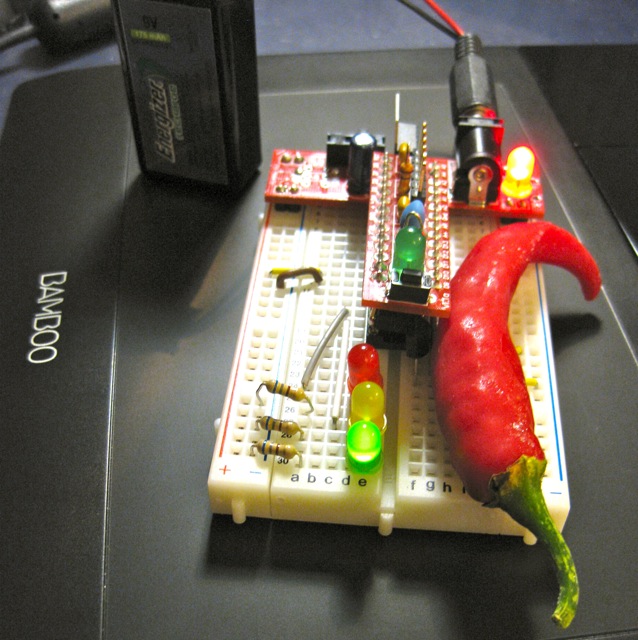
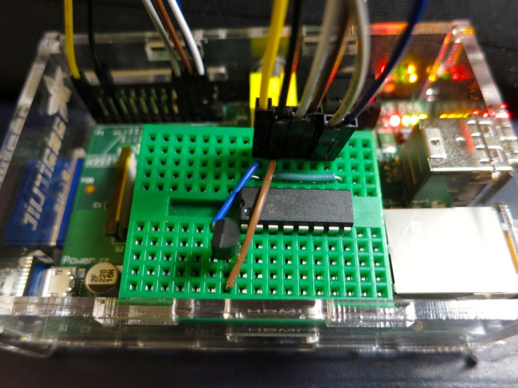
Raspberry Pi wearing an MCP3008

Hey! This is a really old article. You should really be using gpiozero these days.

I hadn’t realised it, but the The Quite Rubbish Clock did something that a lot of people seem to have trouble with on the Raspberry Pi: communicating using hardware SPI. Perhaps it’s because everything is moving so fast with Raspberry Pi development, tutorials go out of date really quickly. Thankfully, hardware SPI is much easier to understand than the older way of emulation through bit-banging.

SPI is a synchronous serial protocol, so it needs a clock line as well as a data in and data out line. In addition, it has a Chip Enable (CE, or Chip Select, CS) line that is used to choose which SPI device to talk to. The Raspberry Pi has two CE lines (pins 24 and 26) so can talk to two SPI devices at once. It supports a maximum clock rate of 32 MHz, though in practice you’ll be limited to the rate your device supports.

The device I’m testing here is an MCP3008 10-bit Analogue-to-Digital Converter (ADC). These are simple to use, cheap and quite fast converters with 8 input channels. If you hook them up to a 3.3 V supply they will convert a DC voltage varying from 0-3.3 V to a digital reading of 0-1023 (= 210 – 1). Not quite up there in quality for hi-fi audio or precision sensing, but good enough to read from most simple analogue sensors.

The sensor I’m reading is the astonishingly dull LM35DZ temperature sensor. All the cool kids seem to be using TMP36s (as they can read temperatures below freezing without a negative supply voltage). One day I’ll show them all and use a LM135 direct Kelvin sensor, but not yet.

To run this code, install the SPI libraries as before. Now wire up the MCP3008 to the Raspberry Pi like so:

 MCP 3008 Pin          Pi GPIO Pin #    Pi Pin Name
==============        ===============  =============
 16  VDD                 1              3.3 V
 15  VREF                1              3.3 V
 14  AGND                6              GND
 13  CLK                23              GPIO11 SPI0_SCLK
 12  DOUT               21              GPIO09 SPI0_MISO
 11  DIN                19              GPIO10 SPI0_MOSI
 10  CS                 24              GPIO08 CE0
  9  DGND                6              GND

The wiring for the LM35 is very simple:

 LM35 Pin        MCP3008 Pin
==========      =============
 Vs              16 VDD
 Vout             1 CH0
 GND              9 DGND

The code I’m using is a straight lift of Jeremy Blythe’s Raspberry Pi hardware SPI analog inputs using the MCP3008. The clever bit in Jeremy’s code is the readadc() function which reads the relevant length of bits (by writing the same number of bits; SPI’s weird that way) from the SPI bus and converting it to a single 10-bit value.

#!/usr/bin/python
# -*- coding: utf-8 -*-
# mcp3008_lm35.py - read an LM35 on CH0 of an MCP3008 on a Raspberry Pi
# mostly nicked from
#  http://jeremyblythe.blogspot.ca/2012/09/raspberry-pi-hardware-spi-analog-inputs.html

import spidev
import time

spi = spidev.SpiDev()
spi.open(0, 0)

def readadc(adcnum):
# read SPI data from MCP3008 chip, 8 possible adc's (0 thru 7)
    if adcnum > 7 or adcnum < 0:
        return -1
    r = spi.xfer2([1, 8 + adcnum << 4, 0])
    adcout = ((r[1] & 3) << 8) + r[2]
    return adcout

while True:
    value = readadc(0)
    volts = (value * 3.3) / 1024
    temperature = volts / (10.0 / 1000)
    print ("%4d/1023 => %5.3f V => %4.1f °C" % (value, volts,
            temperature))
    time.sleep(0.5)

The slightly awkward code temperature = volts / (10.0 / 1000) is just a simpler way of acknowledging that the LM35DZ puts out 10 mV (= 10/1000, or 0.01) per °C. Well-behaved sensors generally have a linear relationship between what they indicate and what they measure.

If you run the code:

sudo ./mcp3008_lm35.py

you should get something like:

  91/1023 => 0.293 V => 29.3 °C
  93/1023 => 0.300 V => 30.0 °C
  94/1023 => 0.303 V => 30.3 °C
  95/1023 => 0.306 V => 30.6 °C
  96/1023 => 0.309 V => 30.9 °C
  97/1023 => 0.313 V => 31.3 °C
  97/1023 => 0.313 V => 31.3 °C
  98/1023 => 0.316 V => 31.6 °C
  99/1023 => 0.319 V => 31.9 °C
  99/1023 => 0.319 V => 31.9 °C
 100/1023 => 0.322 V => 32.2 °C
 100/1023 => 0.322 V => 32.2 °C
 100/1023 => 0.322 V => 32.2 °C
 101/1023 => 0.325 V => 32.5 °C
 101/1023 => 0.325 V => 32.5 °C
 102/1023 => 0.329 V => 32.9 °C
 102/1023 => 0.329 V => 32.9 °C
 103/1023 => 0.332 V => 33.2 °C

Note that the sensor had been sitting over the Raspberry Pi’s CPU for a while; I don’t keep my house at 29 °C. I made the temperature go up by holding the LM35.

So, you’ve just (fairly cheaply) given your Raspberry Pi 8 analogue input channels, so it can behave much more like a real microcontroller now. I remember from my datalogging days that analogue inputs can be pretty finicky and almost always return a value even if it’s an incorrect one. Check the chip’s datasheet to see if you’re doing it right, and if in doubt, meter it!
Life with Ardweeny

I’m pretty new to Arduino, and electronics in general. Sure, I used to wire up sensors to a bunch of dataloggers, but there wasn’t much variation or application of theory. I made up a bunch of Ardweenies, mostly to practice soldering skills, but now I’ve made them, I might as well use them.

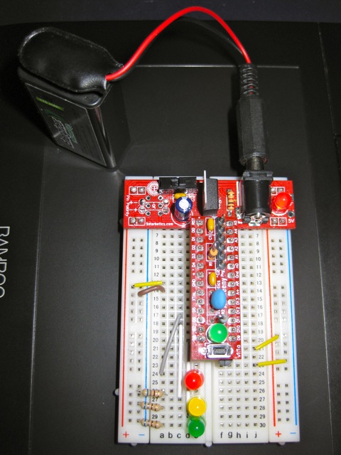
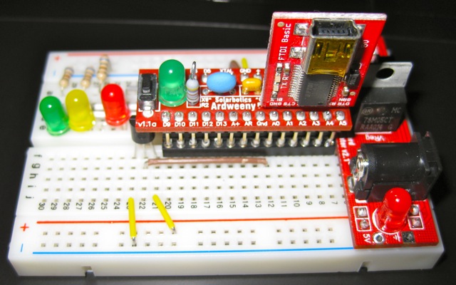
ardweeny, breadboard, USB programmer and PSU

The Ardweeny is a tiny broadboard-only Arduino-compatible microcontroller board. It needs both a power supply and a means of programming it. Solarbotics’ own Breadboard Voltage Regulator Kit provides the juice, while a SparkFun’s FTDI Basic Breakout handles the USB serial programming. The FTDI breakout board can supply power, so I turn the power off to the board at the regulator when programming it. You can’t use shields with the Ardweeny, but it’s small enough that you can have a simple project on a small breadboard. It communicates with the Arduino IDE as if it were a Duemilanove.

The Ardweeny has pins clearly (if tinily) marked by function. To power it, you need to feed GND and +. The familiar A0-A5 and D0-D13 are present, if not quite where you’d expect them. There isn’t room to mark the digital pins capable of PWM.

For no particular reason (perhaps that spring finally looks like it might be warming things up around here) I wanted to make a a temperature sensor that would sample the temperature at start up, then warn if the temperature got more than 2°C hotter or colder.

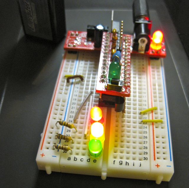
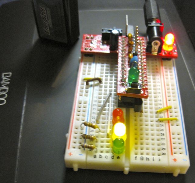
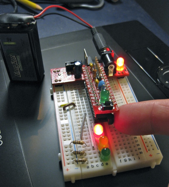
I used an LM35 as the sensor. These are a bit noisy, so I added some smoothing (nicked, with little grace, from the Arduino – Smoothing tutorial). The temperature is indicated by three LEDs: red for ≥2°C over, amber for within ±2°C of the starting temperature, and green for ≥2°C under. I also wanted all the LEDs lit while the system was working out starting temperature. Here’s how it runs:

starting up, showing all LEDs
showing normal temperature
warmed by a finger, showing ≥2°C over normal
chilled by a frozen cayenne (!), showing ≥2°C below normal

I put the LM35 on A0, and the red, amber and green LEDs on D5, D6 & D8. The only reason I didn’t use D7 was that I didn’t have the right length jumper wire. 680Ω resistors are used to limit current through the LEDs.

Here’s the code:

/*
 lm35_plusminus - read temperature at startup then light
 leds if over or under
 
 lm35 - analogue 0
 
 red led - digital 5
 amber led - digital 6
 green led - digital 8
 
 scruss - 2011-02-17
 */

#define REDPIN 5
#define AMBERPIN 6
#define GREENPIN 8
#define TEMPPIN 0 // analogue
#define DELTA 2.0 // amount +/- from start to warn
#define READINGS 15

//declare variables
float tempC, start_temp, array[READINGS], total;
int val, i;

void setup()
{
  pinMode(REDPIN, OUTPUT);
  pinMode(AMBERPIN, OUTPUT);
  pinMode(GREENPIN, OUTPUT);

  // signal start of test by lighting all LEDs
  digitalWrite(REDPIN, HIGH);
  digitalWrite(AMBERPIN, HIGH);
  digitalWrite(GREENPIN, HIGH);

  // read initial values
  for (i=0; i< READINGS; i++) {
    delay(500/READINGS); // just so initialization is visible
    val = analogRead(TEMPPIN);
    array[i] =  (5.0 * (float) val * 100.0)/1024.0;
    total += array[i];
  }
  start_temp = total / READINGS;

  // test off, lights off
  digitalWrite(REDPIN, LOW);
  digitalWrite(AMBERPIN, LOW);
  digitalWrite(GREENPIN, LOW);
  i=0; // just to initialize  
}

void loop()
{
  // some cheapo smoothing copied from the Smoothing example 
  //  in the playground
  total -= array[i];
  val = analogRead(TEMPPIN);
  tempC = (5.0 * (float) val * 100.0)/1024.0;
  array[i] = tempC;
  total += tempC;
  i++;
  if (i>=READINGS) {
    i=0;
  }
  tempC = total/READINGS;
  if (tempC - start_temp >= DELTA) {
    // we're hot !
    digitalWrite(REDPIN, HIGH);
    digitalWrite(AMBERPIN, LOW);
    digitalWrite(GREENPIN, LOW);
  }
  else if (tempC - start_temp <= -DELTA) {
    // we're cold !
    digitalWrite(REDPIN, LOW);
    digitalWrite(AMBERPIN, LOW);
    digitalWrite(GREENPIN, HIGH);
  }
  else {
    // we're just right !
    digitalWrite(REDPIN, LOW);
    digitalWrite(AMBERPIN, HIGH);
    digitalWrite(GREENPIN, LOW);
  }
}

Despite the smoothing, the LEDs flicker briefly as they turn on. I kind of like the effect, so I made no attempt to change it.

What I like about Arduino is that — within the limits of my sensor knowledge — the programming language does what I expect. The above program worked first time; worked, that is, save for me putting one LED in the wrong way round, so it didn’t light. I know I could probably replicate the same function with a few linear devices and other components, but it would take much more time and effort. It may not be the most elegant, but it does work,  and gives me the satisfaction of the desired result quickly.

big trouble in little microSD

It was a bit of a fight to get the SparkFun microSD Shield working. At first, I thought it was my choice of cards. Then, on reading the manual (ahem), I discovered the section “I downloaded a FAT library for Arduino on my own from the Web but it’s not working! Why not?“. It seems that the SparkFun shield uses non-standard pins for signalling, which they consider a feature, but some consider a bug.

After fixing the code in the awesome sdfatlib library, I’ve now got it logging the temperature of a cooling container of hot water:

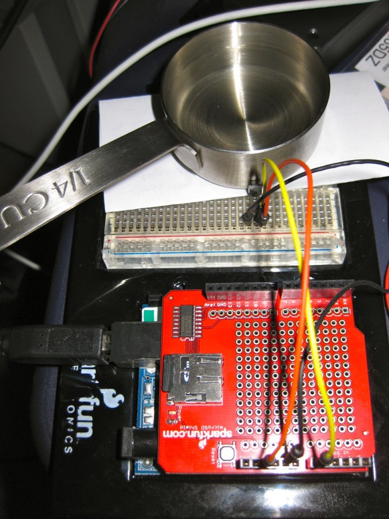
You might just be able to make out the LM35 pressed up against the measuring cup.
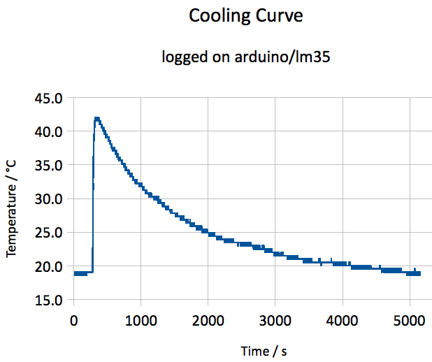
I remember making a right mess of this experiment in my school final Physics practical exam. I also used to do this in my first job when bored testing Campbell CR10 dataloggers, making a nice 1-d cooling curve with a thermocouple and a cup of hot water.

I think the heating came on a couple of times, as there shouldn’t be bumps in the curve. Here’s the data.