Simple ADC with the Raspberry Pi

Raspberry Pi wearing an MCP3008

Hey! This is a really old article. You should really be using gpiozero these days.

I hadn’t realised it, but the The Quite Rubbish Clock did something that a lot of people seem to have trouble with on the Raspberry Pi: communicating using hardware SPI. Perhaps it’s because everything is moving so fast with Raspberry Pi development, tutorials go out of date really quickly. Thankfully, hardware SPI is much easier to understand than the older way of emulation through bit-banging.

SPI is a synchronous serial protocol, so it needs a clock line as well as a data in and data out line. In addition, it has a Chip Enable (CE, or Chip Select, CS) line that is used to choose which SPI device to talk to. The Raspberry Pi has two CE lines (pins 24 and 26) so can talk to two SPI devices at once. It supports a maximum clock rate of 32 MHz, though in practice you’ll be limited to the rate your device supports.

The device I’m testing here is an MCP3008 10-bit Analogue-to-Digital Converter (ADC). These are simple to use, cheap and quite fast converters with 8 input channels. If you hook them up to a 3.3 V supply they will convert a DC voltage varying from 0-3.3 V to a digital reading of 0-1023 (= 210 – 1). Not quite up there in quality for hi-fi audio or precision sensing, but good enough to read from most simple analogue sensors.

The sensor I’m reading is the astonishingly dull LM35DZ temperature sensor. All the cool kids seem to be using TMP36s (as they can read temperatures below freezing without a negative supply voltage). One day I’ll show them all and use a LM135 direct Kelvin sensor, but not yet.

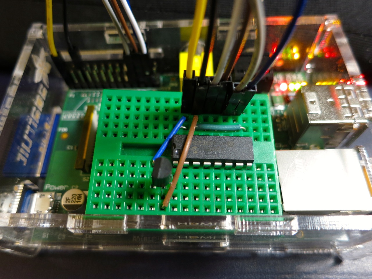
To run this code, install the SPI libraries as before. Now wire up the MCP3008 to the Raspberry Pi like so:

 MCP 3008 Pin          Pi GPIO Pin #    Pi Pin Name
==============        ===============  =============
 16  VDD                 1              3.3 V
 15  VREF                1              3.3 V
 14  AGND                6              GND
 13  CLK                23              GPIO11 SPI0_SCLK
 12  DOUT               21              GPIO09 SPI0_MISO
 11  DIN                19              GPIO10 SPI0_MOSI
 10  CS                 24              GPIO08 CE0
  9  DGND                6              GND

The wiring for the LM35 is very simple:

 LM35 Pin        MCP3008 Pin
==========      =============
 Vs              16 VDD
 Vout             1 CH0
 GND              9 DGND

The code I’m using is a straight lift of Jeremy Blythe’s Raspberry Pi hardware SPI analog inputs using the MCP3008. The clever bit in Jeremy’s code is the readadc() function which reads the relevant length of bits (by writing the same number of bits; SPI’s weird that way) from the SPI bus and converting it to a single 10-bit value.

#!/usr/bin/python
# -*- coding: utf-8 -*-
# mcp3008_lm35.py - read an LM35 on CH0 of an MCP3008 on a Raspberry Pi
# mostly nicked from
#  http://jeremyblythe.blogspot.ca/2012/09/raspberry-pi-hardware-spi-analog-inputs.html

import spidev
import time

spi = spidev.SpiDev()
spi.open(0, 0)

def readadc(adcnum):
# read SPI data from MCP3008 chip, 8 possible adc's (0 thru 7)
    if adcnum > 7 or adcnum < 0:
        return -1
    r = spi.xfer2([1, 8 + adcnum << 4, 0])
    adcout = ((r[1] & 3) << 8) + r[2]
    return adcout

while True:
    value = readadc(0)
    volts = (value * 3.3) / 1024
    temperature = volts / (10.0 / 1000)
    print ("%4d/1023 => %5.3f V => %4.1f °C" % (value, volts,
            temperature))
    time.sleep(0.5)

The slightly awkward code temperature = volts / (10.0 / 1000) is just a simpler way of acknowledging that the LM35DZ puts out 10 mV (= 10/1000, or 0.01) per °C. Well-behaved sensors generally have a linear relationship between what they indicate and what they measure.

If you run the code:

sudo ./mcp3008_lm35.py

you should get something like:

  91/1023 => 0.293 V => 29.3 °C
  93/1023 => 0.300 V => 30.0 °C
  94/1023 => 0.303 V => 30.3 °C
  95/1023 => 0.306 V => 30.6 °C
  96/1023 => 0.309 V => 30.9 °C
  97/1023 => 0.313 V => 31.3 °C
  97/1023 => 0.313 V => 31.3 °C
  98/1023 => 0.316 V => 31.6 °C
  99/1023 => 0.319 V => 31.9 °C
  99/1023 => 0.319 V => 31.9 °C
 100/1023 => 0.322 V => 32.2 °C
 100/1023 => 0.322 V => 32.2 °C
 100/1023 => 0.322 V => 32.2 °C
 101/1023 => 0.325 V => 32.5 °C
 101/1023 => 0.325 V => 32.5 °C
 102/1023 => 0.329 V => 32.9 °C
 102/1023 => 0.329 V => 32.9 °C
 103/1023 => 0.332 V => 33.2 °C

Note that the sensor had been sitting over the Raspberry Pi’s CPU for a while; I don’t keep my house at 29 °C. I made the temperature go up by holding the LM35.

So, you’ve just (fairly cheaply) given your Raspberry Pi 8 analogue input channels, so it can behave much more like a real microcontroller now. I remember from my datalogging days that analogue inputs can be pretty finicky and almost always return a value even if it’s an incorrect one. Check the chip’s datasheet to see if you’re doing it right, and if in doubt, meter it!

qrclock, the demo reel

classy cable for the Quite Rubbish clock

The video of the Quite Rubbish Clock isn’t running the same code that’s in the listing. Here it is, showing off some of the handy code that’s in bgreat’s nokiaSPI Python class:

#!/usr/bin/python
# -*- coding: utf-8 -*-
# qrmovie

import time
# need to use git://github.com/mozillazg/python-qrcode.git
import qrcode
from PIL import Image, ImageFont
import ImageOps
# uses bgreat's SPI code; see
# raspberrypi.org/phpBB3/viewtopic.php?f=32&t=9814&p=262274&hilit=nokia#p261925
import nokiaSPI

noki = nokiaSPI.NokiaSPI()              # create display device
qr = qrcode.QRCode(version=1,           # V.1 QR Code: 21x21 px
error_correction=qrcode.constants.ERROR_CORRECT_M,
box_size=2, border=1)
bg = Image.new('1', (84, 48))           # blank (black) image background

# intro
noki.cls()
noki.led(0)
time.sleep(3)
for i in range(0,769,32):
    noki.led(i)
    time.sleep(0.04)

# display is 14 columns by 8 rows
noki.centre_word(1, 'scruss.com')
noki.centre_word(3, 'presents')
time.sleep(3)
noki.cls()
noki.centre_word(1, 'qrclock')
noki.centre_word(2, 'the')
noki.gotorc(3,3)
noki.text("[Q]uite")
noki.gotorc(4,3)
noki.text("[R]ubbish")
noki.gotorc(5,3)
noki.text(" Clock")
time.sleep(3)

elapsed=0
start_time = time.time()
while (elapsed<12):
    qr.clear()
    newbg = bg.copy()                   # copy blank background
    s = time.strftime('%Y-%m-%d %H:%M:%S')
    qr.add_data(s)                      # make QR Code of YYYY-MM-DD HH:MM:SS
    qr.make()
    qrim = qr.make_image()              # convert qrcode object to PIL image
    qrim = qrim.convert('L')            # make greyscale
    qrim = ImageOps.invert(qrim)        # invert colours: B->W and W->B
    qrim = qrim.convert('1')            # convert back to 1-bit
    newbg.paste(qrim, (18, 0))          # paste QR Code into blank background
    noki.show_image(newbg)              # display code on LCD
    time.sleep(0.4)                     # pause before next display
    elapsed = time.time() - start_time

noki.cls()
noki.centre_word(1, 'for')
noki.centre_word(2, 'more')
noki.centre_word(3, 'details')
time.sleep(3)
noki.cls()
noki.load_bitmap("blogpost-nokia.bmp", True)
time.sleep(7)
noki.cls()
noki.centre_word(3, 'fin')
noki.centre_word(5, 'scruss, 2013')
time.sleep(1)
for i in range(768,-1,-32):
    noki.led(i)
    time.sleep(0.05)
time.sleep(1)
noki.cls()

(This source, plus nokiaSPI class: qrclock-movie.zip)

Lines 43-58 show off the QR clock for a maximum of 12 seconds. Any more, and you’d get really bored.

The screen handling functions I used are:

  • cls() — Clears the screen.
  • led(brightness) — sets the backlight to brightness. For me, full brightness is at 768. A value of zero turns the backlight off. If you don’t have the screen LED connected to one of the Raspberry Pi’s PWM pin, this will either be full on (for any brightness >= 1), or off, for brightness=0. This is used to fade up the screen in lines 24-26, and fade it down far too theatrically in lines 72-74.
  • show_image(PILImage) — display a single bit depth black and white Python Imaging Library object PILImage. This can be no larger than 84×48 pixels.
  • load_bitmap(file, Invert) — load a single bit depth black and white BMP file of maximum size 48×84. If Invert is true, keep the colours as they are, otherwise swap black and white to make a negative image. nokiSPI flips images by 90°, so the image I loaded to show the URL of the blog post looks like this:
    blogpost-nokia
    (I know, I could have generated this in code, but I’d already made the image using qrencode. I couldn’t be bothered working out the image size and offsets.)

The text handling functions I used are:

  • gotorc(row, column) — move the text cursor to row, column. The screen only has 14 columns by 8 rows if you use the standard 6×6 pixel font, so keep your text short to avoid disappointment.
  • text(text) — write text at the current cursor position.
  • centre_word(row, text) — write text centred in row row. Since the text rows are a maximum of 14 columns, text with an odd number of characters will appear slightly off-centre.

There are many more functions in the nokiaSPI class; watch the demo, have a dig through the source and see what you can use.

The Quite Rubbish Clock

Hey! This article is really old and probably doesn’t work any more: things have changed a lot in Raspberry Pi world since 2013

Update 3: code for the demo video is here.

Update 2: In which I actually post working code.

Update: Eep! This post was featured on the Raspberry Pi blog today. Thanks, Liz!

And now for something completely different:

… a clock that isn’t human readable. You’ll need a QR code reader to be able to tell the time.

Nokia screen on Raspberry Pi

This, however, is not the prime purpose of the exercise. I was looking for an excuse to try some direct hardware projects with the GPIO, and I remembered I had a couple of Nokia-style surplus LCDs lying about that could be pressed into service. These LCDs aren’t great: 84×48 pixels, 3V3 logic, driven by SPI via an 8-pin header which includes PWM-controllable LED backlighting. They are cheap, and available almost everywhere: DealExtreme ($5.36), SparkFun ($9.95), Adafruit ($10, but includes a level shifter, which you really need if you’re using a 5V logic Arduino), Solarbotics ($10) and Creatron (about $12; but you can walk right in and buy one). Despite being quite difficult to use, helpful people have written drivers to make these behave like tiny dot-addressable screens.

I’d been following the discussion on the Raspberry Pi forum about driving the Nokia LCD from a Raspberry Pi. Only when user bgreat posted some compact code that was supposed to run really fast did I dig out the LCD board and jumper wires. Building on bgreat’s nokiaSPI.py class and a few other bits of code, here’s what I built to make this singularly pointless clock:

#!/usr/bin/python
# -*- coding: utf-8 -*-
# qrclock - The Quite Rubbish Clock for Raspberry Pi - scruss, 2013-01-19

import time
# need to use git://github.com/mozillazg/python-qrcode.git
import qrcode
from PIL import Image
import ImageOps
# uses bgreat's SPI code; see
# raspberrypi.org/phpBB3/viewtopic.php?f=32&amp;amp;amp;amp;t=9814&amp;amp;amp;amp;p=262274&amp;amp;amp;amp;hilit=nokia#p261925
import nokiaSPI

noki = nokiaSPI.NokiaSPI()              # create display device
qr = qrcode.QRCode(version=1,           # V.1 QR Code: 21x21 px
                   error_correction=qrcode.constants.ERROR_CORRECT_M,
                   box_size=2, border=1)
bg = Image.new('1', (84, 48))           # blank (black) image background

while 1:
    qr.clear()
    newbg = bg.copy()                   # copy blank background
    s = time.strftime('%Y-%m-%d %H:%M:%S')
    qr.add_data(s)                      # make QR Code of YYYY-MM-DD HH:MM:SS
    qr.make()
    qrim = qr.make_image()              # convert qrcode object to PIL image
    qrim = qrim.convert('L')            # make greyscale
    qrim = ImageOps.invert(qrim)        # invert colours: B-&amp;amp;amp;gt;W and W-&amp;amp;amp;gt;B
    qrim = qrim.convert('1')            # convert back to 1-bit
    newbg.paste(qrim, (18, 0))          # paste QR Code into blank background
    noki.show_image(newbg)              # display code on LCD
    time.sleep(0.4)                     # pause before next display

(Convenient archive of all the source: qrclock2.zip, really including bgreat’s nokiaSPI class this time …)

To get all this working on your Raspberry Pi, there’s a fair amount of configuration. The best references are bgreat’s own comments in the thread, but I’ve tried to include everything here.

Enabling the SPI kernel module

As root, edit the kernel module blacklist file:

sudo vi /etc/modprobe.d/raspi-blacklist.conf

Comment out the spi-bcm2708 line so it looks like this:

#blacklist spi-bcm2708

Save the file so that the module will load on future reboots. To enable the module now, enter:

sudo modprobe spi-bcm2708

Now, if you run the lsmod command, you should see something like:

Module                  Size  Used by
spi_bcm2708             4421  0

Installing the WiringPi, SPI and other required packages

WiringPi by Gordon is one of the neater Raspberry Pi-specific modules, as it allows relatively easy access to the Raspberry Pi’s GPIO pins. For Raspbian, there are a few other imaging libraries and package management tools you’ll need to install here:

sudo apt-get install python-imaging python-imaging-tk python-pip python-dev git
sudo pip install spidev
sudo pip install wiringpi

Installing the Python QR code library

Finding a library that provided all the right functions was the hardest part here. I ended up using mozillazg‘s fork of lincolnloop‘s python-qrcode module. mozillazg’s fork lets you use most of the lovely PIL methods, while the original hides most of them. Since I had to do some image compositing and colour remapping to make the image appear correct on the Nokia screen, the new fork was very helpful.

To install it:

git clone git://github.com/mozillazg/python-qrcode.git
cd python-qrcode/
sudo python ./setup.py install

The tiny 84×48 resolution of the Nokia screen doesn’t give you many options for sizing QR codes. For the time display of the clock, a 21×21 module Version 1 code with two pixels per module and one module margin just fits into 48 pixels. Using a medium level of error correction, you can fit the 19-character message (such as “2013-01-19 18:56:59”) into this tiny screen with a very good chance of it being read by any QR code reader.

(In the video, there’s a much larger QR code that’s a link to this blog post. That’s a Version 7 code [45×45 modules] at one pixel per module and no margin. This doesn’t meet Denso Wave’s readability guidelines, but the Nokia screen has large blank margins which seem to help. It won’t read on every phone, but you’re here at this link now, so you don’t need it …)

Wiring it all up

(Do I really need to say that you’ll be messing around with the inner delicate bits of your Raspberry Pi here, and if you do something wrong, you could end up with a dead Raspberry Pi? No? Okay. Just make sure you take some static precautions and you really should have the thing shut down and powered off.)

You’ll need 8 female-female right-angled ones). Note that the thick border of the LCD is the top of the screen. These boards are made who-knows-where by who-knows-whom, and there’s a huge variety of labels and layouts on the pins. My one appears to be yet another variant, and is labelled:

  1. VCC
  2. GND
  3. SCE
  4. RST
  5. D/C
  6. DNK(MOSI)
  7. SCLK
  8. LED
screen labels

This is how I wired it (from comments in bgreat’s code and the GPIO reference):

 LCD Pin       Function      Pi GPIO Pin #   Pi Pin Name
============= ============= =============== =============
 1 VCC         Vcc            1              3.3 V
 2 GND         Ground        25              GND
 3 SCE         Chip Enable   24              GPIO08 SPI0_CE0_N
 4 RST         Reset         11              GPIO17
 5 D/C         Data/Command  15              GPIO22
 6 DNK(MOSI)   Data In       19              GPIO10 SPI0_MOSI
 7 SCLK        Serial Clock  23              GPIO11 SPI0_SCLK
 8 LED         Backlight     12              GPIO18 PWM0
GPIO wiring
back of screen

Wire it up, and fire up the program:

sudo ./qrclock.py

Yes, code that accesses GPIO needs to be run as root. Pesky, but helps you avoid running code that accidentally scrams the nuclear power station you’re controlling from your Raspberry Pi …