Blueline / Black & Decker Power Monitor RF Packets

Update 2014-10-02: I’ve forked Bryan’s Arduino code and added some instructions: scruss/Powermon433 (though use Bryan’s, srsly)

Update 2014-08-19: Bryan Mayland has decoded the data on Arduino! More details here: CapnBry/Powermon433

Given that I first started thinking about reverse-engineering the Blueline Powercost Monitor‘s data stream in September 2010, I hardly win any awards for rapid development. Here’s what I know so far about the device and its transmissions:

  • The Blueline unit and the (now discontinued) Black & Decker Power Monitor (EM100B) appear to be functionally identical. Both transmit data using simple ASK/OOK at 433.92 MHz in the ISM band.
  • It is, however, completely different from the Norgo NGE101 meter, dammit.
  • The display unit is made by Hideki Electronic Limited, who make many small weather stations and wireless displays. [Pictures of the display circuit boards]
    Inside a Black & Decker Power Meter
  • The transmitter unit was designed by Intectus in Ottawa for Blueline. It uses a TI MSP430 µcontroller. [Transmitter board picture]
    Black & Decker Power Monitor: Meter Transmitter board
  • The transmitter can be triggered by simulating a power meter if you flash a 940 nm IR Emitter LED for 50 ms into its sensor. 1× 50 ms flash represents 1 Wh of power consumed. A pulse frequency of 1 Hz represents 3.6 kW consumption.
    Arduino-based domestic power meter simulator
  • The transmitter sends a bundle of three (seemingly) identical packets every 31.8 seconds. These appear to contain consumption data, as the display updates approximately every 32 seconds.
    a data packet bundle
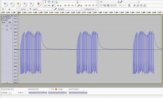
  • A series of contiguous packets, recorded as audio using a simple circuit described by the Protocol Analyzer project: audio201311182215-silenced (FLAC; please note that interstitial silences have been blanked to reduce file size).
  • Temperature packets may be sent separately from power, as the display updates temperature much more slowly than power use.
  • Power packets only appear to contain use data (along with a transmitter ID). If the sensor receives an absolutely constant input, the packets transmitted 32 s apart can be identical.
    powermeter-203453vs203525
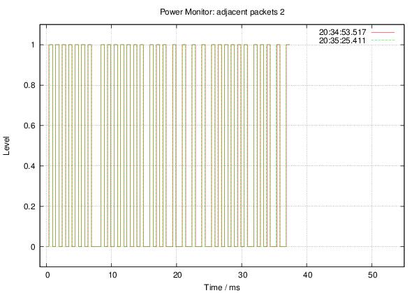
  • The packets appear to be Manchester-encoded.

Some rough notes on mark/space timing (all times in µs):

Mark : Mean    529.4 Min    499.0 Max    590.0 StdDev:   15.03 
Space: Mean    694.5 Min    385.0 Max   1474.0 StdDev:  281.57

Mark/space times, by frequency (all times in µs):

MARK
====

          µS
Rank     Value   Count
-------- ------- -----
     1         522  498
     2         544  206
     3         567   32
     4         499   32
     5         590    8

SPACE
=====

          µS
Rank     Value   Count
-------- ------- -----
     1         476  279
     2         975  223
     3         454   99
     4         952   65
     5         431   26
     6        1474   22
     7         408   21
     8         499   17
     9         998   12
    10      199000    8
    11         385    2
    12        1451    2

More later, including raw packet data.

Thanks to Randy Simons and Bryan Mayland for the recent help. Thanks too to Brett “Wiring” Hagman for asking just why I was trying to do this …

52 comments

  1. I’ve looked at almost everything I can lay my hands on. It’s no problem reading the signal, but the protocol’s a weird one.

  2. I just ordered one of these so I’m motivated to help demodulate this signal! Mine should arrive in a week.

    I downloaded your flac file and looked at the waveform. You say that the waveform is Manchester coded but to me it looks like it’s a sort of pulse width modulation. The ‘on’ times all look the same but the ‘off’ times look like they’re modulated to represent ones and zeros. If analyzed this way, the first packet in your data set looks like ‘0000 0001 0000 0010 0111 1100 0001 0011’. Of course all the ones and zeros could be backwards.

    Do you have the receiver unit’s readout for each of these data packets? That would help try to understand the data stream.

  3. Yeah, I think my signal’s inverted. Also, the transmitter inside the meter unit is pretty much hard-coded to Manchester as a protocol, so I doubt it can be much else.

  4. Hmm, I don’t think Manchester can have a constant ‘on’ time like this signal. Manchester should have 2 ‘on’ durations and 2 ‘off’ durations. Looks like a fixed ‘on’ time, variable ‘off’ time PWM modulation to me.

  5. I think I’ve got most of this protocol figured out. I got a RTL2832 based DVB dongle to receive the packets. I used https://github.com/merbanan/rtl_433 to demodulate the packets and pointed a webcam armed with http://www.unix-ag.uni-kl.de/~auerswal/ssocr/ to record the display.

    The FCC filings describe the bit protocol:
    https://apps.fcc.gov/eas/GetApplicationAttachment.html?id=711409

    “Data obtained by an IR-reader/sensor is transmitted in form of short bursts every 28.5 to 31.5 seconds on 433.92 MHz (single frequency) . The carier is On/Off pulse modulated (logic ‘1’: O.5ms TX-on followed by 2ms TX-off. logic ‘O’: O.5ms TX- on followed by 4ms TX-off).

    Some nomenclature on the bit sequence. Every 30 seconds there are 33 * 3 bursts of rf power. Lets call these 33*3 bursts a ‘packet’. Each packet contains 3 ‘frames’. Each frame contains 4 bytes. The first byte is always a leading header of 0xfe. The second and third bytes are the data of the frame and the fourth byte is the CRC over the second and third bytes (sometimes offset, see below).

    When the unit is first powered up it transmits a ‘Transmitter ID’ with 0xfe header and CRC. Pressing the button on the transmitter causes it to retransmit this ID. Holding the button for 10 seconds causes it to change it’s ID.

    The two data bytes, between the 0xfe header and the CRC are ‘offset’ by the transmitter id. There seems to be an ‘off-by-one’ error in the msb as the data bytes cross above the transmitter ID probably because of the way the microcontroller is doing it’s math.

    The CRC is used is CRC-8-ATM with polynomial 100000111. This is calculated across the data bytes after the offset by transmitter ID except in a transmitter ID packet. This ensures different meters can coexist.

    The first 2 frames are always equal to each other and may be the same or different than the 3rd frame. There are 3 types of packets that I’ve identified in addition to the transmitter id packet.

    The first is ‘power’ packet. This packet can be identified because the least significant 2 bits of the 1st data bytes in frame 1 and 2 are ’01’ or ’10’. The second data byte contains the MSB and the first data byte contains the LSB (including the least sig 2 bits – not sure about this). The 3rd frame is of the same format as the first 2 frames but can have different data! Maybe the meter gets new data between the first 2 and last frame. In this case the hand held display uses the one of the first 2 framess. To convert from this ‘count’ to kilowatts, take 3600/count * your meter’s Kh value (7.2 on my meter). This packet is repeated 4 times at approx 30 second intervals.

    The second is the ‘temperature’ packet. This packet can be identified because the least significant 2 bits of the 1st data bytes in frame 1 and 2 are ’11’. The second data byte contains the temp data. I’m guessing this is 2’s complement, but haven’t gone through enough temp range to verify. The first byte contains unknown flags. I know low battery is in here but not sure where yet. The 3rd frame is a power frame with decoding the same as in the power packet. To decode temp take 0.75*temp byte -19 to get to Fahrenheit or similar for Celsius. This packet comes 5th after 4 power packets.

    The third type of packet is the ‘energy’ packet. This packet can be identified because the least significant 2 bits of the 1st data bytes in frame 1 and 2 are ’00’. The second data byte contains the MSB and the first data byte contains the LSB (excluding the least sig 2 bits – 14 bits total ). The 3rd frame is a power frame with decoding the same as in the power packet. To decode power take 0.004*energy value * your meter’s Kh value (7.2 on my meter) to get to kWh. This packet comes 6th after the temperature packet. Then the cycle restarts with power packets.

    I’ve forked the rtl_433 project to https://github.com/radredgreen/rtl_433 with code to demodulate the protocol. I’m still testing and polishing things up a bit. I’ve contacted https://github.com/merbanan/rtl_433 and have requested that he merge my changes back into his repo.

    Please let me know if you find any improvements to the demodulation.

    Thanks!
    Red Green

  6. Red Green, can I just say ‘wow’? I don’t know how many hours I’ve dumped into trying to decode this protocol without arriving at a result and you’ve gone and done it.

    I had gotten all the way to: finding the frequency, augmenting rtl433, short/long keying, 32 bits in a frame, 2 usually the same then a third that was different on a fixed period. I could not figure out how when my power usage was the same every transmit that 3 of the bytes would be different each transmit. I knew there had to be some sort of tramsitter ID in there too, but just couldn’t put it together.

    I have a Black and Decker EM100B, but inside the PCBs are silkscreened ‘blueline’. It transmits on 433.845 MHz and parses with short=128+64, long=384+64, reset=20000. My pulses are almost exactly right on 128/384 samples. The EM100B has a kw scale of 1.0 compared to your 7.2. All my packets don’t require the +1 to the first byte (VALID-).

    Two things about your 433 tree:
    1 – You’ve removed the getopt options for a few things, options ‘t’ ‘a’ and ‘m’. m is supposed to have a parameter and D isn’t.
    2 – I believe there’s an error on https://github.com/radredgreen/rtl_433/blob/master/src/rtl_433.c#L522 where it references packet[3] and there are only 3 packets. With that switched to packet[2], my data perfectly matches up to the receiving unit for all 3 classes of packets (well, 4 if you count the ID packet).

    I’m not sure the “Energy” reading matches up, because sometimes it goes down, but I am super stoked about being able to pump this into my emoncms. It is so coincidental that you showed up, just Friday night I was considering buying some current clamps to build an EmonTx, now I don’t need one!

    If you want to get in touch with me , I am bmayland leoninedev.com.

  7. Bryan,

    I must have removed the ‘t’, ‘a’, ‘m’ options with accidental edits. I’ll have to fix that.

    Good catch with “packet[2]”.

    I actually have the Black and Decker unit too. My meter is the mechanical style with a Kh value of 7.2. I program that into the handheld display unit.

    I too noticed the Energy readouts occasionally decrease today. When I posted the code yesterday I hadn’t yet seen this bug. If you can figure out what’s going on, it would be much appreciated.

    I only saw the VALID+ with one Transmitter ID = 0x9054 and not any others, so be on the watch for something weird going on here… one example I have of a VALID+ frame is 0xfe0ec82a.

    This was a fun puzzle. The thing that broke it open for me was that I noticed that (what we now know is) the power packet would repeat the same value if the monitor was off the meter and given no input – IR or motion. So 4 of the 6 packets would be identical and I named them the ‘zero packet’. Then I noticed that when the ID was reset with a 10 sec button press, the zero packet would change when the ID changed. I did this 10 times recording the zero packet and the id packet and noticed that difference (would have expected XOR) between the id and the zero packet was always the same = 0x0300** where ** changed. I suspected the ** as a CRC.

    While doing this experiment I noticed that the un-offset zero packet always had a 0x0e 4th byte. This led me to believe the CRC was calculated on the un-offset data bytes — which would help with monitor coexistence.

    The other stroke of luck was searching for “8 bit CRC” and finding the Computation_of_cyclic_redundancy_checks page on Wikipedia. The first example is “CRC-8-ATM”. I tried it with http://ghsi.de/CRC/index.php?Polynom=100000111
    and it immediately worked on the ID packet. A little more trial and error and I found the first byte sometimes needs to be incremented in the other types of packets to get a clean CRC.

    After I knew i was looking at the raw data bytes, I connected the monitor to my power meter, rigged up SSOCR, pointed my webcam at the handheld display and collected about 24 hours worth of data. Then I worked on correlating the data on the display to the data in the packets.

    I’ve emailed Blueline asking if they could verify the constants and check the various +1’s, but I don’t expect much of a response. I appreciate anyone checking those more thoroughly.

    I’ve also contacted Benjamin Larsson and he’s willing to merge the changes back into rtl_433 once we’ve got things settled. Let me know if you find any other improvements and we can submit them all together.

    Sometimes handy…
    Red Green

  8. There’s definitely something still not 100% right because my “total kwh” packet is now only passing CRC when it gets the 1 added to the first byte (ID=8845).
    fe b709 3f
    INVALID- packet 0x2EC43F
    fe 430a 8a
    INVALID- packet 0xBAC48A

    It started when the second data byte rolled to 0x00, and I suspect it will stop when it rolls to 0x10. The problem is if you add 1 to the first data byte to make it pass the CRC, it shifts from being a “total kwh” (type 3) to a “temperature” packet (type 0) and the value is then incorrect. I thought it might be due to that nibble being a 0, but it doesn’t seem to have a problem with other nibbles being 0.
    fe 06e0 bb
    VALID- packet 0x7E9ABB
    fe 06f5 30
    VALID- packet 0x7EAF30

  9. Got it, I finally figured it out when my checksums started working as the second data byte passed 0x45 (ID=8845) . What it actually is is that the packet is actually:
    struct {
    uint8_t preamble;
    uint16_t val;
    uint8_t crc;
    }
    Where val is little endian. The transmitter id is then a straight unsigned 16 bit subtraction on val. There’s then no need to do any comparisons or off by one additions. The packet types are 0x00, 0x01 are current data, then 0x02 temperature, and 0x03 total.

    This also cleans up a lot of the bitmath shifting the values around because val is the value you want. Anyway, I’ll clean up all my debugging code and post a pull request so you can give it a try.

  10. Just posted a new version to github. I believe this to be much better. Give it a try and let me know if you see anymore decreases in kWh values.

  11. You beat me to it before I could even fork this morning! Working great so far with all packets. I had to reset the transmitter last night because after had my epiphany and had it parsing all packets, I started getting “54w usage” and even the receiver was reporting 0.0w. The new code looks a lot simpler too! I’ll let it run and keep an eye on it. If I don’t report back then everything is perfect.

    I believe you’re also right about the “low batt” bit. I put some discharged nicad batteries in my transmitter and that 0x20 bit was set (receiver indicated low batt).

  12. Bryan, looks like our comments posted at the same time and we realized that the data is little endian concurrently. Have a look at what I posted and see if what we have is equivalent.

  13. Forgot about this nugget. What do you think about the temperature being in 0.5C units with a 40C offset? For some reason 40C offsets seem to be all the rage on wireless transmitters.
    tempC = (recvd_temp / 2.0) – 40.0

    This correlates closely with your slope-intercept constants and seems more straightforward.

  14. I put the unit in my freezer and got down to a count of 36 which the display reported as 1F (-17.2C). I’ve only taken the unit up to a count of 132 which the display reported as 80F (26.7C). If we use 0.5*count-40, the 36 count would be reported as 22C or more than 5C off. This doesn’t seem right although up there in Canada you probably know more about this part of the temp scale than me : )

    I will say that as the temp was decreasing in my freezer, the count didn’t seem to move linearly with the display on the unit so the response may not be linear.

    It would be fun to create an artificial transmitter to send each count to the display to see it’s reported value and create a plot of reported temp (C and F) vs count. Does any one have an easy way of transmitting artificial packets at 433.92 MHz?

    There is no dedicated temperature IC on the board, so it must be using the microcontroller’s ADC and bandgap reference to determine temperature. I looked at the data sheet at http://www.ti.com/lit/ds/symlink/msp430f1122.pdf to see if it is just sending out the raw data reported by the ADC but I couldn’t find a chart relating temperature to count. Maybe you’ll have more luck. At any rate, this microcontroller is probably not too accurate at measuring temperature so I wouldn’t use this temp reading for anything too serious, but it would be nice to get the decoding to match the display.

    I also found the low battery bit which is in the new github post. I wonder what the other unknown_bits are for. Again an artificial transmitter could help here.

    What are you all planning to do with this code when it’s finished?

  15. Yeah you’re right about the temperature. I can’t believe it isn’t a more simple calculation but they do start to diverge from what’s on the display as the temperature gets lower. Your constants matched up every time.

    I’ve ordered some 433.92Mhz OOK transceivers which should be here next week so I can run a full sweep assuming they work. My rtl usually shows a frequency deviation of 50 ppm which puts the frequency I’m seeing at around 433.840– a pretty good distance from 433.920. I’m hoping my rtlsdr is just wonky.

    What I’m planning to do with the code is just code a microcontroller with it and V-USB and make a little USB receiver dongle to pipe the data into emoncms. It’s just for my own information and I’m hoping to some day be able to look at the data and say “Now getting solar panels is feasable”.

    Power Usage

  16. Wow redgreen, very impressive work. As some others here, I also managed to get to the point of reading raw transmitted binary packets correctly, but was stuck at decoding the protocol – and I have some successful experience with that for a number of other devices. I had it easier even – there is a device that BlueLine sells, that receives 433Mhz sensor transmission and provides TCP/IP gate interface for readouts (so there was no need for OCR for me). But I think this also misled me, as I could see reported data every 30 seconds, and all of it at the same time (so instantaneous, total, signal strength, low battery, temperature). So I thought that all of this is being transmitted every 30 secs, and differences in triplets are due to my radio receiver decoding weak RF signal incorrectly. So well done!

    I need to try your github code ASAP. Thanks again!

  17. I see you’ve also figured out that the instantaneous power usage packets are only type 1. I received my 433mhz ASK transceiver modules and I haven’t had any luck yet with the decoding side. I thing my receiver is too far away because even the Black and Decker device can’t get a signal where I do the development.

    I did get a good mockup of the transmitter going, however the kwh total packet doesn’t seem to properly update the display. The code is so simple that with serial commands to change values and debugging information the whole thing is 4kb.

    The packet timings are 0.5ms on then 0.5 off for 1, or 1.0ms off for 0. After the first 8 bits (0xfe) there is an additional 0.5ms OFF period before the data starts. At the end of the packet there is an additional 0.5ms ON period to close the last bit.

    The temperature is non-linear and appears to follow the curve for an NTC thermistor so the value is some sort of shifted ADC reading. It is fairly linear between the 30F-90F range.

  18. Hey Bryan, I have at least one spare Black & Decker unit you can cannibalize for a test rig …

  19. Hmm, GitHub code didn’t work for me out of the box – received data fails CRC test, so all is discarded. I have a BlueLine (not B&D) unit, can that make a difference (don’t think so)? Any ideas before I dive into debugging?

    Thanks!

  20. It’s been a while but I’ve been working on this still. I had really terrible luck with the superregenerative type receivers that you can get off ebay for like $2 a piece. The transmitter in the power monitor just isn’t all that powerful and even a few meters away you can’t even see any part of the signal recognizable in the noise. I can my own 433MHz transmitter and get it to be picked up by but the RTL-SDR and the superregenerative receiver but picking up the power monitor was a no go. I’ve even bought another set of receivers from another vendor to make sure that the first batch wasn’t just worthless.

    From there I moved on to a superheterodyne receiver. These work pretty well. I haven’t done a range test or anything though so I can’t say how well exactly. The problem is that these receivers run on the order of $9 each, which is kinda more than I’d want to pay for a cheap receiver solution (when you can get a whole RTLSDR for $25).

    I’ve got some RFM69HW modules coming which apparently can aparently also be set to an OOK signal mode with various level trigger and decay settings. I can get them for $4 each, which seems about right. They’re also a lot more general purpose, have an SPI interface, and can do a lot more if you want to for example re-broadcast the packets to other nodes.

  21. I’ve posted my Arduino / ATmega code to github
    https://github.com/CapnBry/Powermon433

    It should support both pin-wiggler receivers like superheterodyne and superregenerative types, although the latter I haven’t had much success with. It also can use an RFM69W module which can be had for $3.60 off eBay user anarduino. Any of the RFM69* modules work, but DIO2 output must be run to the ATmega.

    I played around with reducing the receiver bandwidth down to 1.3kHz and scrubbing around the frequency until I got reception and ended up at 433.845MHz. The code in github currently allows 50kHz bandwidth to account for transmitter deviation, but even at 100 or 200kHz the sensitivity isn’t terribly impaired. I couldn’t get the FEI or AFC blocks to work. They might just work on FSK data.

    Note that the code is tied to my transmitter ID, it should store it in eeprom but I’ll get to that at some day. It does switch transmitter IDs if it sees a new ID (untested).

  22. Has anyone been successful in running this code on a Nano? I have the code running on an Uno but was thinking of shrinking things for a final installation. However, when I hook up my RF module (superheterodyne 3400RF clone), I don’t get any activity. I believe there must be something going on with the implementation of interrupts since a simple attachInterrupt works fine.

  23. I grabbed the Powermon433 code from GitHub and strippted out the RF69 code, and any TX code. I have it dumping binary of the packets received. It is consistently failing the CRC8 check. Any ideas?

    I get 3 transmissions in a group that are the same, so I assume I’m getting the right data (the format below is each of the 3 bytes in BIN and the result of CRC8 in BIN):

    raw: {10001001 011 10001101 10100100}
    CRC ERR
    raw: {10001001 011 10001101 10100100}
    CRC ERR
    raw: {10001001 011 10001101 10100100}
    CRC ERR
    [2336074] No data

  24. Well, derp. In my defence I grabbed CapnBry’s code. Also, I ran the output of the superregen (bad I know) through an simple single transistor NOT gate to invert the logic. It’s working now!

    (Well, except that the code says the temperature is 34, but the commercial receiver is showing 0C (which should be 32F)).

  25. No worries, Alex; it happens. Glad you got a super-regen receiver to work, as I don’t think I did. Bryan’s code is better, so best to use his, even if the output data format is a bit odd and the temperature is in °F, those quaint little units they use down south.

    Temperature reporting is at best directionally correct on these devices. There’s no separate sensor, so it’s using the internal temperature sensor built into the µc inside. Also, meter boxes tend to be quite exposed, and my sensor gets a good +10°C of solar gain when the sun rounds the corner of the house.

    My biggest problem right now, though, is my readings being wildly off for no good reason. I’m getting 39 kW displayed sometimes.

  26. I find the temperature acceptably close to the actual outdoor temperature. In my case, the unit is installed on the north side of my house which is mostly in the shade and avoids the majority of the harsh weather. I see that the commercial unit is within 1-2 degF of my weatherstation which seems good enough.

    My biggest issue is trying to get the kW and kWh data to compare to the numbers on the face that I have been manually recording for ages. I should be able to multiply those by a factor and apply an offset and have it match the BlueLine data, but for the life of me I can’t figure it out!

  27. To get the W to match the display kW (W*1000), I added my meter’s power factor (7.2) to this chunk of code (I’m not going to /1000 as that loses some precision that I like to see):

    case OOK_PACKET_INSTANT:
    // val16 is the number of milliseconds between blinks
    // Each blink is one watt hour consumed
    g_RxWatts = (3600000UL / val16) * 7.2;
    break;

    As for the temperature, I’m working on a best fit formula to replace the tables of observations and estimations. Plotting them in a spreadsheet, I observed that the first few values appear to be guess/estimations – they don’t fit the line. Removing them and adding a couple of my own observations, and switching the values to C, I’m currently looking at

    Tc = 0.445 * x – 31.222

    My next challenge is to undo the Arduino upgrade I did last night. The code won’t compile in 1.6.6 (lots of fussing about statics being previously declared as externs). Grrr. Oh, and why did I got 1.6.6 – was hoping the serial monitor would dump/save/write to a file. It doesn’t. Bleah.

  28. g_RxWatts = 3600000UL / val16 * Kh;

    g_RxWattHours = 0.04 * val16 * Kh;

    I found some code that suggested 0.04 needed to be factored in for the WattHour calculation but I can’t find that reference now.

    I calculated my Kh as 29.2 but the power company uses a multiplier of 40 (as written on the meter). I don’t know if the issue I’m seeing is the power company overcharging me or my calculation being incorrect. Either way, the numbers don’t line up no matter what I use as a multiplier/Kh. It’s my understanding that if I use the code above with the correct Kh, the resulting W and Wh values should be correct. If so, I can concentrate on getting the correct multiplier on the number wheels to get those to Wh as well.

  29. My Geetech superheterodyne receiver arrived yesterday. Unbelievable difference! Pin compatible with SparkFun’s super-regenerative board and only $2 more (well actually, since shipping from dx.com is “free”, it actually cost less in the end).

    Previously I would receive about 90% of transmissions under normal conditions, and less than 10% when running my 3D printer.

    Now I have the unit sitting practically beside the printer and I’m receiving 99% of the transmissions!

  30. I have quite a few receivers that I collected for this project. I didn’t know what I was looking at initially so I purchased several superregenerative modules. I tried them and they did not function at all (well, they might have worked but the range was so short I saw nothing from the meter when coding). I later purchased several types of superheterodyne modules. The first were 3v3 which did not work with my UNO or the Nano’s I was planning on using, so I bought some Arduino Pro modules. These were hard to work with as they required serial modules. Logic level changes didn’t work for me, so I was down to a single module that functioned on an UNO.

    Long story short, I ended up using the only module I had that would work at reasonable range. My code is a little more complex as it uses PowerMon433 as well as 2 Acurite sensor codes to receive simultaneously. But, it has issues reading all data and tends to lose the other sourses. I think it’s a range issue, so now I’m going to have to get a new wireless module I think. sigh…

  31. I’m still confused why radredgreen uses a factor on his TotalEnergy packet and neither this or CpnBry’s code does. I have been working with matching my data to my meter’s numbers and think there is an issue related to this factor (0.004) though I don’t know what the correct code SHOULD be. Perhaps there was something specific about radredgreen’s meter that required this factor for him?

  32. 16bit limts…

    I’ve been trying to see how low I can get my power usage. My graphing tool (rrdtool) seems to be hitting a floor of 388W.

    My utility meter has a power factor of 7.2, and the monitor counts milliseconds between pulses. So:

    W = (3,600,000 / count) * 7.2

    See the problem?

    If count is a uint_16_t, it will max out at 65,535 which means the lowest W I’ll see is 395. Except that 16 bit math does:

    3,600,000 / 65,535 = 54
    54 * 7.2 = 388

    So, I’m a bit more motivated to wait for and parse out the WH number….

  33. I figured out what I should be using. In my case, the Kh is actually 0.6 and there is a multiplier of 40 so I need to use a Kh equivalent of 24. I think 0.004 is 4/1000 so his Kh was 4 and he divided by 1000 to get kW and kWh. Just a guess but that’s all I can figure.

    The really annoying thing here is that I spoke to my utility 2-3 times over the last 2 years trying to figure out what my kH should be and it wasn’t until last month that someone actually listened to the request and gave useful info. Previously they simply stated “7.2 is standard”. However, I don’t have a standard setup. My home has it’s own vault and a dual 200A panel setup so they had to use a non-standard metering setup. Would have been nice if they simply looked at my account and given the real info on day 1…

  34. A suggestion: I changed the Watt hours variable from 16 to 32 bit:

    static uint32_t g_RxWattHours;

    and made a note in my comments about when it will roll over:

    case OOK_PACKET_TOTAL:
    // The meter’s WattHours is a cummulative (16bit) counter. It will roll over at 65,535
    // The power factor (7.2 for me) means the output will roll over at 471,852 Wh
    // (32 bit = 4294967295)
    g_RxWattHours = val16 * POWER_FACTOR;
    break;

    My interest (at the moment) is total Wh consumed in an hour, so my perl script that logs the data from the Arduino will watch for the roll over.

  35. My service is capable of high current, but I don’t draw all that much. The last rollover was 1/27. The value resets at 65536 and is currently at 52304. So, in the winter, it resets every 24 days. In the summer when the heat is off I hardly use any power (less than 1/4 right now). Peak I draw more, but I’d say rolling over once a month isn’t that big a problem.

  36. Oh, I should point out that I don’t apply the Kh (24) on the Arduino code as that would require a larger variable storage type. I am currently outputting the base value but eventually will change the code so that when I output it to MQTT it will be multiplied.

  37. I am also finding that the 0.004 multiplier on kWh is not correct for my setup. My Kh is 1.0, but the kWh output from https://github.com/radredgreen/rtl_433 is about 14.8% higher than the Digital Display is showing.
    Did anyone figure out the correct multiplier?
    Or, does anyone know what the units of the energy count actually are?

  38. It doesn’t have any units — it’s just a conversion from pulse counts to KWh. It all depends on the meter’s Kh value, which it seems is not always accurately recorded.

  39. My meter has the infrared pulse output, which pulses once for every Watt-hour consumed (Kh = 1.0). So, I would assume that the units of the energy count would be Watt-hours (one count for every pulse). If so, then the multiplier should be 0.001 (kW/W). But, for my setup, 0.0035 seems to work best.

    I understand that different meters have Kh values that are not accurately recorded, but I’m not getting how the 0.004 multiplier was ever calculated. Do you think it was empirically determined?

  40. The author hasn’t been around here for a while. Why not drop an issue in their git repo and see what they say about it?

    The arduino code doesn’t work this way, and I’ve only ever been interested in the (totalled, integer) pulse counts to avoid other people’s assumptions and rounding errors.

Leave a comment

Your email address will not be published. Required fields are marked *