I like old (as in 68K old) Apple Macintoshes, but I don’t like their hard drives. Apple used SCSI drives, which were super-cool at the time (multiple drives on one bus! extra devices like SCSI scanners, too!) but now seem an absolute pain. There may be a lot to complain about with USB storage, but compared to SCSI, it just works.
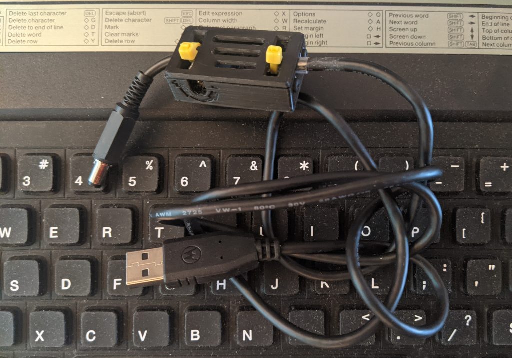
While the 40 MB Quantum SCSI drive in my Mac Classic II still works, it gets really full really fast and that old spinning rust won’t spin forever. One of the newer ways to replace a SCSI drive is the BlueSCSI, an open-everything design based on a cheap Blue Pill micro-controller board, a Micro-SD card slot and some passive components. The whole kit is very affordable, and a local maker sells them, so it was worth a try.
I’ve had nothing but miserable failure with Blue Pill boards, and very quickly moved on to STM32F4 board that actually work. It didn’t fill me with much hope that the board I got with my kit looked like this, end on:
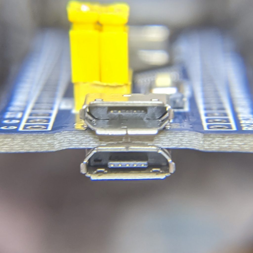
There are two of ____.
Despite that oddness, it all soldered up fine (the surface-mount card slot was a little fiddly) and it fits inside the Classic II’s cavernously empty shell wherever I choose to stick it down.
I thought I knew what I was doing in making filesystem images (hence my recent nonsense anent HFS utilities), but clearly I was wrong. The 2 GB images I made in Basilisk II weren’t recognized at all. For now, I’m booting from one of the RaSCSI canned boot images plus a couple of the blank formatted drive images to put my own custom system on.
I’m trying to get as much as possible set up on the Micro-SD card while I can still access it, as the Classic II’s case is not something you can pop open on a whim. It needs a special long-thin Torx T15 driver to even get the case partially open, then you have to ease/fight the case the rest of the way. Aside from the faint ponk of dodgy analogue board caps (I’ll fix ’em one day, I promise!), you have to remember to tiptoe around the life-ending voltages lurking at the back of the CRT when you’re working there. Retrotechnology: it smells bad and it can kill you!
A feature I really appreciate with the BlueSCSI is that it dumps a status log on the card every time it boots. It took me a while to get the hang of naming images correctly, but I’d have been absolutely lost without logs with this level of detail:
BlueSCSI <-> SD - https://github.com/erichelgeson/BlueSCSI
 VERSION: 1.0-20210410
 DEBUG:0 SCSI_SELECT:0 SDFAT_FILE_TYPE:3
 SdFat version: 2.0.6
 SdFat Max FileName Length: 32
 Initialized SD Card - lets go!
 Not an image: LOG.txt
 Imagefile: HD10_512 753.hda / 41943040bytes / 40960KiB / 40MiB
 Imagefile: HD20_512 BS.hda / 41943040bytes / 40960KiB / 40MiB
 Imagefile: HD40 MacHD-1000MB.hda / 1048576000bytes / 1024000KiB / 1000MiB
 Imagefile: HD30_512 MacHD-500MB.hda / 524288000bytes / 512000KiB / 500MiB
 ID:LUN0:LUN1:
  0:----:----:
  1: 512:----:
  2: 512:----:
  3: 512:----:
  4: 512:----:
  5:----:----:
  6:----:----:
 Finished initialization of SCSI Devices - Entering main loop.
So I’ve got four SCSI drives pretending to live on this card, and even if one of them’s not quite named correctly (HD40 MacHD-1000MB.hda should be called HD40_512 MacHD-1000MB.hda), it’s been found okay.