
I’d previously mentioned RANDU — IBM’s standard scientific PRNG in the 1970s that was somewhat lacking, to say the least — some time ago, but I found a new wrinkle.
For their 1130 small computer system, IBM published the Scientific Subroutine Package [PDF], which included a cut-down version of RANDU for this 16-bit machine. The code, on page 64 of the manual, doesn’t inspire confidence:
c     RANDU - from IBM Scientific Subroutine
c     Package Programmer's Manual
c     1130-CM-02X - 5th ed, June 1970
c     http://media.ibm1130.org/1130-106-ocr.pdf

      SUBROUTINE RANDU(IX, IY, YFL)
      IY = IX * 899
      IF (IY) 5, 6, 6
 5    IY = IY + 32767 + 1
 6    YFL = IY
      YFL = YFL / 32727.
      RETURN
      END
(If you’re not hip to ye olde Fortran lingo, that bizarre-looking IF statement means IF (IY < 0) GO TO 5; IF (IY == 0) GO TO 6; IF (IY > 0) GO TO 6)
It accepts an odd number < 32768 as a seed, and always outputs an odd number. Yes, it basically multiplies by 899, and changes the sign if it rolls over. Umm …
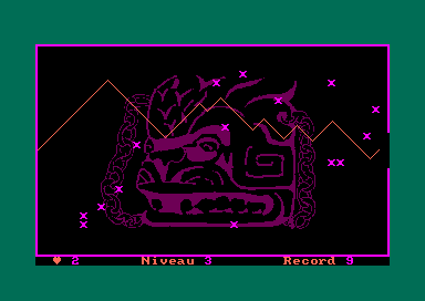
There are two possible orbits for this PRNG, each 8192 entries long:
- Starting seed 1 (899, 21769, 7835, …, 18745, 9003, 1, 899)
- Starting seed 5 (4495, 10541, 6407, …, 28189, 12247, 5, 4495).
The plot above is the first series as X and the second as Y. I used INTEGER*2 types to simulate the 1130’s narrow integers.


