More Micropython programmers — and especially beginners — should know about Awesome MicroPython. It’s a community-curated list of remarkably decent MicroPython libraries, frameworks, software and resources. If you need to interface to a sensor, look there first.
For example, take the INA219 High Side DC Current Sensor. It’s an I²C sensor able to measure up to 26 V, ±3.2 A. It does this by measuring the voltage across a 0.1 ohm precision shunt resistor with its built-in 12-bit ADC. I got a customer return from the store that was cosmetically damaged but still usable, so I thought I’d try it with the simplest module I could find in Awesome MicroPython and see how well it worked.
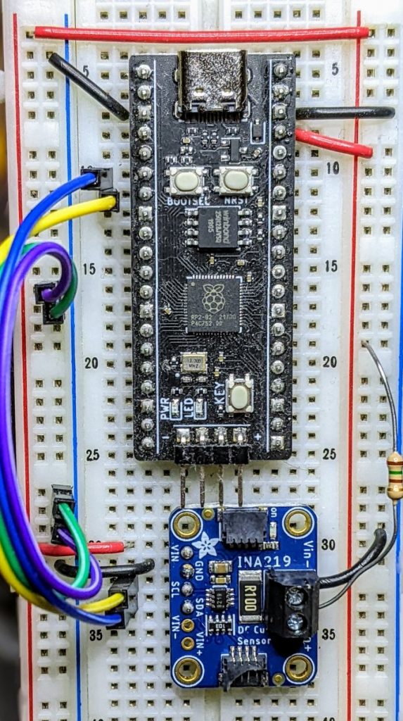
I guess I needed a test circuit too. Using all of what was immediately handy — a resistor I found on the bench and measured at 150.2 ohm — I came up with this barely useful circuit:
The INA219 would be happier with a much higher current to measure, but I didn’t have anything handy that could do that.
Looking in Awesome MicroPython’s Current section, I found robert-hh/INA219: INA219 Micropython driver. It doesn’t have much (okay, any) documentation, but it’s a very small module and the code is easy enough to follow. I put the ina219.py module file into the /lib folder of a WeAct Studio RP2040 board, and wrote the following code:
# INA219 demo - uses https://github.com/robert-hh/INA219

from machine import Pin, I2C
import ina219

i = I2C(0, scl=Pin(5), sda=Pin(4))
print("I2C Bus Scan: ", i.scan(), "\n")

sensor = ina219.INA219(i)
sensor.set_calibration_16V_400mA()

# my test circuit is 3V3 supply through 150.2 ohm resistor
r_1 = 150.2
r_s = 0.1  # shunt resistor on INA219 board

# current is returned in milliamps
print("Current       / mA: %8.3f" % (sensor.current))
# shunt_voltage is returned in volts
print("Shunt voltage / mV: %8.3f" % (sensor.shunt_voltage * 1000))
# estimate supply voltage from known resistance * sensed current
print("3V3 (sensed)  / mV: %8.3f" % ((r_1 + r_s) * sensor.current))
with everything wired up like this (Blue = SDA, Yellow = SCL):

Running it produced this:
I2C Bus Scan:  [64]

Current       / mA:   22.100
Shunt voltage / mV:    2.210
3V3 (sensed)  / mV: 3321.630
So it’s showing just over 22 mA: pretty close to what I calculated!
Hi. I have a question, it might be out off topic. Will the Mycropython libraries, frameworks interfacing with hall effect current sensor be much similar with INA219?
Hi Hopewell – no, it’ll be quite different.
The only Hall sensor I’ve used with MicroPython is the one built into many ESP32 processors. MicroPython’s esp32.hall_sensor() returns an integer related to the field strength. Other Hall sensors work more like a switch. I don’t know of any I2C Hall sensors, and the INA219 is an I2C device
Hi,
It works good for my ESP8266..! (need only small change : i = I2C( scl=Pin(5), sda=Pin(4)))…
I need to connect two INA219 to ESP8266 ..can you tell me how to specify the adresses in the program.
Thanks a lot
Abed
I think you’d need an I2C multiplexer, Abed, as the two devices will clash if on the same bus. Alternatively, if you have enough pins, you might be able to use SoftI2C for the other sensor
Hi Scruss,
Thanks a lot for your kind support …
I made it, and it works for the two INA219.
INA219 has two bits adress A0A1, so I leave the first INA219 to default adress 0x40 and for the second I soldered A0 and I left A1 open so I the adress will be 0x41 and my program became:
————————————————————–
from machine import Pin, I2C
import ina219
import time
i = I2C(scl=Pin(5), sda=Pin(4))
#print(“I2C Bus Scan: “, i.scan(), “\n”)
#time.sleep(5)
sensorA = ina219.INA219(i, addr=0x40)
sensorA.set_calibration_16V_400mA()
sensorB = ina219.INA219(i, addr=0x41)
sensorB.set_calibration_16V_400mA()
# my test circuit is 3V3 supply through 150.2 ohm resistor
#r_1 = 150.2
r_1 = 0
r_s = 0.1 # shunt resistor on INA219 board
while True:
print(“||Current A(mA): %8.3f” % (sensorA.current), ” ||Current B(mA): %8.3f” % (sensorB.current))
print(“||Shunt voltage A(mV): %8.3f” % (sensorA.shunt_voltage * 1000), ” ||Shunt voltage B(mV): %8.3f” % (sensorB.shunt_voltage * 1000))
print(“||3V3 (sensed) A(mV): %8.3f” % ((r_1 + r_s) * sensorA.current), ” ||3V3 (sensed) B(mV): %8.3f” % ((r_1 + r_s) * sensorB.current))
print(“||Power A(mW): %8.3f” % (sensorA.current * sensorA.shunt_voltage * 1000), ” ||Power B(mW): %8.3f” % (sensorB.current * sensorB.shunt_voltage * 1000))
print(“||========================================================================||”)
time.sleep(2)
———————————–