I’d tried making several Raspberry Pi Zero enclosures, but none of them quite worked. My needs are pretty simple, but I do need to be able to fit a full 40 pin strain-relieved (possibly keyed) header into the device while keeping questing fingers and dropped conductors off the circuit board.
So working from a (scaled) version of the Raspberry Pi Zero Mechanical Drawing, I made a case that meets some very basic requirements:
- Conserves material: The Coo~Coo uses just under 80 × 80 mm of 3 mm ply or acrylic, plus four nylon machine screws, nuts and washers.
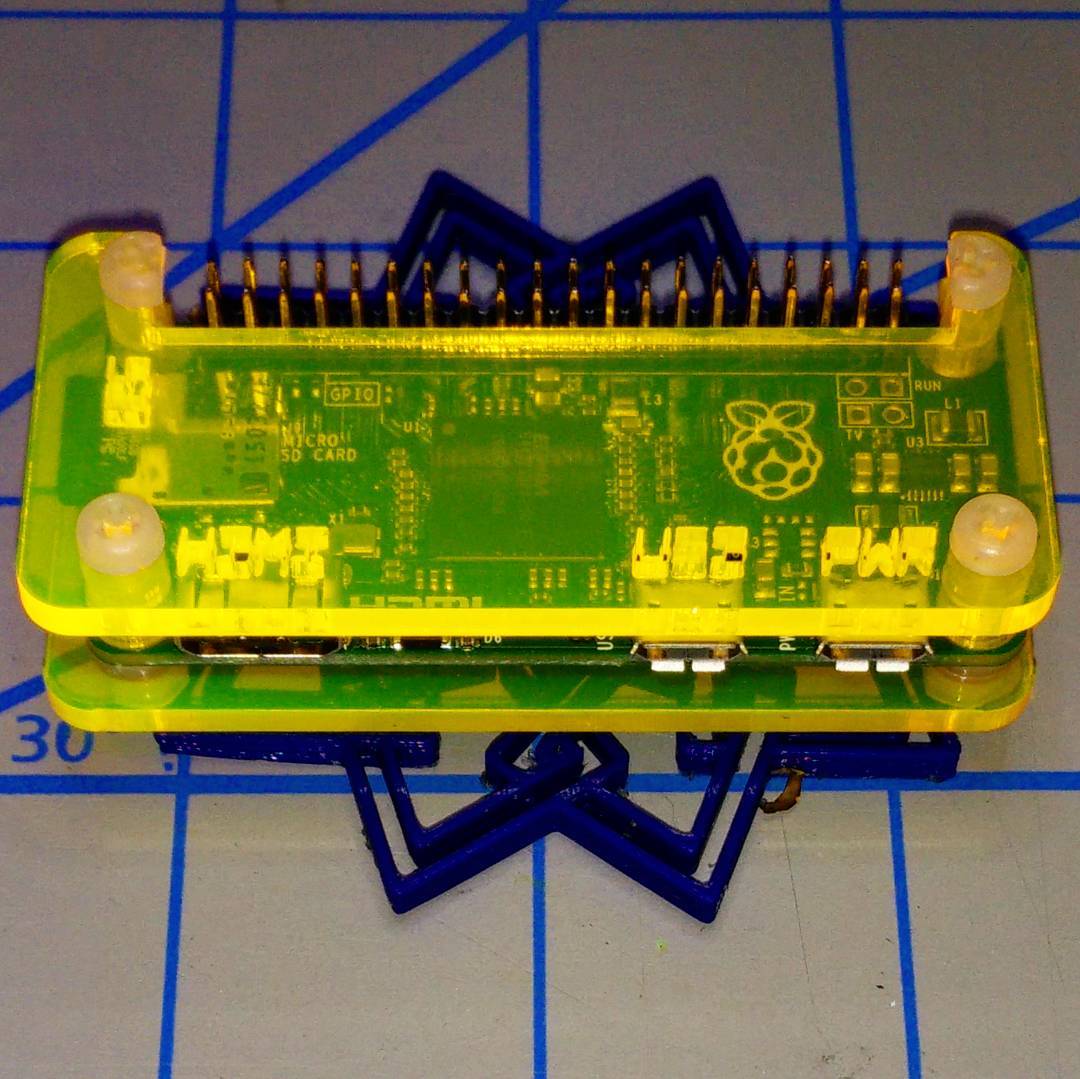
- Takes a full-sized GPIO header with a little headroom.
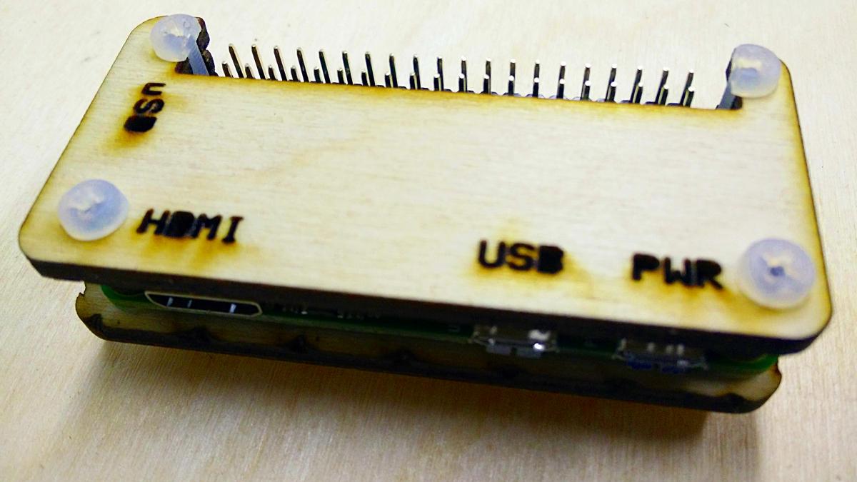
- Provides edge protection for the µSD and connectors.
- Has only a single cut layer, with no time-wasting engraved rasters.
- Needs only simple tools to make: really only needs diagonal cutters to snip off half of the nylon screw heads. Needle-nose pliers might help too, as there are some fiddly small parts.
- Free as in CC0. Yup, since this is derived from the Raspberry Pi Foundation’s copyrighted drawing, my modifications didn’t really add anything of value. Thus I waive all copyright and related or neighbouring rights on my additions:

To the extent possible under law, Stewart C. Russell has waived all copyright and related or neighbouring rights to the “Coo~Coo†Raspberry Pi Zero Case. This work is published from: Canada.
Why the odd “Coo~Coo†name? Well, look at the pattern of spacer washers and half-spacer washers:
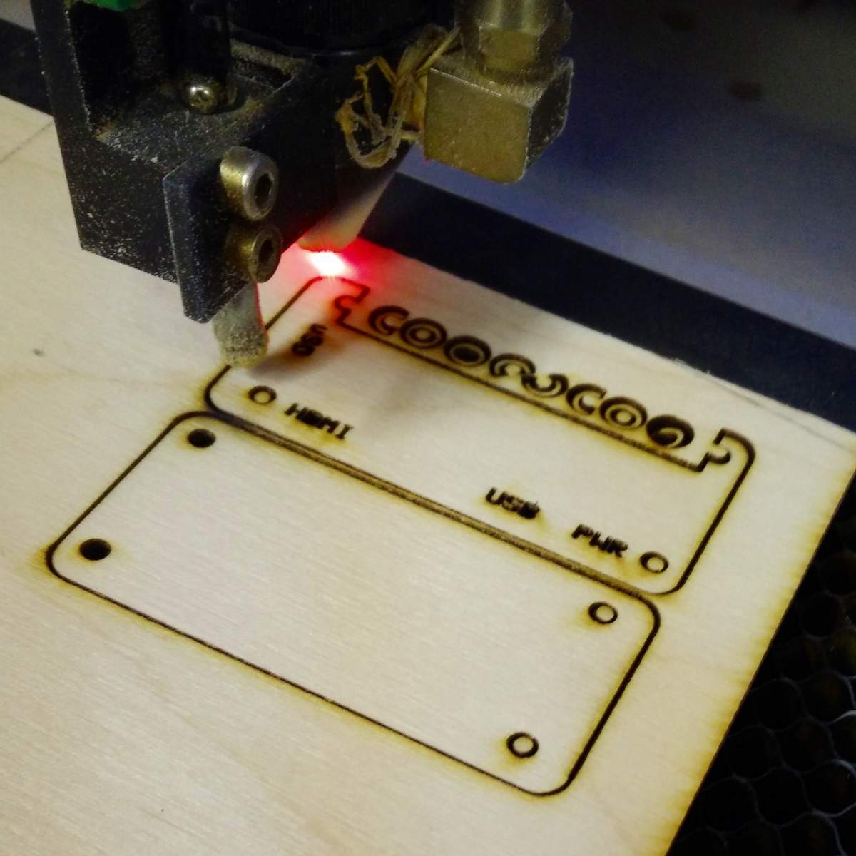
To save material, I arranged these washers inside the GPIO cutout. I realised that I could spell COO~COO. It’s even clearer on the cutting document:

Update: here’s a revised path that cut well with acrylic and probably will work slightly better on plywood, too: coo-coo-rpi_zero-acryl.zip
(If you do use acrylic, let me introduce you to one of the marvels of backing-paper removal: d-limonene. This fruity solvent — present in products like Goo Gone — causes backing paper to slough off with only a few minutes’ soaking. It washes off to a clean shine with water and dish soap/washing up liquid. I have just saved you fingernails from certain damage!)
The cutting path in the PDF could use a little clean up if you want to try this design in acrylic. The base of the design has been flipped so that any laser flare will be hidden inside the case.
You’ll need four M2.5 or M3 nylon screws of 20 mm length, plus 8 washers and 4 nuts. M3 screws of this length are easier to get, but the mounting holes in the Raspberry Pi Zero are only 2¾ mm in diameter. You can thin the M3 screws down slightly by lightly twisting them inside a piece of folded fine sandpaper. You’ll still have to push them through the Raspberry Pi Zero circuit board with a little force, though.
Cutting & Assembly Instructions
- If you have it, place some fine wire mesh or sacrificial heavy card-stock between the laser cutter honeycomb bed and the plywood. The spacer washers are just the right size to fall through the cutter bed and be lost inside the discard hopper.
- Cut the piece as normal.
- Remove the work from the laser cutter. Masking tape applied over the washers will stop them falling out.
- Take the top piece, and thread the other two screws through the holes by the HDMI and PWR labels.
(It may be easier to do these one at a time) - Place two of the full spacer washers over each screw.
- Push the screws through the Raspberry Pi Zero board. M2.5 screws won’t need any force, but M3 will need some coaxing, possibly even cajoling.
- Place a nylon washer on each of the two screws under the Raspberry Pi Zero board.
- Take the base and flip it horizontally so the screw holes match the top.
- Very loosely attach the nuts to each of the screws.
(You’ll need the slack to fit the top two screws and their C-shaped spacers) - Feed the top two screws through the half-holes by the GPIO cutout in the case and the Raspberry Pi Zero board. Again, coaxing and/or cajoling may be required if you used M3 ones.
- Put nylon washers over the screws between the Raspberry Pi Zero board and the base.
- Very loosely attach the nuts to the top two screws.
- (This is the fiddly bit) Stack two of the half spacers and put them on each screw. You need to get the screws tight enough to just grip the spacers against the case, but not too much or you won’t be able to align them to let the GPIO connector fit in the gap. Tightening the screws at the HDMI and PWR ports can help with this, too.
- Nip off half of the heads from two of the nylon screws. This will allow the GPIO connector to fit easily.
- Tighten all the screws (finger tight is fine) and make sure the trimmed heads align with the edge of the GPIO cutout.

The new Raspberry Pi Zero with camera connector should also fit, but I don’t have one to test it.
Leave a Reply