Spectrum is Green!

My previous adventures with my Sinclair ZX Spectrum 48K in Canada were not resounding successes. I couldn’t get the display to work, and tapes wouldn’t load well, so I’d been using Fuse while the hardware sulked in a cupboard.

I’d previously got a proper power supply (9 V DC, ≥ 1.4 A, centre negative) and bypassed the PAL UHF modulator to give composite video. No television, monitor or converter box that I had tried seemed to give a useful display.

Back in May, Walter Miraglia brought a tiny 7″ composite colour monitor to TPUG‘s Retrocomputing Night. He let me try it with the Spectrum, and it worked very well. Walter said it was an extension monitor for a car DVD player.

I dug around, and found that local surplus clearout store Tech Source Canada had the Philips 7″ portable DVD Player PD7016/37 for $60. This gives you two identical DVD players with composite input. I think my other one will be destined for a Raspberry Pi project somewhere.

To get these monitors running, you’ll need:

  • a 9–12 V DC power supply able to give ≥ 1 A. I use a regulated supply that gives 9.1 V open circuit and is rated at 2 A. Note that the power connector is slightly smaller than the common 2.1 mm barrel, so you may have to order this one, unless you can solder something up.
  • A cable like this 3.5mm Stereo to Composite Video + Audio Cable (3 RCA). These are sometimes just called camcorder cables. They use a 3½ mm TRRS jack, and can also — if you don’t mind not quite having the connectors in the right order — work with the composite/audio output of more recent Raspberry Pis. Tech Source had these for under $5.

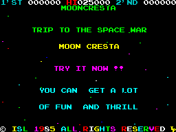
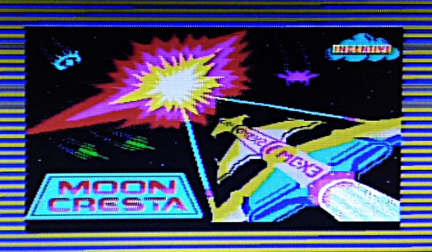
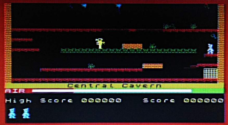
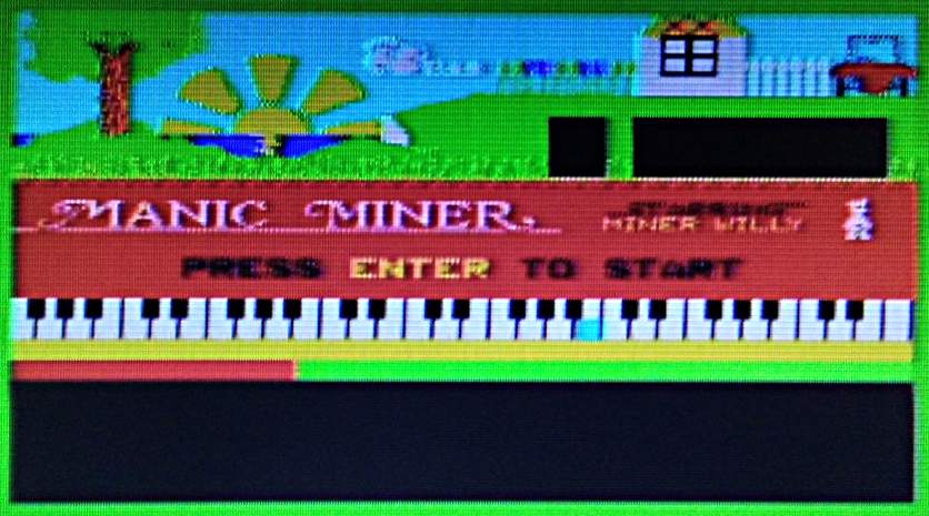
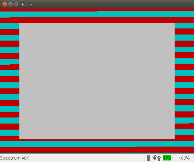
Connect it up , and — success! Well, slightly qualified success. The screens do not have the greatest resolution, so pixels are slightly smeared together. The screens do have a decently fast refresh, and the whole look is just right. With its colour clash and dot crawl, nobody ever expected great video from the Speccy anyway.

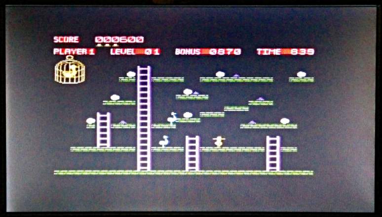
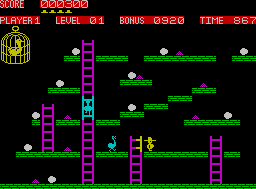
Here are some screen shots taken with my phone, and a couple of pixel-sharp screenshots from Fuse to compare:

Moon Cresta - complete with authentic weird language
Moon Cresta – complete with authentic weird language
Moon Cresta — the same screen from Fuse
Moon Cresta - nice loading screen
Moon Cresta – nice loading screen
Manic Miner — a game I am not good at
Manic Miner - perhaps the (deliberately?) worst game music ever
Manic Miner – perhaps the (deliberately?) worst game music ever
3D Death Chase — OH NOES A TREE!!!!1!!
Deathchase — OH NOES A TREE!!!!1!! Looks like the Riders of the Big Bikes just lost another member
Knight Lore
Knight Lore
Chuckie Egg
Chuckie Egg
Chuckie Egg from Fuse. We can't do anything about the attribute clash
Chuckie Egg from Fuse. We can’t do anything about the attribute clash

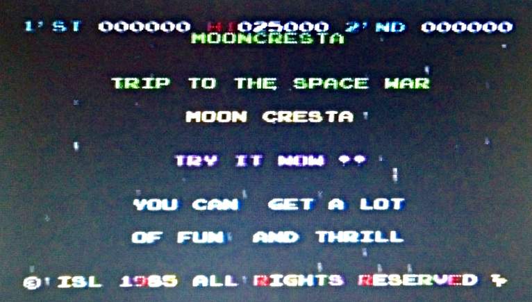
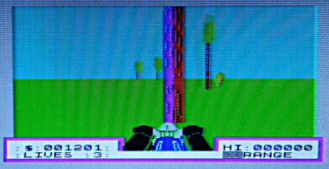
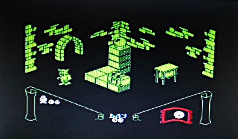
So I can now definitely view the screens. Huge thanks to Walter for tipping me off to these DVD players.

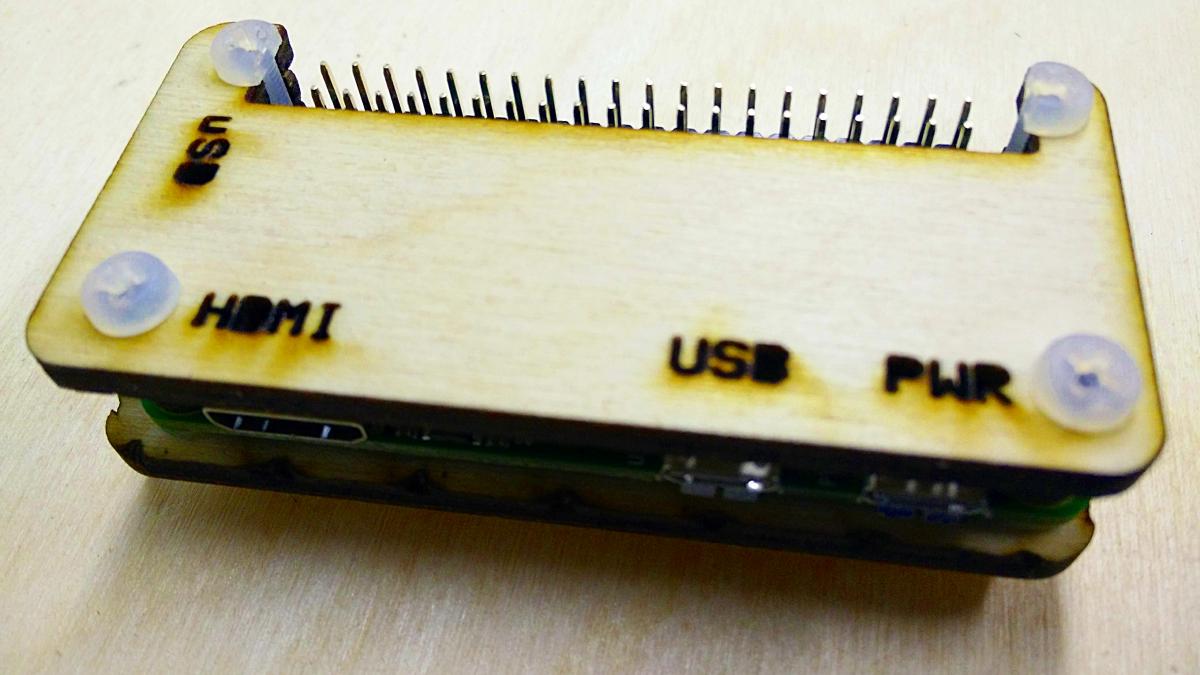
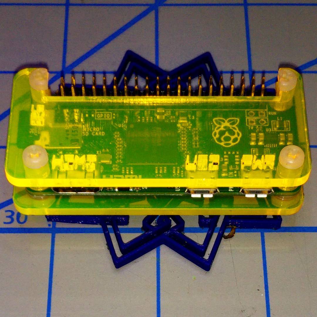
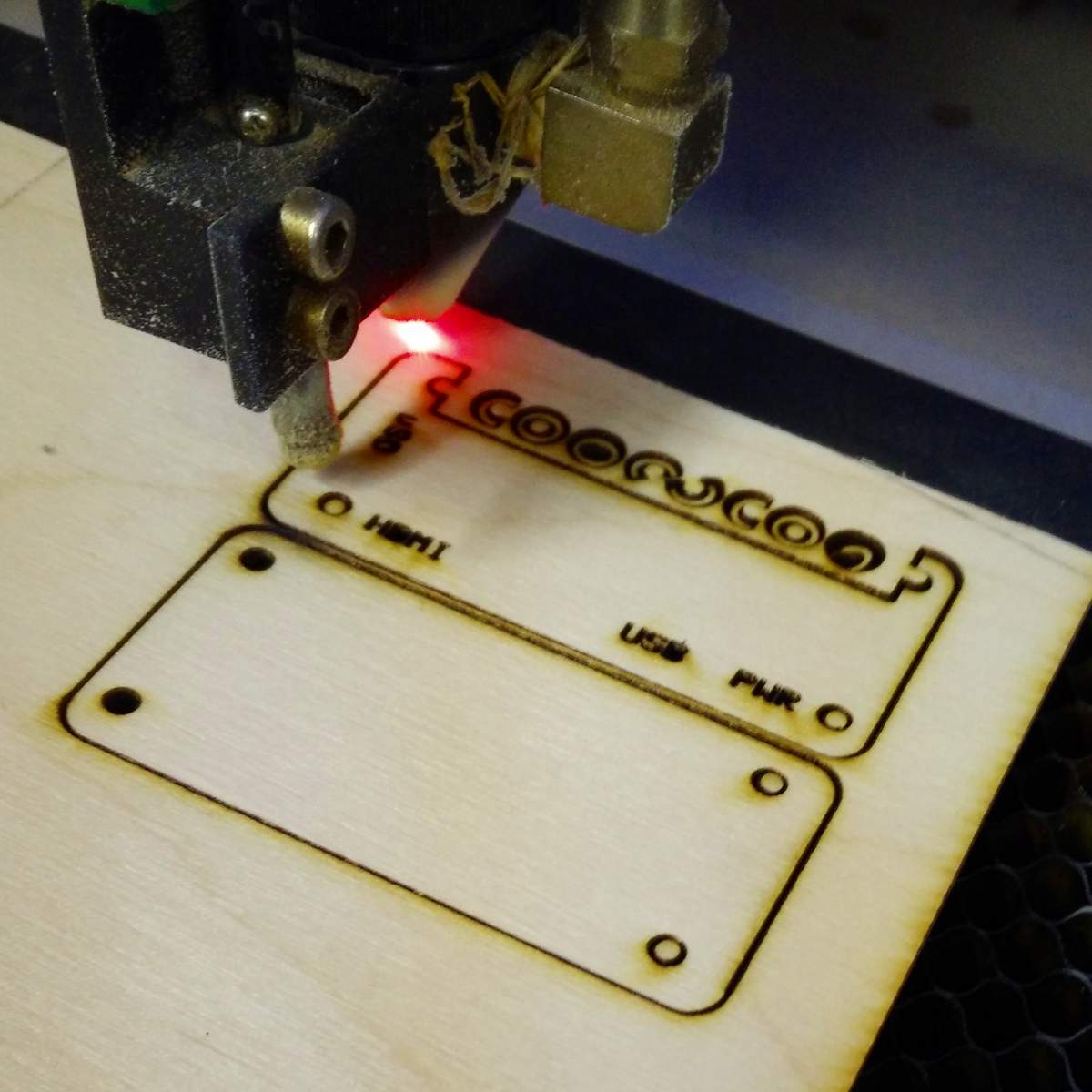
[Incidentally, the screens are designed for car use, so don’t stand up properly unless you get creative with some supports. I laser-cut these out of 3 mm plywood:

mini screen feet for 3 mm ply
mini screen feet for 3 mm ply. Cutting template PDF is linked underneath this image

Glue the little sticks on to the flat ends, and they’ll fit into the slots in the back of the monitor. Here are the feet with the sticks fitted:

screen feet with sticks glued in place

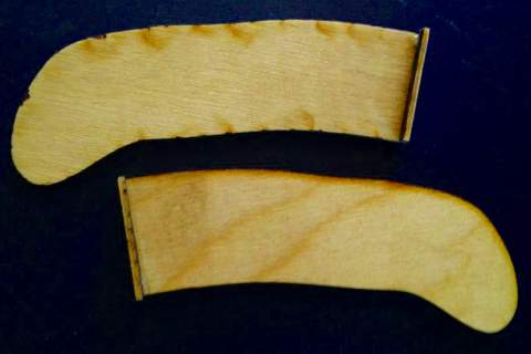
There are better-designed feet than these, but they work, mostly.]

I was still having game loading problems. Try as I might, I couldn’t get anything to load reliably. Retrocomputing Stack Exchange came to the rescue, in the shape of mcleod_ideafix’s very helpful answer.  If your audio player is running from batteries and you can use a stereo cable, you can convert the normal mono loading audio into stereo with one channel inverted. This gives you effectively double the volume, and works quite well with my audio player, an old Edirol R-1*.

Inverted stereo loading data, showing 4000/8000 Hz speedload tones
Inverted stereo (or differential) loading data, showing 4000/8000 Hz speed-load tones

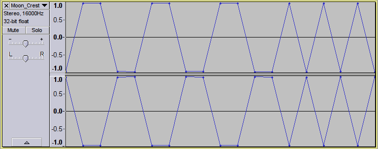
This audio will not load into an emulator, or work with a mono cable. Some audio players even render it as silence.

Here’s a script to take monophonic loading data and convert it to this faux-differential stereo format using Sox:

#!/bin/bash
# wav2differential.sh - convert mono game tape audio to 2× stereo
# usage:   wav2differential.sh infile.wav
#          (creates  infile-differential.wav)
# scruss - 2016-06-07
# method by ‘mcleod_ideafix’; many thanks / greetz
#   — https://retrocomputing.stackexchange.com/a/774/439

base="${1%.wav}"
sox -q --norm=-3 "$1" -b 16 "${base}-n.wav"
sox -q  "${base}-n.wav" "${base}-ni.wav" vol -1.0
sox -q  --norm=-0.1 -M -c 1 "${base}-n.wav" -c 1 "${base}-ni.wav" -c 2 -b 8 "${base}-differential.wav"
rm -f  "${base}-n.wav" "${base}-ni.wav"

If you want to check your audio levels, sox can also create the 800 Hz header tone used by the Spectrum. Run the output of the command below through the script above, load it onto your audio player and fiddle with the volume until the border flickers steadily:

sox -n -b 8 -r 8000 800hz-header.wav synth 30 square 800
Lovely loading bars ...
Lovely loading bars …

I was also looking for the games to load fairly quickly. Tapes used to take over three minutes to load, and while retrogaming all is about the experience, I haven’t got time for that. Fuse has some utility programs which will convert a .Z80 game snapshot into an audio file that loads in about 1¼ minutes.

To convert the snapshot to a speed-load TZX tape image:

snap2tzx -o game.tzx -s 3 game.z80

To convert that virtual tape image into audio:

tape2wav -r 16000 game.tzx game.wav

You can then run that WAV file through the stereo/differential script I listed above. Have fun!

The “Coo~Coo” Raspberry Pi Zero Case

Coo~Coo Raspberry Pi Zero Case - built
Coo~Coo Raspberry Pi Zero Case

I’d tried making several Raspberry Pi Zero enclosures, but none of them quite worked. My needs are pretty simple, but I do need to be able to fit a full 40 pin strain-relieved (possibly keyed) header into the device while keeping questing fingers and dropped conductors off the circuit board.

Coo~Coo case in fluo acrylic

So working from a (scaled) version of the Raspberry Pi Zero Mechanical Drawing, I made a case that meets some very basic requirements:

  1. Conserves material: The Coo~Coo uses just under 80 × 80 mm of 3 mm ply or acrylic, plus four nylon machine screws, nuts and washers.
  2. Takes a full-sized GPIO header with a little headroom.
  3. Provides edge protection for the µSD and connectors.
  4. Has only a single cut layer, with no time-wasting engraved rasters.
  5. Needs only simple tools to make: really only needs diagonal cutters to snip off half of the nylon screw heads. Needle-nose pliers might help too, as there are some fiddly small parts.
  6. Free as in CC0. Yup, since this is derived from the Raspberry Pi Foundation’s copyrighted drawing, my modifications didn’t really add anything of value. Thus I waive all copyright and related or neighbouring rights on my additions:


    CC0

    To the extent possible under law, Stewart C. Russell has waived all copyright and related or neighbouring rights to the “Coo~Coo” Raspberry Pi Zero Case. This work is published from: Canada.

Why the odd “Coo~Coo” name? Well, look at the pattern of spacer washers and half-spacer washers:

Coo~Coo in the cutter

To save material, I arranged these washers inside the GPIO cutout. I realised that I could spell COO~COO. It’s even clearer on the cutting document:

Coo~Coo — PDF for cutting is linked under the image

Update: here’s a revised path that cut well with acrylic and probably will work slightly better on plywood, too: coo-coo-rpi_zero-acryl.zip
(If you do use acrylic, let me introduce you to one of the marvels of backing-paper removal: d-limonene. This fruity solvent — present in products like Goo Gone — causes backing paper to slough off with only a few minutes’ soaking. It washes off to a clean shine with water and dish soap/washing up liquid. I have just saved you fingernails from certain damage!)

The cutting path in the PDF could use a little clean up if you want to try this design in acrylic. The base of the design has been flipped so that any laser flare will be hidden inside the case.

You’ll need four M2.5 or M3 nylon screws of 20 mm length, plus 8 washers and 4 nuts. M3 screws of this length are easier to get, but the mounting holes in the Raspberry Pi Zero are only 2¾ mm in diameter. You can thin the M3 screws down slightly by lightly twisting them inside a piece of folded fine sandpaper. You’ll still have to push them through the Raspberry Pi Zero circuit board with a little force, though.

Cutting & Assembly Instructions

  1. If you have it, place some fine wire mesh or sacrificial heavy card-stock between the laser cutter honeycomb bed and the plywood. The spacer washers are just the right size to fall through the cutter bed and be lost inside the discard hopper.
  2. Cut the piece as normal.
  3. Remove the work from the laser cutter. Masking tape applied over the washers will stop them falling out.
  4. Take the top piece, and thread the other two screws through the holes by the HDMI and PWR labels.
    (It may be easier to do these one at a time)
  5. Place two of the full spacer washers over each screw.
  6. Push the screws through the Raspberry Pi Zero board. M2.5 screws won’t need any force, but M3 will need some coaxing, possibly even cajoling.
  7. Place a nylon washer on each of the two screws under the Raspberry Pi Zero board.
  8. Take the base and flip it horizontally so the screw holes match the top.
  9. Very loosely attach the nuts to each of the screws.
    (You’ll need the slack to fit the top two screws and their C-shaped spacers)
  10. Feed the top two screws through the half-holes by the GPIO cutout in the case and the Raspberry Pi Zero board. Again, coaxing and/or cajoling may be required if you used M3 ones.
  11. Put nylon washers over the screws between the Raspberry Pi Zero board and the base.
  12. Very loosely attach the nuts to the top two screws.
  13. (This is the fiddly bit) Stack two of the half spacers and put them on each screw. You need to get the screws tight enough to just grip the spacers against the case, but not too much or you won’t be able to align them to let the GPIO connector fit in the gap. Tightening the screws at the HDMI and PWR ports can help with this, too.
  14. Nip off half of the heads from two of the nylon screws. This will allow the GPIO connector to fit easily.
  15. Tighten all the screws (finger tight is fine) and make sure the trimmed heads align with the edge of the GPIO cutout.
Raspberry Pi Zero in Coo~Coo case showing GPIO and spacers

The new Raspberry Pi Zero with camera connector should also fit, but I don’t have one to test it.