Instagram filter used: Normal
Update: hey, you probably don’t want to do this too much. For complicated reasons, Inkscape (and Illustrator, and most other drawing packages) approximate circles with Bézier segments. These look like circles, but aren’t. If you need accuracy, use Inkscape’s Polygon tool and only use the vertices it creates. A lot of the patterns I was making round about the time I wrote this don’t quite tessellate properly.
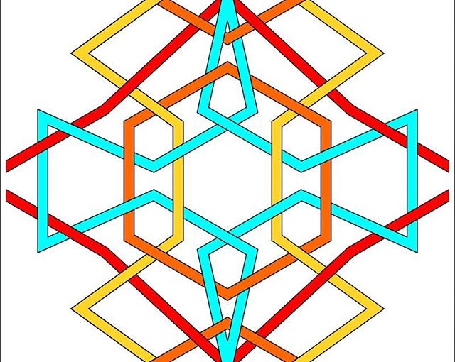
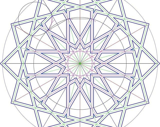
Drawing a circle between a centre point and one on the circumference is a common requirement in working up geometric patterns. If you need lines parallel to a radial line, or indeed any line at a fixed distance from another point, you need to draw a circle as a construction guide. the figure below will never be destined for design greatness, but it shows how they could be used:

The turquoise circles define the green parallel lines, and also the smaller green hexagon inside the black one. Drawing circles from a centre is what compasses do, yet Inkscape doesn’t have a tool to do it easily.
There is a way around this, though, that I picked up from this forum post. The poster’s method isn’t very clear, but in very brief summary, you need to construct a 3 point or 2 line-segment polyline with its nodes equidistant from the centre point, then use Render → Draw from Triangle … → Circumcircle to construct the circle. Simple? Um …
Okay, dodgy animation and point by point explanation coming up. With cusp, intersection and centre snapping all enabled:
There’s probably another way to do this by creating a point (Ctrl+click in Line mode) giving it a line width, setting rounded line ends, then doing Path→Stroke to Path to get a buffer around the point, but I can’t work out how to do this reliably.
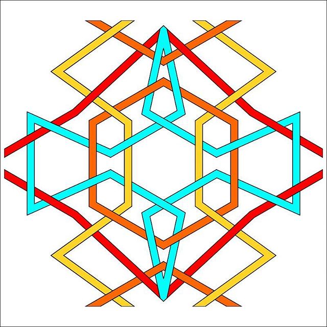
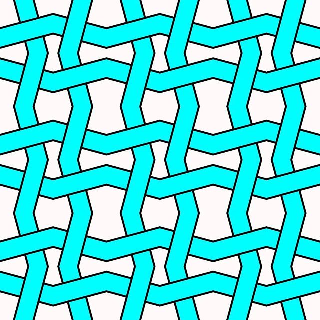
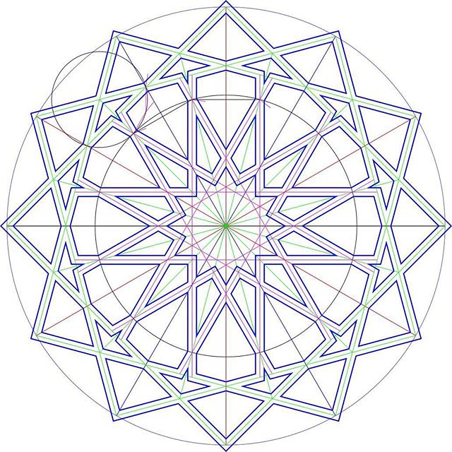
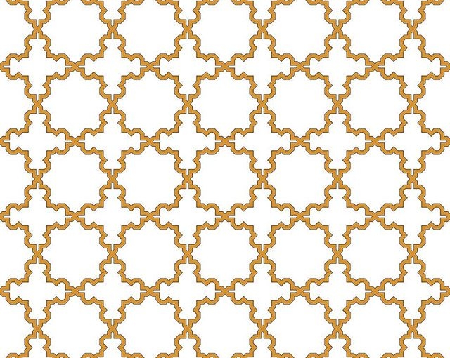
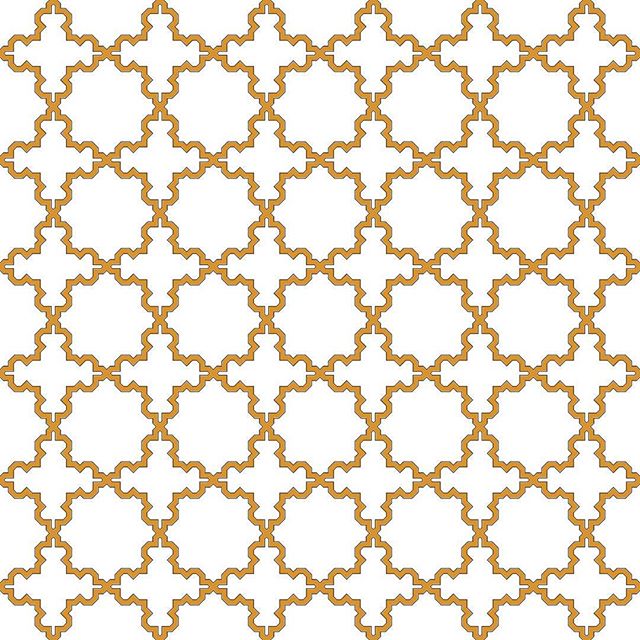
Oh, and the patten I made from the construction? Well, it might look okay on a paper towel …
Richard gave me this book of logarithms, Dr Bruhns’ A new manual of logarithms to seven places of decimals. It had been lurking in his family library for decades. Just look at the layout!
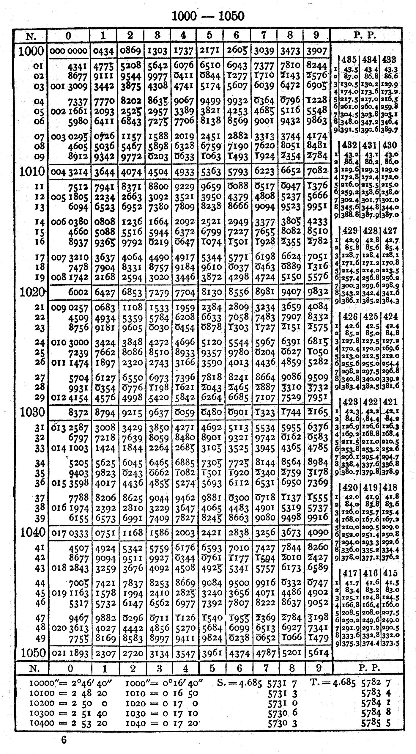 This is packing a ridiculous amount of information on the page. It’s dropping as many leading digits as it can: instead of showing log10 1001 as 3.0003431, it assumes you know the power of ten, leaves out leading zeroes, and shows it as ‘3431’. Another trick it uses to save space is printing logs of numbers less than one (which would be negative) as 10 + that logarithm. So log10 (1/ðœ‹) ≅ log10 (0.3183099) ≅ -0.4971499 would be represented by 9.5028501. You get the right significand, just the result is off by 10 orders of magnitude (since 10ð‘¥+10 = 10ð‘¥Ã—1010). I guess keeping track of the powers of ten was just considered mundane housekeeping.
Richard wondered why the book had Printed in Germany overstamped with Printed in USA:
 Given the date, it’s likely that it was printed from plates, rather than a photographic offset litho process. These plates were expensive to modify, so for a student reprint of a well-established textbook, it would have been cheaper to hand-stamp over the front page.
Because accuracy of reproduction is important for log tables, the many editions of Dr Bruhns’ tables were proud to be copied from printing plates so no new errors were introduced:
![]() Stereotyping was an old way of copying printing plates, first with papier maché, and later by electroplating/electrotyping. Because it was a cheap way of getting articles and pictures reproduced in newspapers, stereotype came to have its modern meaning. The word cliché also comes from the same process, as it was an onomatopoetic French word for the sound of molten casting metal hitting the papier maché mould.
Stereotyping was an old way of copying printing plates, first with papier maché, and later by electroplating/electrotyping. Because it was a cheap way of getting articles and pictures reproduced in newspapers, stereotype came to have its modern meaning. The word cliché also comes from the same process, as it was an onomatopoetic French word for the sound of molten casting metal hitting the papier maché mould.
There are many copies of this book in the Internet archive:
Anyone want to check ’em for errors? There used to be a Prussian gold piece available if you found an error, but Prussia’s not returning our calls these days.
There’s one last surprise (or potential horror) in the book: a table of local definitions of the foot measure before metrication (and, since Dr Bruhns gotta bruhn, the logs of each number):
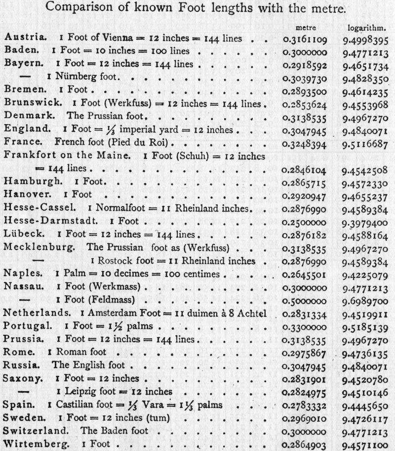 None of these are equal to the US customary foot, which is 0.3048 m precisely. The British and Russian foot are close, at 0.3047945 m. The US Survey foot isn’t represented either. Go on yourself, Mecklenburg and the Netherlands, with your plucky 11 inches to the foot (wat?). And I couldn’t leave you without a helpful instance of an obsolete measure symbol, the line, 1‴ (that’s U+2034) being 1/12″ or 2.116667 mm. Why code point space is being wasted on that and there isn’t a symbol for the wonderful HP plotter unit (1/40 mm, or 0.000025 m, which also happens to be the round[ish] 1/1016″) I will never know …
You might have noticed that I’ve become a bit obsessed with Arabic/Islamic geometric designs lately. Clues include posts like this, this, also this, and maybe even this. When I refer to Islamic Geometric Design, I’m more talking about the frameworks, repeat units or grids that are the starting point for the intricate and hypnotic abstract designs that have traditionally been used in Islamic architecture for over a thousand years. Here’s an example of the larger patterns in context:

“A close up of [The Tomb of Bibi Jawindi, Uch, Pakistan] by Usman Ghani” by Usman.pg – Licensed under CC BY-SA 3.0 via Wikimedia Commons.
I’ve been following Eric Broug‘s methods of construction that use a ruler and compass exclusively. Not being that great with manual dexterity, I’ve found these much slower to draw than I could on a computer. Consequently, I looked around for a good, free tool that people could use to start making these drawings. Most of the operations (including drawing from one intersection to another, rotating objects around a point, buffering lines into polygons) can be done by CAD packages, but these often have a steep learning curve. CAD packages also don’t tend to have many artistic functions.
Thankfully, the free drawing packing Inkscape has almost all of the features I need. Just one of the features I use quite often (creating a circle from a centre point and a point on the circumference; in other words, emulating a compass) isn’t built in, but can be done with a simple sequence of operations. In this article, I hope to show you some techniques you can build on for making your own patterns.
This is covered well on the Inkscape website, so I won’t repeat it here. It’s important to get the most recent stable version of Inkscape. Some Linux distributions provide a really old version, so make sure you’re using at least version 0.91.
Inkscape runs on Linux, Mac and Windows. On Mac, it’s a little slow and uses some non-(Mac-)standard keyboard shortcuts. You may also have to install XQuartz on your Mac for it to run. It works fine on Windows (I tested 8.1).
![]()
You’re going to have to get to know and love the Snapping Toolbar, shown at right. When you enable snapping, the items you draw or modify are locked to the node, intersection, object centre or grid point nearest to your cursor. When snapping is active, you get a little hovering info box showing you what Inkscape thinks you want to snap to:
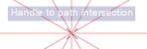
I’ve enlarged the screen grab so you can make the info box out more clearly.
Snapping allows you to place lines in geometrically precise locations if you work up a drawing from a template or construction lines. All of the templates I made have the most useful snapping modes enabled:

(source SVG is linked from image)
Here’s a simple example of a triangle drawn from construction lines. I couldn’t ever draw a perfect equilateral triangle freehand, but with snapping, it’s four clicks (three vertices, then a final click on the first vertex to close the figure), and it’s done perfectly.
Incidentally, most of the patterns I make use straight lines. In Inkscape, you’ll want to use the Pen tool (![]() ) with straight lines enabled (
) with straight lines enabled (![]() ).
).
When you double-click an object in Inkscape in Select & Transform mode (![]() ), you get shown the rotation handles and the all-important Centre of Rotation. By default, the centre of rotation is in the centre of the bounding box of the object; that is, the centre of the smallest horizontal box that encloses the object. Here it’s marked by a small cross:
), you get shown the rotation handles and the all-important Centre of Rotation. By default, the centre of rotation is in the centre of the bounding box of the object; that is, the centre of the smallest horizontal box that encloses the object. Here it’s marked by a small cross:
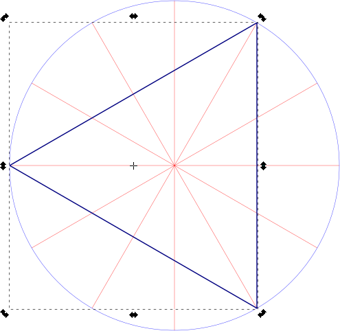
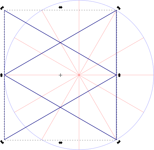
Let’s say we want to make a six-pointed star from this triangle. You might think that if you duplicated it (keyboard shortcut: Ctrl+D) and flipped it horizontally (keyboard shortcut: h), you’d get your star. Alas, no star for you:
What we wanted to do was to flip the triangle around the centre of rotation of the radial construction lines, and to do that we need to drag the triangle’s centre of rotation over to the centre of the construction lines:
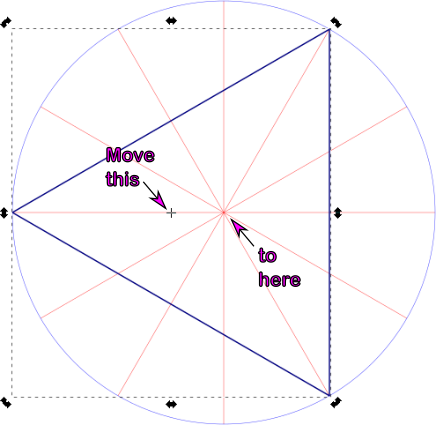
You’ll know when you’ve got it in the right place, as Inkscape’s snapping info box should tell you:

Let’s try that duplication and flipping thing again:
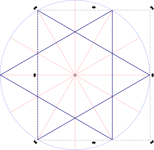
Moving the centre of rotation makes all the difference.
Now that we can move the centre of rotation, we can use that to build up compound objects:

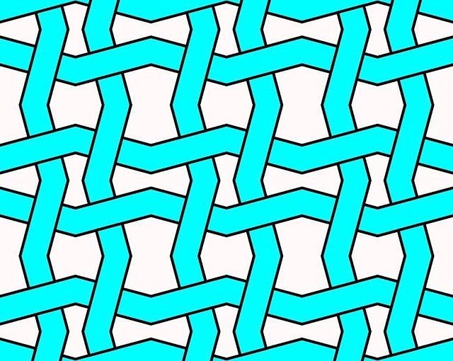
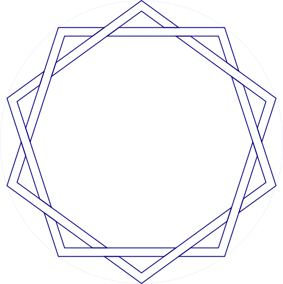
This interleaved set of strapwork pentagons is made from 10 segments:

(source SVG is linked from image)
Since there are 10 segments, we have to rotate each segment 36° (= 360°/10) to fill up the whole circle. For this, we use the Transform tool’s Rotate tab:
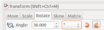
If you’re wanting to avoid doing even division in your artwork, here’s a table for many common values:
| Number of Segments | Rotation / ° |
| 2 | 180 |
| 3 | 120 |
| 4 | 90 |
| 5 | 72 |
| 6 | 60 |
| 8 | 45 |
| 10 | 36 |
| 12 | 30 |
| 16 | 22.5 |
| 18 | 20 |
| 20 | 18 |
| 24 | 15 |
| 36 | 10 |
Applying nine duplicate-rotate steps, we get this result:
(work in progress …)

(SVG source linked from image)
Most geometric figures have lines with some thickness to them. Guide lines alone are pretty boring.
You can use Object → Fill & Stroke and set Stroke Style on a path to make it wider, but sometimes you might want to work with the intersections of the edges of these paths. Fortunately, Inkscape makes this relatively easy.
First, give your path the width you want, say 3-5 mm. Then, with the path selected, use Path → Stroke to Path. At first, nothing appears to have happen, but change the Fill to none (the ‘×’ icon) and the Stroke Paint to solid. Suddenly, the path will appear to get really thick, but reduce the Stroke Style: Width down to a fine line, and you’ll end up with the outline of your original path.

(SVG source linked from image)
I’ve jumped ahead a bit with the illustration, and started to fill in the strapwork. Inkscape will snap to the nodes on the edges of your figure, and you can decorate it any way you wish.
(The Stroke Style: Join and Stroke Style: Cap permanently affect the outline path. You’ll get quite good at using Undo until you get the effects you want. Really pointy shapes will need a custom Stroke Style: Mitre Limit, as graphics programs try to limit really acute intersections, as they can get awkwardly long and trail off the page.)

(SVG source linked from image)
I’m still happily using a Raspberry Pi 2B 3 as a lightweight desktop machine. It’s not my main computer, but it’s pleasantly capable. Set up with a couple of paged desktops (or virtual desktops, as we used to call ’em), I can get a bunch of things done with it.
One feature that really irked me, though, was the way that window switching worked. Or, for greater clarity, didn’t work. Openbox, the standard window manager in Raspbian, didn’t allow you to switch to windows on another desktop with Alt+Tab. As I have a smallish screen, I typically have very few windows per desktop, so I want that ability to move from task to task.
This, however, can be fixed. In your ~/.config/openbox/lxde-pi-rc.xml file, change the keybinding sections for Alt+Tab and Alt-Shift+Tab from:
    <!-- Keybindings for window switching -->
    <keybind key="A-Tab">
      <action name="NextWindow"/>
    </keybind>
    <keybind key="A-S-Tab">
      <action name="PreviousWindow"/>
    </keybind>
to
    <!-- Keybindings for window switching -->
    <keybind key="A-Tab">
      <action name="NextWindow">
        <allDesktops>yes</allDesktops>
      </action>
    </keybind>
    <keybind key="A-S-Tab">
      <action name="PreviousWindow">
        <allDesktops>yes</allDesktops>
      </action>
    </keybind>
Log out, log back in, and Alt+Tab across desktops should Just Work. If you’re not using the default pi user, I suspect you’ll have to edit the ~/.config/openbox/lxde-user-rc.xml file instead.
Credit for this tip: user crunchworksyeay on the CrunchBang Linux Forums.
This has been a Memo To Myselfâ„¢ production.
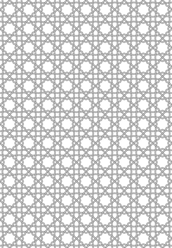
I’m rather pleased with this, as it’s the first pattern I’ve worked out from a real example, a screen in the Aga Khan Museum:
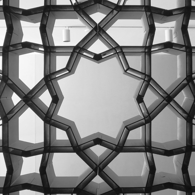
Here’s the pattern as a full page PDF from Inkscape: akm-screen-tiled-strapwork.pdf. The pattern’s not much more than an 8-pointed star with a smaller 8-pointed star inside it, rotated 22½°. But it’s still kinda neat.
I bought a CD-ROM, The World of Patterns. It’s supposed to work on ‘Any computer with an Internet browser and a CD-ROM drive’. Guess I don’t just have any computer, then …
The disk — an interesting mathematical/artistic study of patterns — is arranged as a tree of HTML files, with internal links and images. This is how the folders appear on my computer:
├── art
│   ├── islam
│   ├── preislam
│   └── pstislam
│   ├── latt
│   ├── other
│   └── quilts
│   ├── modern
│   │   ├── large
│   │   ├── patch3
│   │   └── patch4
│   └── usa
├── info
├── maths
All neatly lower case, as one might expect. Unfortunately, the internal links are hard-coded to access links such as /art/Islam/over.htm, and Linux, being good and literal, can’t find the upper case ones.
Unfortunately, the majority of computers quietly ignore the case of letters on removable media. Linux’s insistence on being correct is at odds with what is generally considered useful. But there’s a way around this. You can give the mount command options to tell it to be more chill about case:
sudo mount -t iso9660 -o loop,check=relaxed,map=normal,norock,nojoliet disk.iso /mnt/scratch/
This works for me quite well:
The CD-ROM is interesting, if a little dated. The author has gone on to produce the website tilingsearch.org, a huge database of historical tile patterns.
These SVG templates are modelled after Eric Broug‘s drawing templates for Islamic Geometric Design pattern elements. Although written for Inkscape, they should be usable with almost any graphics program.
By enabling snapping to nodes and object centres, your drawing program can act like an accurate straight edge and compass for constructing geometric figures.
The files are name N-LL-S.svg, where:
Examples:
4-12-6.svg — base symmetry 4-fold (square/diamond), with 12 lines or 30° spacing. Hexagonal (6-fold) guidelines are highlighted in a different colour.5-10-0.svg — base symmetry 5-fold (pentagonal), with 10 lines or 36° spacing. No other guidelines are highlighted.In Inkscape 0.91:
WTFPL (srsly).
All files, zipped: radial-templates-for-inkscape.zip
Individual files, with SVG linked behind image:


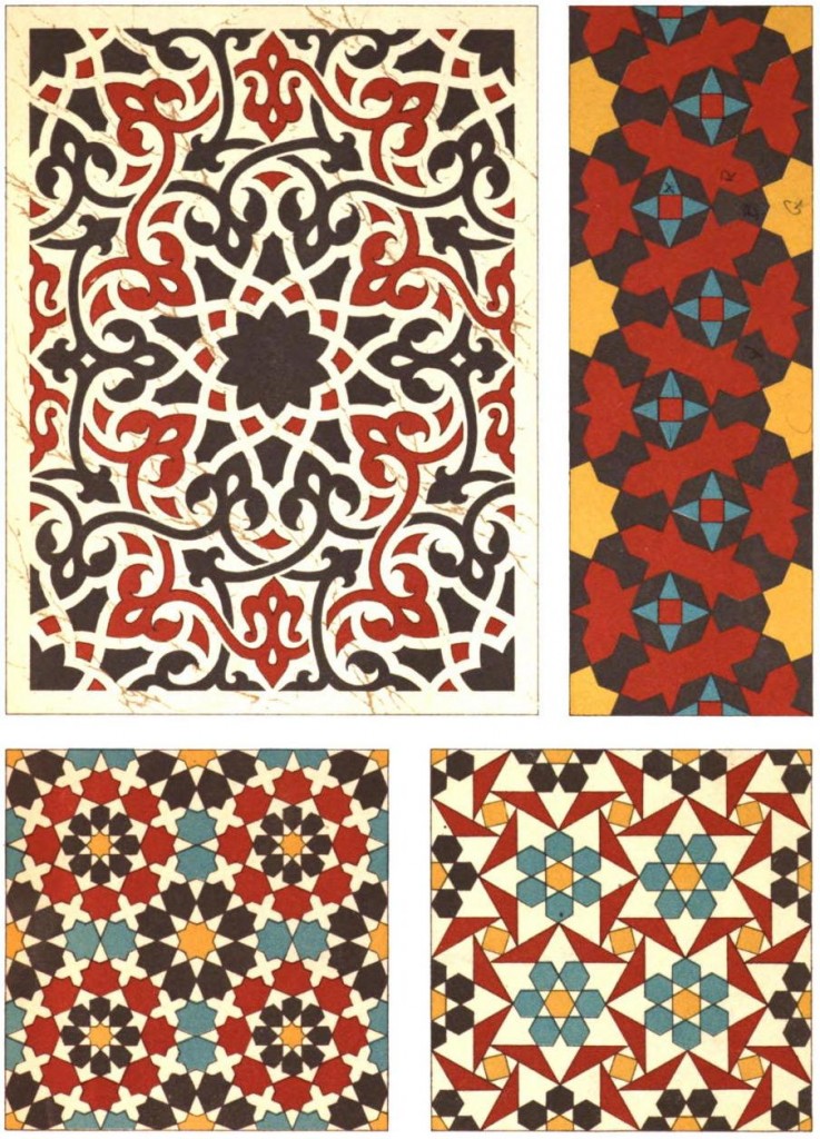 Just uploaded Les éléments de l’art arabe: Le trait des entrelacs by Jules Bourgoin (aka Arabic Geometrical Pattern & Design) to archive.org. This is much cleaned up from the Google Books scan, which had many duplicate pages and no metadata.
This is much better than the (now returned) Kindle edition …
Product link: Arabic Geometrical Pattern and Design (Dover Pictorial Archive) eBook: J. Bourgoin: Amazon.ca: Kindle Store
Summary: Buy the paper edition; this book is illegible on Kindle.
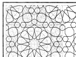
The original book features very finely engraved line drawings, with construction lines showing how the patterns are built up. The Kindle edition has only low-resolution scans, so the lines break down into noise and are very hard to follow. You can’t zoom in, either. The figure numbering is entirely absent from the Kindle edition, so you can’t use this book for reference. Some of the page scans are squint and partially cut off, too.
Very disappointed in this purchase. You’re better off with the paper than trying to squint at these smudgy pixels.
(unedited text as simultaneously posted to Amazon)
![]()