SeeedStudio Wio Terminal

Small screen device showing geometric pattern
Wio Terminal displaying … some kind of nonsense of mine

Some months ago, when Chloe from Seeed Studio got in touch and asked me if I’d like to write about their new Wio Terminal device, I didn’t waste any time in saying yes. I mean, would you say no to all of this?

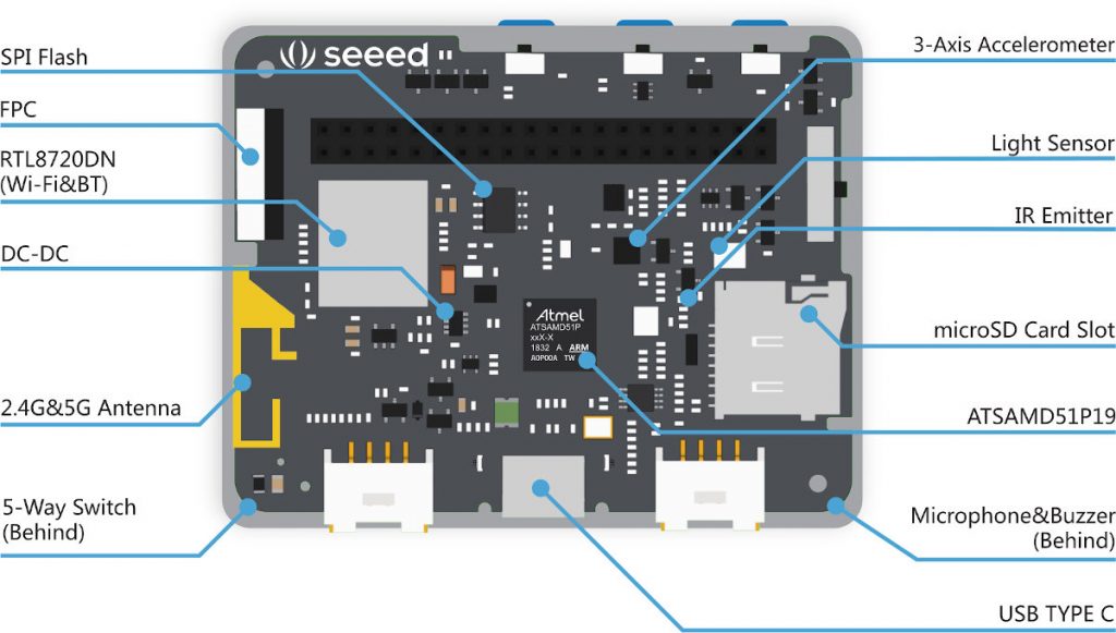
  • 120 / 200 MHz ARM Cortex-M4F core (MicroChip ATSAMD51P19: 512 KB Flash, 192 KB RAM) with additional 4 MB Flash program/data storage and micro-SD card slot;
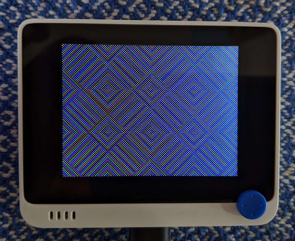
  • 2.4″ 320 × 240 colour screen;
  • Realtek RTL8720DN wifi / Bluetooth transceiver;
  • buttons, joystick, accelerometer, RGB LED, light sensor and IR transmitter;
  • neat case (72 × 57 × 10.4 mm) with magnetic and screw mounts;
  • Grove connectors for wiring free sensor mounting.
Wio Terminal internals
Wio Terminal internals (from Wio Terminal User Manual)

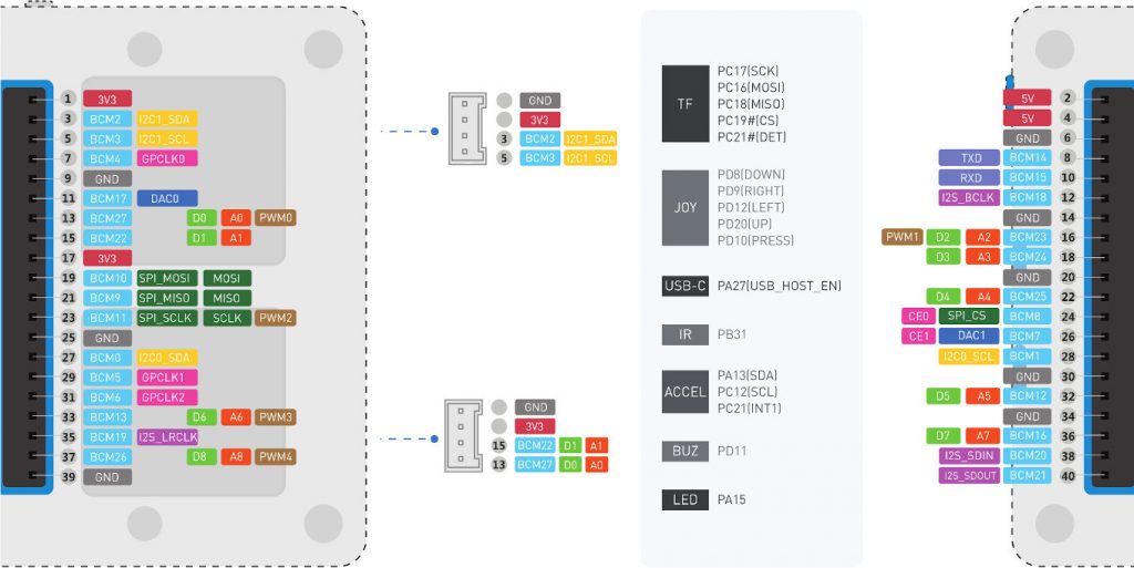
It’s got a Raspberry Pi-type header that claims compatibility. The documentation for all the ports is a cut above the usual no-name ESP8266 / STM32 stuff:

Wio Terminal pinout
Wio Terminal pinout (from Wio Terminal User Manual)

The device is in a really tidy package. Its screen, although not a touchscreen, is super sharp.

individual pixels magnified from the Wio Terminal screen
The screen is very nice: individual pixels zoomed in

There are three ways of programming the Wio Terminal:

  1. Arduino
  2. SeeedStudio’s own ArduPy
  3. CircuitPython

Each of these have pros and cons.

Arduino (get started)

  • the fastest code execution: compiled ARM binary code
  • the only way to access wifi and Bluetooth (currently)
  • slow development cycle
    (… is it just me, or has the Arduino IDE got really 🦥🦥🦥 recently?)

ArduPy (get started)

  • SeeedStudio’s own ingenious port of MicroPython to the Arduino API, as MicroPython doesn’t (yet) support the SAMD51 chip
  • Works almost, but not quite, exactly like you’d expect MicroPython to work
  • It’s a great and amazing effort, but it’s essentially a solo project, so documentation and examples are few.

CircuitPython (install)

  • developed and maintained by Adafruit as a fork of an earlier version of MicroPython
  • very actively developed, with a huge library of supported devices.
CircuitPython text mode Mandelbrot set: about all I managed with that system. And yes, I did eventually take the screen protector sheet off

Here’s the major problem I have with all of these development toolkits for the Wio Terminal: none of them provide high-level access to the device’s sensors and outputs. Compare this with Adafruit, who create things like the Adafruit_CircuitPython_CircuitPlayground module. On that board, you can access the LEDs, speaker, etc without having to go back to the schematic to find out which pin each of them is connected to. Because of this, I’ve only been able to scratch the surface of what the Wio Terminal can do.

In summary:

  • It’s really nicely made, and the µC inside is very powerful
  • It’s not too expensive: US $29
  • All of the software stacks aren’t particularly mature
    (but it’s only been available since March 2020)
  • Documentation is at the “datasheet + trial/error” stage
  • The 40-pin connector isn’t completely compatible with Raspberry Pi:
    • Serial RX/TX aren’t crossed
    • ILI9341 display isn’t broken out to header
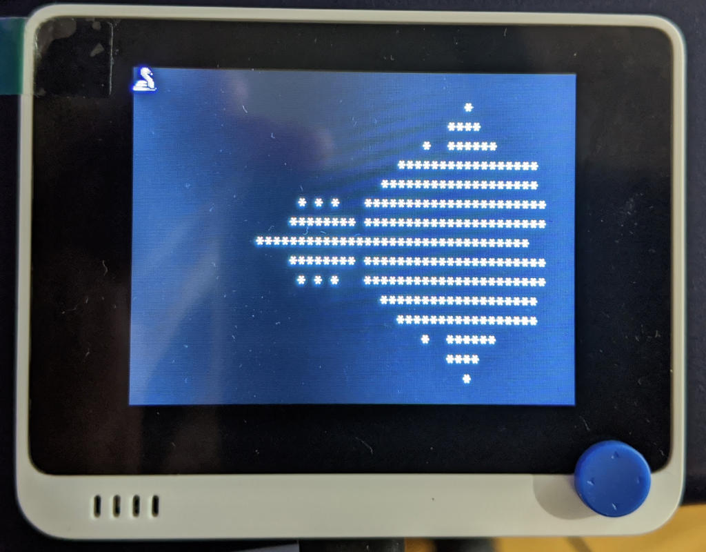
  • … although you can (and I verified this in a live demo at a user group) use a Wio Terminal as a tiny HMI (Human Machine Interface) USB display for Linux machines

The Wio Terminal is a little too powerful to be thought of as a simple micro-controller platform, but not quite powerful enough to be a standalone general purpose computer. I wish I could find a great application for it, though.


This post is modified from the talk I gave to the Toronto Raspberry Pi Meetup group in December 2020: SeeedStudio Wio Terminal: Applications with the Raspberry Pi. Thanks to Chloe and all at SeeedStudio for sending it to me.

Seeed is the IoT hardware enabler providing services over 10 years that empower makers to realize their projects and products. Seeed offers a wide array of hardware platforms and sensor modules ready to be integrated with existing IoT platforms and one-stop PCB fabrication and PCB assembly service. Seeed Studio provides a wide selection of electronic parts including Arduino  Raspberry Pi and many different development board platforms  Especially the Grove System help engineers and makers to avoid jumper wires problems. Seeed Studio has developed more than 280 Grove modules covering a wide range of applications that can fulfill a variety of needs. 

https://www.seeedstudio.com/

Disclosure: SeedStudio sent me this unit free of charge.

Canaduino STM32 boards with MicroPython

Volker Forster at Universal Solder was kind enough to send me a couple of these boards for free when I asked about availability. By way of thanks, I’m writing this article about what’s neat about these micro-controller boards.

always neat packaging from Universal Solder

Can I just say how nicely packaged Universal Solder’s own or customized products are? They want it to get to you, and they want it to work.

I’d previously played around with Blue Pill and Black Pill boards with limited success. Yes, they’re cheap and powerful, but getting the toolchain to work reliably was so much work. So when I read about the WeAct STM32F411CEU6 board on the MicroPython forum, I knew they’d be a much better bet.

Canaduino Black Pill Carrier Board with STM32F411 (and battery) installed

Volker sent me two different things:

Let’s start with the STM32 Screw Terminal Adapter:

Canaduino Black Pill Carrier Board (front)

It’s a neat, solid board built on a black 1.6 mm thick PCB. Apart from the obvious screw terminals — essential for long-term industrial installations — it adds three handy features:

  • a real-time clock battery. If you’re using a micro-controller for data logging, an RTC battery helps you keep timestamps accurate even if the device loses power.
  • mounting holes! This may seem a small thing, but if you can mount your micro-controller solidly, your project will look much more professional and last longer too.
  • A 6–30 V DC regulator. Connect this voltage between Vin and GND and the regulator will keep the board happy. From the helpful graph on the back of the board, it doesn’t look as if things start getting efficient until around 12 V, but it’s really nice to have a choice.
Canaduino Black Pill Carrier Board (back)

I made a little slip-case for this board so it wouldn’t short out on the workbench. The project is here: Canaduino STM32 Screw Terminal board tray and you can download a snapshot here:

The boards themselves are pretty neat:

two STM32F411 Black Pill boards from Canaduino

Gone are the lumpy pin headers of the earlier Blue and Black Pill boards, replaced by tactile switches. The iffy micro USB connectors are replaced by much more solid USB C connectors. According to STM32-base, the STM32F411 has:

  • 100 MHz ARM Cortex-M4 core. This brings fast (single-precision) floating point so you don’t have to fret over integer maths
  • 512 K Flash, 128 K RAM. MicroPython runs in this, but more flash is always helpful
  • Lots of digital and analogue I/O, including a 12-bit ADC
  • A user LED and user input switch.

About the only advanced features it’s missing are a true RNG, a DAC for analogue outputs, and WiFi. But on top of all this, Volker added:

the all-important 128 Mbit flash chip (and capacitor) fitted by Universal Solder

128 Mbit of Flash! This gives the board roughly 16 MB of storage that, when used with MicroPython, appears as a small USB drive for your programs and data. I found I was able to read the ADC more than 22,000 times/second under MicroPython, so who needs slow-to-deploy compiled code?

STM32F411 board pinout
board pinout from STM32F4x1 MiniF4 / WeAct Studio 微行工作室 出品.
Avoid A4-A7 if you’re using a flash chip.

Building and Installing MicroPython

This is surprisingly easy. You’ll need to install the gcc-arm-none-eabi compiler set before you start, but following the instructions at mcauser/WEACT_F411CEU6: MicroPython board definition for the WeAct STM32F411CEU6 board will get you there.

I had to run make a couple of times before it would build, but it built and installed quickly. This board doesn’t take UF2 image files that other boards use, so the installation is a little more complicated than other. But it works!

Once flashed, you should have a USB device with two important MicroPython files on it: boot.py and main.py. boot.py is best left alone, but main.py can be used for your program. I’m going into more details in a later article, but how about replacing the main.py program with the fanciest version if Blink you ever saw:

# main.py -- fancy Blink (scruss, 2020-05)

from pyb import LED
from machine import Timer
tim = Timer(-1)
tim.init(period=1000, mode=Timer.PERIODIC,
         callback=lambda t: LED(1).toggle())

None of that blocking delay() nonsense: we’re using a periodic timer to toggle the user LED every second!

debugging the mystery huge potentiometer using two ADC channels

I’m really impressed with the Universal Solder-modified board as an experimentation/discovery platform. MicroPython makes development and testing really quick and easy.

[and about the mystery huge potentiometer: it’s a Computer Instruments Corporation Model 206-IG multi-turn, multi-track potentiometer I picked up from the free table at a nerd event. I think it’s a 1950s (so Servo-control/Cybernetics age) analogue equivalent of a shaft encoder, looking at the patent. Best I can tell is that each pot (there are two, stacked, with precision bearings) appears to have two 120° 10k ohm sweep tracks offset 90° to one another. The four wipers are labelled -COS, -SIN, +COS and +SIN. If anyone knows more about the thing, let me know!]