This is a mini celebratory post to say that I’ve fixed the database encoding problems on this blog. It looks like I will have to go through the posts manually to correct the errors still, but at least I can enter, store and display UTF-8 characters as expected.
“? µ ° × — – ½ ¾ £ é?êè”, he said with some relief.
Postmortem: For reasons I cannot explain or remember, the database on this blog flipped to an archaic character set: latin1, aka ISO/IEC 8859-1. A partial fix was effected by downloading the entire site’s database backup, and changing all the following references in the SQL:
For additional annoyance, the entire SQL dump was too big to load back into phpmyadmin, so I had to split it by table. Thank goodness for awk!
#!/usr/bin/awk -f

BEGIN {
    outfile = "nothing.sql";
}

/^# Table: / {
    # very special comment in WP backup that introduces a new table
    # last field is table_name,
    # which we use to create table_name.sql
    t = $NF
    gsub(/`/, "", t);
    outfile = t ".sql";
}

{
    print > outfile;
}
The data still appears to be confused. For example, in the post Compose yourself, Raspberry Pi!, what should appear as “That little key marked “Compose”” appears as “That little key marked “Composeâ€Â”. This isn’t a straight conversion of one character set to another. It appears to have been double-encoded, and wrongly too.
Still, at least I can now write again and have whatever new things I make turn up the way I like. Editing 20 years of blog posts awaits … zzz
My OpenProcessing demo “autumn in canada”, redone as a NAPLPS playback file. Yes, it would have been nice to have outlined leaves, but I’ve only got four colours to play with that are vaguely autumnal in NAPLPS’s limited 2-bit RGB.
NAPLPS — an almost-forgotten videotex vector graphics format with a regrettable pronunciation (/nap-lips/, no really) — was really hard to create. Back in the early days when it was a worthwhile Canadian initiative called Telidon (see Inter/Access’s exhibit Remember Tomorrow: A Telidon Story) it required a custom video workstation costing $$$$$$. It got cheaper by the time the 1990s rolled round, but it was never easy and so interest waned.
I don’t claim what I made is particularly interesting:
suspiciously canadian
but even decoding the tutorial and standards material was hard. NAPLPS made heavy use of bitfields interleaved and packed into 7 and 8-bit characters. It was kind of a clever idea (lower resolution data could be packed into fewer bytes) but the implementation is quite unpleasant.
A few of the references/tools/resources I relied on:
The 1983 BYTE Magazine article series NAPLPS: A New Standard for Text and Graphics. Also long and needlessly wordy, with digressions into extensions that were never implemented. Contains a commented byte dump of an image that explains most concepts by example
John Durno has spent years recovering Telidon / NAPLPS works. He has published many useful resources on the subject
Here’s the fragment of code I wrote to generate the NAPLPS:
#!/usr/bin/env python3
# -*- coding: utf-8 -*-
# draw a disappointing maple leaf in NAPLPS - scruss, 2023-09

# stylized maple leaf polygon, quite similar to
# the coordinates used in the Canadian flag ...
maple = [
    [62, 2],
    [62, 35],
    [94, 31],
    [91, 41],
    [122, 66],
    [113, 70],
    [119, 90],
    [100, 86],
    [97, 96],
    [77, 74],
    [85, 114],
    [73, 108],
    [62, 130],
    [51, 108],
    [39, 114],
    [47, 74],
    [27, 96],
    [24, 86],
    [5, 90],
    [11, 70],
    [2, 66],
    [33, 41],
    [30, 31],
    [62, 35],
]


def colour(r, g, b):
    # r, g and b are limited to the range 0-3
    return chr(0o74) + chr(
        64
        + ((g & 2) << 4)
        + ((r & 2) << 3)
        + ((b & 2) << 2)
        + ((g & 1) << 2)
        + ((r & 1) << 1)
        + (b & 1)
    )


def coord(x, y):
    # if you stick with 256 x 192 integer coordinates this should be okay
    xsign = 0
    ysign = 0
    if x < 0:
        xsign = 1
        x = x * -1
        x = ((x ^ 255) + 1) & 255
    if y < 0:
        ysign = 1
        y = y * -1
        y = ((y ^ 255) + 1) & 255
    return (
        chr(
            64
            + (xsign << 5)
            + ((x & 0xC0) >> 3)
            + (ysign << 2)
            + ((y & 0xC0) >> 6)
        )
        + chr(64 + ((x & 0x38)) + ((y & 0x38) >> 3))
        + chr(64 + ((x & 7) << 3) + (y & 7))
    )


f = open("maple.nap", "w")
f.write(chr(0x18) + chr(0x1B))  # preamble

f.write(chr(0o16))  # SO: into graphics mode

f.write(colour(0, 0, 0))  # black
f.write(chr(0o40) + chr(0o120))  # clear screen to current colour

f.write(colour(3, 0, 0))  # red

# *** STALK ***
f.write(
    chr(0o44) + coord(maple[0][0], maple[0][1])
)  # point set absolute
f.write(
    chr(0o51)
    + coord(maple[1][0] - maple[0][0], maple[1][1] - maple[0][1])
)  # line relative

# *** LEAF ***
f.write(
    chr(0o67) + coord(maple[1][0], maple[1][1])
)  # set polygon filled
# append all the relative leaf vertices
for i in range(2, len(maple)):
    f.write(
        coord(
            maple[i][0] - maple[i - 1][0], maple[i][1] - maple[i - 1][1]
        )
    )

f.write(chr(0x0F) + chr(0x1A))  # postamble
f.close()
There are a couple of perhaps useful routines in there:
colour(r, g, b) spits out the code for two bits per component RGB. Inputs are limited to the range 0–3 without error checking
coord(x, y) converts integer coordinates to a NAPLPS output stream. Best limited to a 256 × 192 size. Will also work with positive/negative relative coordinates.
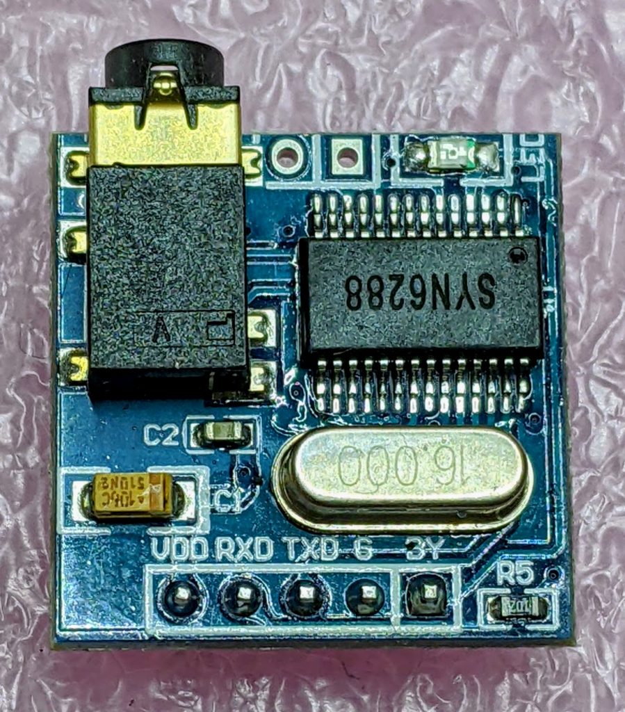
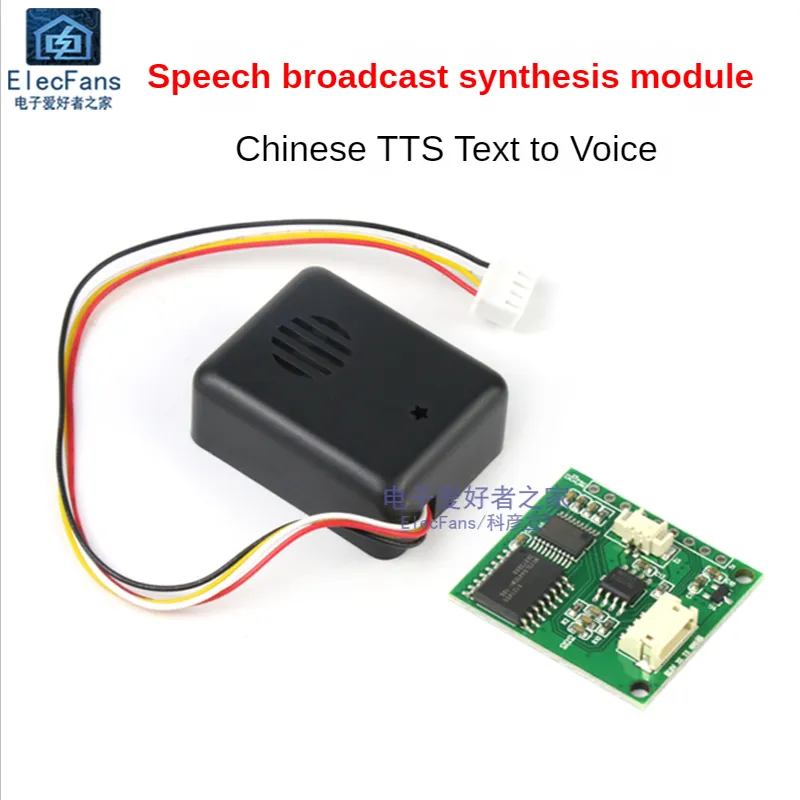
After remarkable success with the SYN-6988 TTS module, then somewhat less success with the SYN-6658 and other modules, I didn’t hold out much hope for the YuTone SYN-6288, which – while boasting a load of background tunes that could play over speech – can only convert Chinese text to speech
The wiring is similar to the SYN-6988: a serial UART connection at 9600 baud, plus a Busy (BY) line to signal when the chip is busy. The serial protocol is slightly more complicated, as the SYN-6288 requires a checksum byte at the end.
As I’m not interested in the text-to-speech output itself, here’s a MicroPython script to play all of the sounds:
# very crude MicroPython demo of SYN6288 TTS chip
# scruss, 2023-07
import machine
import time

### setup device
ser = machine.UART(
    0, baudrate=9600, bits=8, parity=None, stop=1
)  # tx=Pin(0), rx=Pin(1)

busyPin = machine.Pin(2, machine.Pin.IN, machine.Pin.PULL_UP)


def sendspeak(u2, data, busy):
    # modified from https://github.com/TPYBoard/TPYBoard_lib/
    # u2 = UART(uart, baud)
    eec = 0
    buf = [0xFD, 0x00, 0, 0x01, 0x01]
    # buf = [0xFD, 0x00, 0, 0x01, 0x79]  # plays with bg music 15
    buf[2] = len(data) + 3
    buf += list(bytearray(data, "utf-8"))
    for i in range(len(buf)):
        eec ^= int(buf[i])
    buf.append(eec)
    u2.write(bytearray(buf))
    while busy.value() != True:
        # wait for busy line to go high
        time.sleep_ms(5)
    while busy.value() == True:
        # wait for it to finish
        time.sleep_ms(5)


for s in "abcdefghijklmnopqrstuvwxy":
    playstr = "[v10][x1]sound" + s
    print(playstr)
    sendspeak(ser, playstr, busyPin)
    time.sleep(2)

for s in "abcdefgh":
    playstr = "[v10][x1]msg" + s
    print(playstr)
    sendspeak(ser, playstr, busyPin)
    time.sleep(2)

for s in "abcdefghijklmno":
    playstr = "[v10][x1]ring" + s
    print(playstr)
    sendspeak(ser, playstr, busyPin)
    time.sleep(2)
Each sound starts and stops with a very loud click, and the sound quality is not great. I couldn’t get a good recording of the sounds (some of which of which are over a minute long) as the only way I could get reliable audio output was through tiny headphones. Any recording came out hopelessly distorted:
I’m not too disappointed that this didn’t work well. I now know that the SYN-6988 is the good one to get. It also looks like I may never get to try the XFS5152CE speech synthesizer board: AliExpress has cancelled my shipment for no reason. It’s supposed to have some English TTS function, even if quite limited.
Here’s the auto-translated SYN-6288 manual, if you do end up finding a use for the thing
Yup, it’s another “let’s wire up a SYN6988 board” thing, this time for MMBasic running on the Armmite STM32F407 Module (aka ‘Armmite F4’). This board is also known as the BLACK_F407VE, which also makes a nice little MicroPython platform.
Uh, let’s not dwell too much on how the SYN6988 seems to parse 19:51 as “91 minutes to 20” …
Wiring
SYN6988
Armmite F4
RX
PA09 (COM1 TX)
TX
PA10 (COM1 RX)
RDY
PA08
your choice of 3.3 V and GND connections, of course
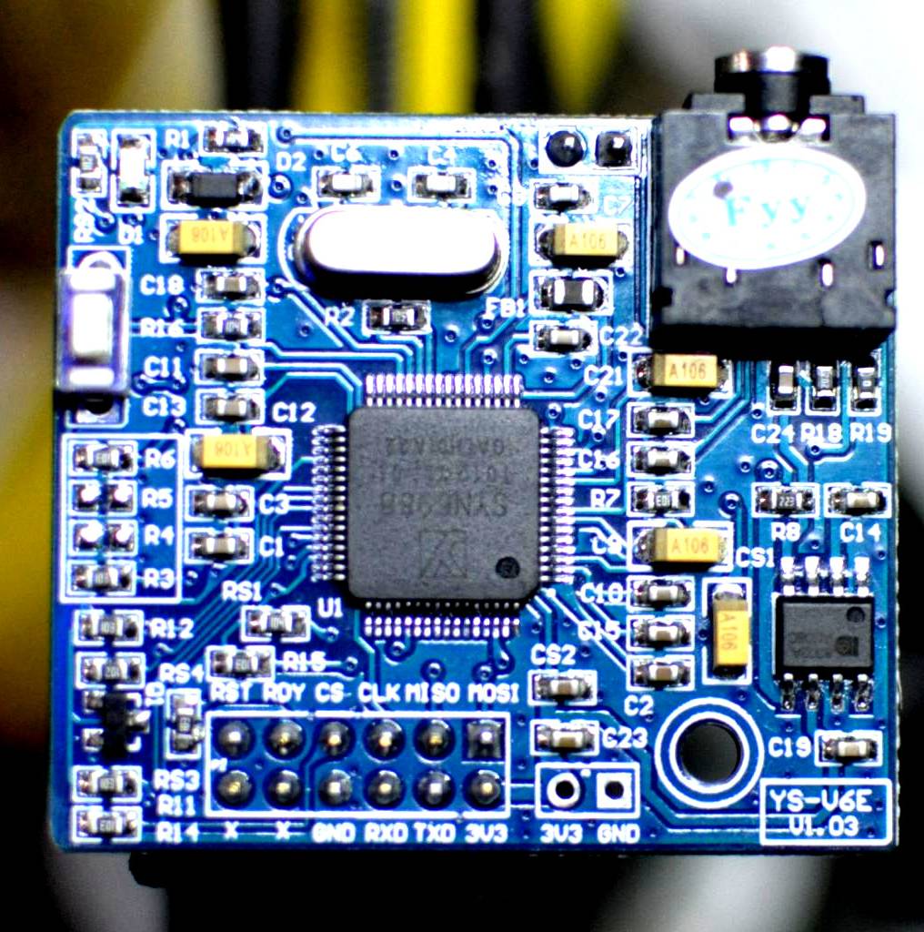
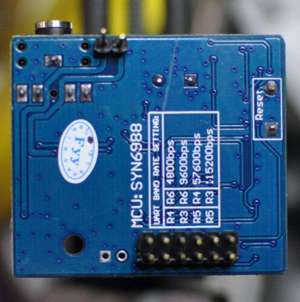
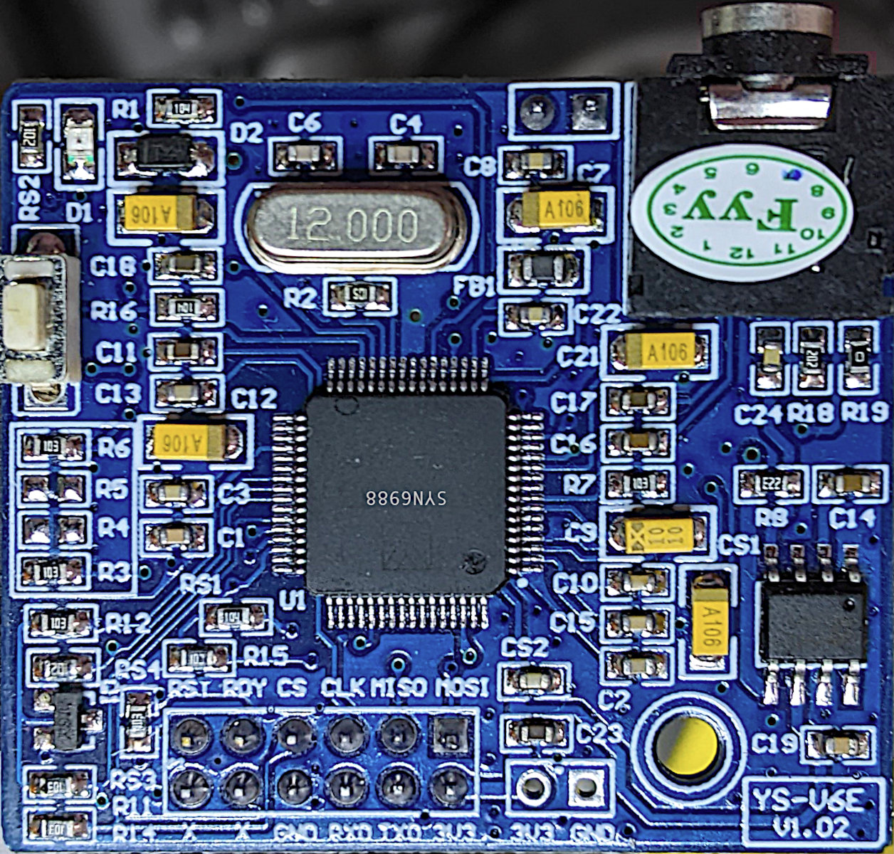
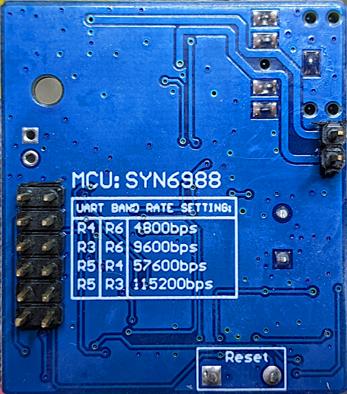
Yes, I know it says it’s an XFS5152, but I got a SYN6988 and it seems to be about as reliable a source as one can find. The board is marked YS-V6E-V1.03, and even mentions SYN6988 on the rear silkscreen:
Code
REM                 SYN6988 speech demo - MMBasic / Armmite F4
REM                 scruss, 2023-07

OPEN "COM1:9600" AS #5
REM                 READY line on PA8
SETPIN PA8, DIN, PULLUP

REM    you can ignore font/text commands
CLS
FONT 1
TEXT 0,15,"[v1]Hello - this is a speech demo."
say("[v1]Hello - this is a speech demo.")
TEXT 0,30,"[x1]soundy[d]"
say("[x1]soundy[d]"): REM    chimes
TEXT 0,45,"The time is "+LEFT$(TIME$,5)+"."
say("The time is "+LEFT$(TIME$,5)+".")
END

SUB say(a$)
  LOCAL dl%,maxlof%
  REM     data length is text length + 2 (for the 1 and 0 bytes)
  dl%=2+LEN(a$)
  maxlof%=LOF(#5)
  REM     SYN6988 simple data packet
  REM      byte  1 : &HFD
  REM      byte  2 : data length (high byte)
  REM      byte  3 : data length (low byte)
  REM      byte  4 : &H01
  REM      byte  5 : &H00
  REM      bytes 6-: ASCII string data
  PRINT #5, CHR$(&hFD)+CHR$(dl%\256)+CHR$(dl% MOD 256)+CHR$(1)+CHR$(0)+a$;
  DO WHILE LOF(#5)<maxlof%
  REM       pause while sending text
    PAUSE 5
  LOOP
  DO WHILE PIN(PA8)<>1
    REM       wait until RDY is high
    PAUSE 5
  LOOP
  DO WHILE PIN(PA8)<>0
    REM       wait until SYN6988 signals READY
    PAUSE 5
  LOOP
END SUB
The other week’s success with the SYN6988 TTS chip was not repeated with three other modules I ordered, alas. Two of them I couldn’t get a peep out of, the other didn’t support English text-to-speech.
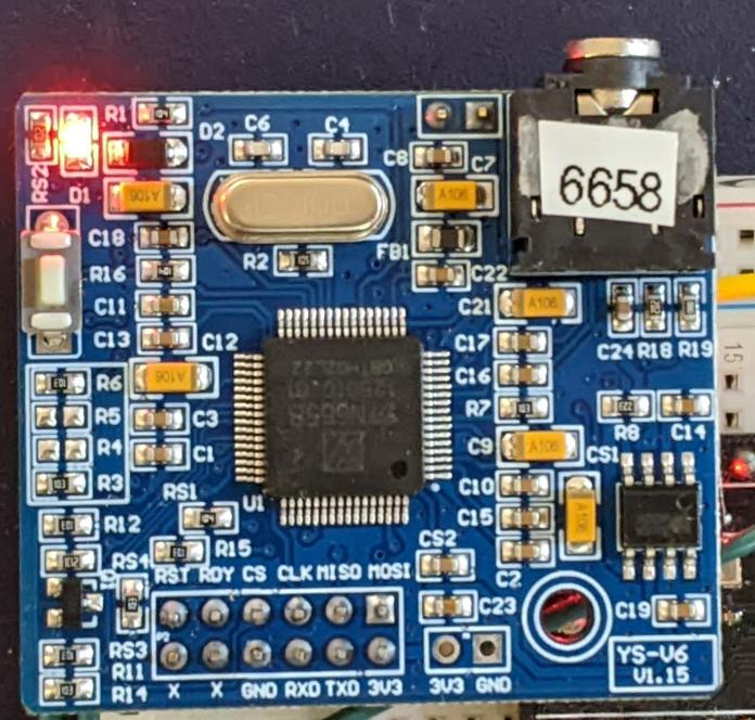
SYN6658
This one looks remarkably like the SYN6988:
Yes, I added the 6658 label so I could tell the boards apart
Apart from the main chip, the only difference appears to be that the board’s silkscreen says YS-V6 V1.15 where the SYN6988’s said YS-V6E V1.02.
To be fair to YuTone (the manufacturer), they claim this only supports Chinese as an input language. If you feed it English, at best you’ll get it spelling out the letters. It does have quite a few amusing sounds, though, so at least you can make it beep and chime. My MicroPython library for the VoiceTX SYN6988 text to speech module can drive it as far as I understand it.
I’ve still got a SYN6288 to look at, plus a XFS5152CE TTSthat’s in the mail that may or may not be in the mail. The SYN6988 is the best of the bunch so far.
I have a bunch of other boards on order to see if the other chips (SYN6288, SYN6658, XF5152) work in the same way. I really wonder which I’ll end up receiving!
Update (2023-07-09): Got the SYN6658. It does not support English TTS and thus is not recommended. It does have some cool sounds, though.
Embedded Text Command Sound Table
The github repo references Embedded text commands, but all of the sound references were too difficult to paste into a table there. So here are all of the ones that the SYN-6988 knows about:
Name is the string you use to play the sound, eg: [x1]sound101
Alias is an alternative name by which you can call some of the sounds. This is for better compatibility with the SYN6288 apparently. So [x1]sound101 is exactly the same as specifying [x1]sounda
Type is the sound description from the manual. Many of these are blank
Link is a playable link for a recording of the sound.
I’ve had one of these cheap(ish – $15) sound modules from AliExpress for a while. I hadn’t managed to get much out of it before, but I poked about at it a little more and found I was trying to drive the wrong chip. Aha! Makes all the difference.
Sensitive listener alert! There is a static click midway through. I edited out the clipped part, but it’s still a little jarring. It would always do this at the same point in playback, for some reason.
The only Pythonish code I could find for these chips was meant for the older SYN6288 and MicroPython (syn6288.py). I have no idea what I’m doing, but with some trivial modification, it makes sound.
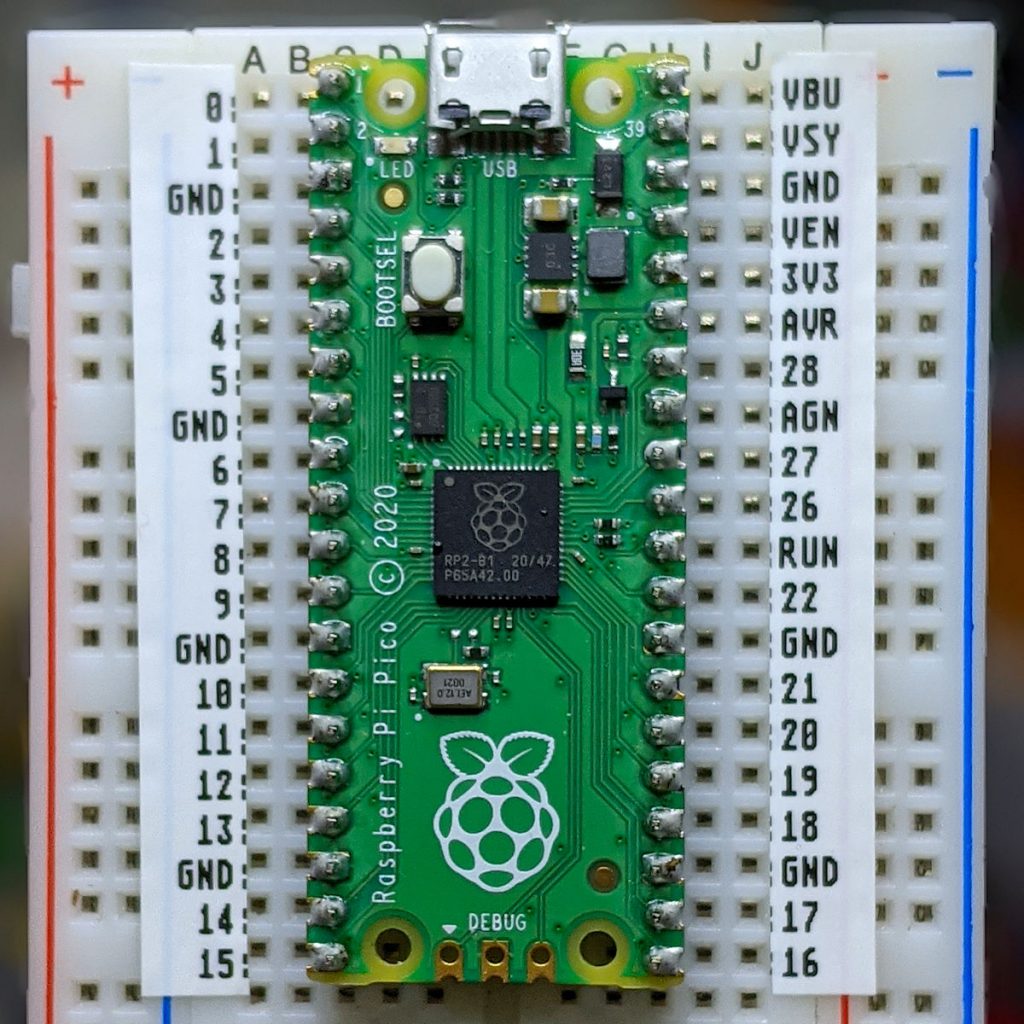
I used the simple serial UART connection: RX -> TX, TX -> RX, 3V3 to 3V3 and GND to GND. My board is hard-coded to run at 9600 baud. I used the USB serial adapter that came with the board.
Here’s the code that read that text:
#!/usr/bin/env python3
# -*- coding: utf-8 -*-

import serial
import time

# NB via MicroPython and old too! Also for a SYN6288, which I don't have
# nabbed from https://github.com/TPYBoard/TPYBoard_lib/

def sendspeak(port, data):
    eec = 0
    buf = [0xFD, 0x00, 0, 0x01, 0x01]
    buf[2] = len(data) + 3
    buf += list(bytearray(data, encoding='utf-8'))
    for i in range(len(buf)):
        eec ^= int(buf[i])
    buf.append(eec)
    port.write(bytearray(buf))

ser = serial.Serial("/dev/ttyUSB1", 9600)
sendspeak(ser, "[t5]I like to think [p100](it [t7]has[t5] to be!)[p100] of a cybernetic ecology [p100]where we are free of our labors and joined back to nature, [p100]returned to our mammal brothers and sisters, [p100]and all watched over by machines of loving grace")
time.sleep(8)
ser.close()
This code is bad. All I did was prod stuff until it stopped not working. Since all I have to work from includes a datasheet in Chinese (from here: ??????-SYN6988???TTS????) there’s lots of stuff I could do better. I used the tone and pause tags to give the reading a little more life, but it’s still a bit flat. For $15, though, a board that makes a fair stab at reading English is not bad at all. We can’t all afford vintage DECtalk hardware.
The one thing I didn’t do is used the SYN6988’s Busy/Ready line to see if it was still busy reading. That means I could send it text as soon as it was ready, rather than pausing for 8 seconds after the speech. This refinement will come later, most likely when I port this to MicroPython.
It’s now possible to build and run the DECtalk text to speech system on Linux. It even builds under emscripten, enabling DECtalk for Web in your browser. You too can annoy everyone within earshot making it prattle on about John Madden.
But DECTalk can sing! Because it’s been around so long, there are huge archives of songs in DECtalk format out there. The largest archive is at THE FLAME OF HOPE website, under the Dectalk section.
Building DECtalk songs isn’t easy, especially for a musical numpty like me. You need a decent grasp of music notation, phonemic/phonetic markup and patience with DECtalk’s weird and ancient text formats.
DECtalk phonemes
While DECtalk can accept text and turn it into a fair approximation of spoken English, for singing you have to use phonemes. Let’s say we have a solfège-ish major scale:
DECtalk uses a variant on the ARPABET convention to represent IPA symbols as ASCII text. The initial consonant sounds remain as you might expect: D, R, M, F, S, L and T. The vowel sounds, however, are much more complex. This will give us a DECtalk-speakable phrase:
[dow rey miy faa sow laa tiy dow].
Note the opening and closing brackets and the full stop at the end. The brackets introduce phonemes, and the full stop tells DECtalk that the text is at an end. Play it in the DECtalk for Web window and be unimpressed: while the pitch changes are non-existent, the sounds are about right.
If you want to have a rough idea of what the phonemes in a phrase might be, you can use DECtalk’s :log phonemes option. You might still have to massage the input and output a bit, like using sed to remove language codes:
say -l us -pre '[:log phonemes on]' -post '[:log phonemes off]' -a "doe ray me fah so lah tea doe" | sed 's/us_//g;'
d ' ow  r ' ey  m iy  f ' aa) s ow  ll' aa  t ' iy  d ' ow.
Music notation
To me — a not very musical person — staff notation looks like it was designed by a maniac. A more impractical system to indicate arrangement of notes and their durations I don’t think I could come up with: and yet we’re stuck with it.
DECtalk uses a series of numbered pitches plus durations in milliseconds for its singing mode. The notes (1–37) correspond to C2 to C5. If you’re familiar with MIDI note numbers, DECtalk’s 1–37 correspond to MIDI note numbers 36–72. This is how DECtalk’s pitch numbers would look as major scales on the treble clef:
The entire singing range of DECtalk as a C Major scale, from note 1 (C2, 65.4 Hz) to note 37 (C5, 523.4 Hz)
I’m not sure browsers can play MIDI any more, but here you go (doremi-abc.mid):
and since I had to learn abc notation to make these noises, here is the source:
%abc-2.1
X:1
T:Do Re Mi
C:Trad.
M:4/4
L:1/4
Q:1/4=120
K:C
%1
C,, D,, E,, F,,| G,, A,, B,, C,| D, E, F, G,| A, B, C D| E F G A| B c z2 |]
w:do re mi fa sol la ti do re mi fa sol la ti do re mi fa sol la ti do
Each element of a DECtalk song takes the following form:
phoneme <duration, pitch number>
The older DTC-03 manual hints that it takes around 100 ms for DECtalk to hit pitch, so for each ½ second utterance (or quarter note at 120 bpm, ish), I split it up as:
100 ms of the initial consonant;
337 ms of the vowel sound;
63 ms of pause (which has the phoneme code “_”). Pauses don’t need pitch numbers, unless you want them to preempt DECtalk’s pitch-change algorithm.
So the three lowest notes in the major scale would sing as:
You can paste that into the DECtalk browser window, or run the following from the command line on Linux:
say -pre '[:PHONE ON]' -a '[d<100,1>ow<337,1>_<63>r<100,3>ey<337,3>_<63>m<100,5>iy<337,5>_<63>f<100,6>aa<337,6>_<63>s<100,8>ow<337,8>_<63>l<100,10>aa<337,10>_<63>t<100,12>iy<337,12>_<63>d<100,13>ow<337,13>_<63>r<100,15>ey<337,15>_<63>m<100,17>iy<337,17>_<63>f<100,18>aa<337,18>_<63>s<100,20>ow<337,20>_<63>l<100,22>aa<337,22>_<63>t<100,24>iy<337,24>_<63>d<100,25>ow<337,25>_<63>r<100,27>ey<337,27>_<63>m<100,29>iy<337,29>_<63>f<100,30>aa<337,30>_<63>s<100,32>ow<337,32>_<63>l<100,34>aa<337,34>_<63>t<100,36>iy<337,36>_<63>d<100,37>ow<337,37>_<63>].'
It sounds like this:
Singing a scale is hardly singing a tune, but hey, you were warned that this was a terrible guide at the outset. I hope I’ve given you a start on which you can build your own songs.
(One detail I haven’t tried yet: the older DTC-03 manual hints that singing notes can take Hz values instead of pitch numbers, and apparently loses the vibrato effect. It’s not that hard to convert from a note/octave to a frequency. Whether this still works, I don’t know.)
This post from Patrick Perdue suggested to me I had to dig into the Hz value substitution because the results are so gloriously awful. Of course, I had to write a Perl regex to make the conversions from DECtalk 1–37 sung notes to frequencies from 65–523 Hz:
(as one does). So the sung scale ends up as this non-vibrato text:
say -pre '[:PHONE ON]' -a '[d<100,65>ow<337,65>_<63>r<100,73>ey<337,73>_<63>m<100,82>iy<337,82>_<63>f<100,87>aa<337,87>_<63>s<100,98>ow<337,98>_<63>l<100,110>aa<337,110>_<63>t<100,123>iy<337,123>_<63>d<100,131>ow<337,131>_<63>r<100,147>ey<337,147>_<63>m<100,165>iy<337,165>_<63>f<100,175>aa<337,175>_<63>s<100,196>ow<337,196>_<63>l<100,220>aa<337,220>_<63>t<100,247>iy<337,247>_<63>d<100,262>ow<337,262>_<63>r<100,294>ey<337,294>_<63>m<100,330>iy<337,330>_<63>f<100,349>aa<337,349>_<63>s<100,392>ow<337,392>_<63>l<100,440>aa<337,440>_<63>t<100,494>iy<337,494>_<63>d<100,523>ow<337,523>_<63>].'
That doesn’t sound as wondrously terrible as it should, most probably as they are very small differences between each sung word. So how about we try something better? Like the refrain from The Turtles’ Happy Together, as posted on TheFlameOfHope:
I can’t believe I’m having to write this article again. Back in 2004, I picked up an identical model of typewriter on Freecycle, also complete with the parallel printer option board. The one I had back then had an incredible selection of printwheels. And I gave it all away! Aaargh! Why?
Last month, I ventured out to a Value Village in more affluent part of town. On the shelf for $21 was a familiar boxy shape, another Wheelwriter 10 Series II Typewriter model 6783. This one also has the printer option board, but it only has one printwheel, Prestige Elite. It powered on enough at the test rack enough for me to see it mostly worked, so I bought it.
Once I got it home, though, I could see it needed some work. The platen was covered in ink and correction fluid splatters. Worse, the carriage would jam in random places. It was full of dust and paperclips. But the printwheel did make crisp marks on paper, so it was worth looking at a repair.
Note that there are lots of electronics projects — such as tofergregg/IBM-Wheelwriter-Hack: Turning an IBM Wheelwriter into a unique printer — that use an Arduino or similar to drive the printer. This is not that (or those). Here I’m using the Printer Option board plus a USB to Parallel cable. There’s almost nothing out there about how these work.
Connecting the printer
You’ll need a USB to Parallel adapter, something like this: StarTech 10 ft USB to Parallel Printer Adapter – M/M. You need the kind with the big Centronics connector, not the 25-pin D-type. My one (old) has a chunky plastic case that won’t fit into the port on the Wheelwriter unless you remove part of the cable housing. On my Linux box, the port device is /dev/usb/lp0. You might want to add yourself to the lp group so you can send data to the printer without using sudo:
sudo adduser user lp
The Wheelwriter needs to be switched into printer mode manually by pressing the Code + Printer Enable keys.
Printer Codes
As far as I can tell, the Wheelwriter understands a subset of IBM ProPrinter codes. Like most simple printers, most control codes start with an Esc character (ASCII 27). Lines need to end with both a Carriage Return (ASCII 13) and newline (ASCII 10). Sending only CRs allows overprinting, while sending only newlines gives stair-step output.
The codes I’ve found to work so far are:
Emphasized printing — Esc E
Cancel emphasized printing — Esc F (double strike printing [Esc G, Esc H] might also work, but I haven’t tried them)
Continuous underscore — Esc – 1
Cancel continuous underscore — Esc – 0 (technically, these are Esc – n, where n = ASCII 1 or 0, not character “1” or “0”. But the characters seem to work, too)
7/72″ inch line spacing — Esc 1
Set text line spacing to n / 72″ units — Esc A n (this one really matters: if you send “6” (ASCII 66) instead of 6, you’ll get 66/72 = 11/12″ [= 28.3 mm] line spacing instead of the 1/12″ [= 2.1 mm] you expected)
Start text line spacing — Esc 2
Text functions such as italics and extended text aren’t possible with a daisywheel printer. You can attempt dot-matrix graphics using full stops and micro spacing, but I don’t want to know you if you’d try.
Sending codes from the command line
echo is about the simplest way of doing it. Some systems provide an echo built-in that doesn’t support the -e (interpret special characters) and -n (don’t send newline) options. You may have to call /usr/bin/echo instead.
To set the line spacing to a (very cramped) 1/12″ [= 2.1 mm] and print a horizontal line of dots and a vertical line of dots, both equally spaced (if you’re using Prestige Elite):
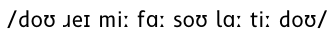
IBM daisywheels typically can’t represent the whole ASCII character set. Here’s what an attempt to print codes 33 to 126 in Prestige Elite looks like:
The following characters are missing:
< > \ ^ ` { | } ~
So printing your HTML or Python is right out. FORTRAN, as ever, is safe.
Prestige Elite is a 12 character per inch font (“12 pitch”, or even “Elite” in typewriter parlance) that’s mostly been overshadowed by Courier (typically 10 characters per inch) in computer usage. This is a shame, as it’s a much prettier font.
Related, yet misc.
There’s very little out there about printing with IBM daisywheels. This is a dump of the stuff I’ve found that may help other people:
IBM didn’t make too many daisywheel printers. Two models were the 5216 Wheelprinter and 5223 Wheelprinter E, possibly intended for larger IBM machines. The 5216 Wheelprinter looks like it may use similar character codes. Here’s a (Printer Definition File?? An IBM thing, I think) for that printer that might help the interested: ibm5216_pdf
I don’t think I’ve had as much enjoyment for a piece of software for a very long time as I’ve had with BirdNET-Pi. It’s a realtime acoustic bird classification system for the Raspberry Pi. It listens through a microphone you place somewhere near where you can hear birds, and it’ll go off and guess what it’s hearing, using a cut-down version of the BirdNET Sound ID model. It does this 24/7, and saves the samples it hears. You can then go to a web page (running on the same Raspberry Pi) and look up all the species it has heard.
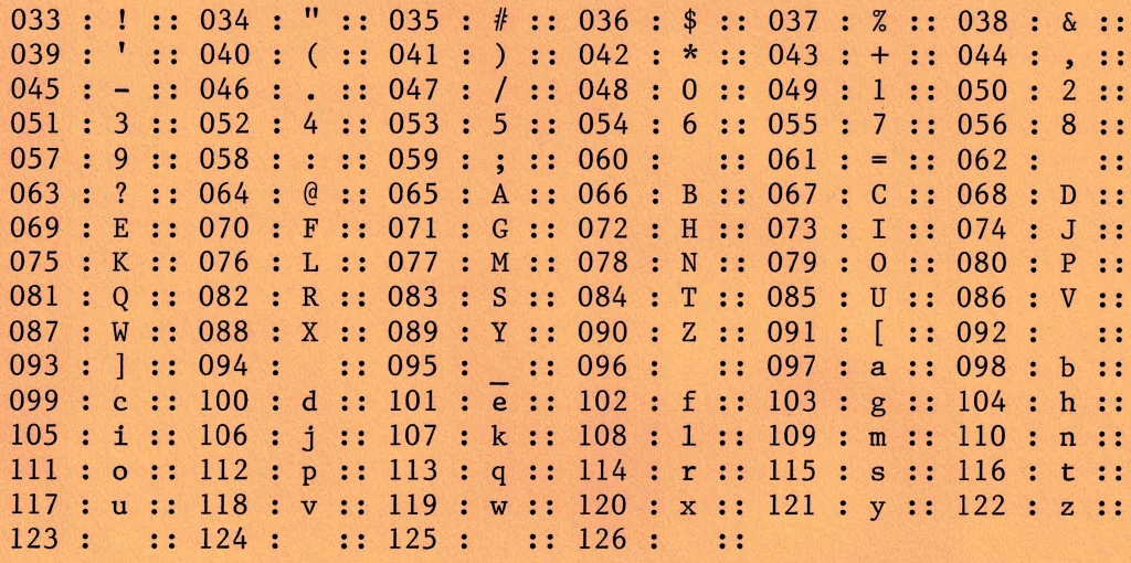
Our Garden
Not very impressive, kind of overgrown, in the wrong part of town. Small, too. But birds love it. At this time of year, it’s alive with birds. You can’t make them out, but there’s a pair of Rose-breasted Grosbeaks happily snacking near the top of the big tree. There are conifers next door too, so we get birds we wouldn’t expect.
We are next to two busy subway/train stations, and in between two schools. There’s a busy intersection nearby, too. Consequently, the background noise is horrendous
What I used
This was literally “stuff I had lying around”:
Raspberry Pi 3B+ (with power supply, case, thermostatic fan and SD card)
USB extension cable (this, apparently, is quite important to isolate the USB audio device from electrical noise)
Horrible cheap USB sound card: I paid about $2 for a “3d sound” thing about a decade ago. It records in mono. It works. My one is wrapped in electrical tape as the case keeps threatening to fall off, plus it has a hugely bright flashing LED that is annoying.
Desktop mic (circa 2002): before video became a thing, PCs had conferencing microphones. I think I got this one free with a PC over 20 years ago. It’s entirely unremarkable and is not an audiophile device. I stuck it out a back window and used a strip of gaffer tape to stop bugs getting in. It’s not waterproof, but it didn’t rain the whole week it was out the window.
I’ll put the recordings at the end of this post. Note, though, they’re noisy: Cornell Lab quality they ain’t.
What I learned
This is the first time that I’ve let an “AI” classifier model run with no intervention. If it flags some false positives, then it’s pretty low-stakes when it’s wrong. And how wrong did it get some things!
allegedly a Barred Owl, this is clearly a two-stroke leafblowerBlack-Billed Cuckoo? How about kids playing in the school yard?Emergency vehicles are Common Loons now, according to BirdNetPiPolice cars at 2:24 am are Eastern Screech-Owls. I wonder if we could use this classifier to detect over-policed, under-served neighbourhoods?Great Black-backed Gulls, or kids playing? The latterTurkey Vulture? How about a very farty two-stroke engine in a bicycle frame driving past? (This thing stinks out the street, blecch)
There are also false positive for Trumpeter Swans (local dog) and Tundra Swans (kids playing). These samples had recognizable voices, so I didn’t include them here.
The 30 positive species identifications
Many of these have a fairly loud click at the start of the sample, so mind your ears.
BirdNetPi doesn’t create combined spectrograms with audio as a single video file. What it does do is create an mp3 plus a PNG of the spectrogram. ffmpeg can make a nice not-too-large webm video for sharing:
as performed by the flite speech synthesizer and some shell scripts
The Computer’s First Christmas card
Not quite as good as having the late Prof. Morgan recite it to you himself — one of the few high points of my school experience — but you take what you can get in this economy.
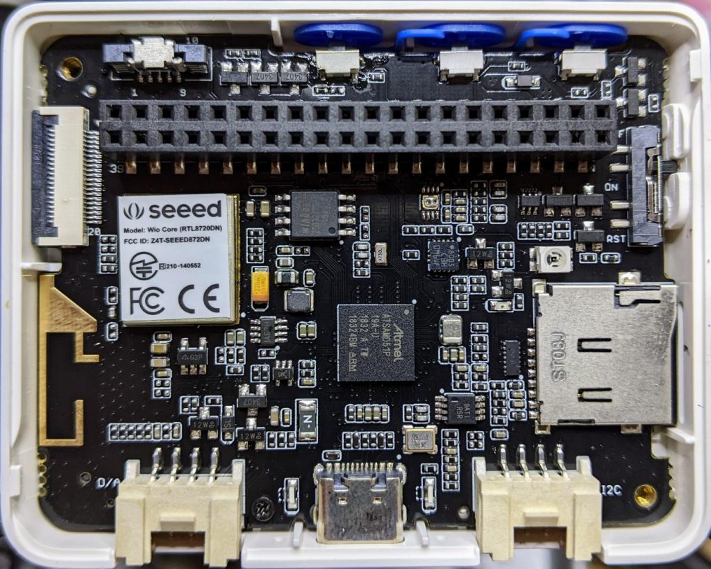
A while back, Seeed Studio sent me one of their Wio Terminal devices to review. It was pretty neat, but being limited to using Arduino to access all of it features was a little limiting. I still liked it, though, and wrote about it here: SeeedStudio Wio Terminal
Wio Terminal, doing a thing
There wasn’t any proper MicroPython support for the device as it used a MicroChip/Atmel SAMD51 ARM® Cortex®-M4 micro-controller. But since I wrote the review, one developer (robert-hh) has worked almost entirely solo to make SAMD51 and SAMD21 support useful in mainline MicroPython.
Hey! Development is still somewhere between “not quite ready for prime time” and “beware of the leopard”. MicroPython on the SAMD51 works remarkably well for supported boards, but don’t expect this to be beginner-friendly yet.
I thought I’d revisit the Wio Terminal and see what I could do using a nightly build (downloaded from Downloads – Wio Terminal D51R – MicroPython). Turns out, most of the board works really well!
What doesn’t work yet
Networking/Bluetooth – this is never going to be easy, especially with Seeed Studio using a separate RTL8720 SoC. It may not be entirely impossible, as previously thought, but so far, wifi support seems quite far away
RTC – this is a compile-time option, but isn’t available on the stock images. Not all SAMD51 boards have a separate RTC oscillator, and deriving the RTC from the system oscillator would be quite wobbly. RTC works now! It may even be possible to provide backup battery power and have it keep time when powered off. VBAT / PB03 / SPI_SCK is broken out to the 40-pin connector.
What does work
Display – ILI9341 320×240 px, RGB565 via SPI
Accelerometer – LIS3DHTR via I²C
Microphone – analogue
Speaker – more like a buzzer, but this little PWM speaker element does allow you to play sounds
Light Sensor – via analogue photo diode
IR emitter – PWM, not tied to any hardware protocol
Internal LED – a rather faint blue thing, but useful for low-key signalling
Micro SD Card – vi SPI. Works well with MicroPython’s built-in virtual file systems
Switches and buttons – three buttons on the top, and a five-way mini-joystick
I²C via Grove Connector – a second, separate I²C channel.
I’ll go through each of these here, complete with a small working example.
Inside the remarkably hard-to-open Wio Terminal
LED
Let’s start with the simplest feature: the tiny blue LED hidden inside the case. You can barely see this, but it glows out around the USB C connector on the bottom of the case.
MicroPython interfaces: machine.Pin, machine.PWM
Control pin: Pin(“LED_BLUE”) or Pin(15), or Pin(“PA15”): any one of these would work.
# MicroPython / Seeed Wio Terminal / SAMD51
# Wio-Terminal-LED.py - blink the internal blue LED
# scruss, 2022-10
# -*- coding: utf-8 -*-

from machine import Pin
from time import sleep_ms

led = Pin("LED_BLUE", Pin.OUT)  # or Pin(15) or Pin("PA15")

try:
    while True:
        led.value(not led.value())
        sleep_ms(1200)
except:
    led.value(0)  # turn it off if user quits
    exit()
IR LED
I don’t have any useful applications of the IR LED for device control, so check out Awesome MicroPython’s IR section for a library that would work for you.
# MicroPython / Seeed Wio Terminal / SAMD51
# Wio-Terminal-IR_LED.py - blink the internal IR LED
# scruss, 2022-10
# -*- coding: utf-8 -*-

# Hey! This is a completely futile exercise, unless you're able
# to see into the IR spectrum. But we're here to show you the pin
# specification to use. For actual useful libraries to do stuff with
# IR, take a look on https://awesome-micropython.com/#ir

# So this is a boring blink, 'cos we're keeping it short here.
# You might be able to see the LED (faintly) with your phone camera

from machine import Pin, PWM
from time import sleep_ms

ir = PWM(Pin("PB31"))  # "IR_CTL" not currently defined

try:
    while True:
        ir.duty_u16(32767)  # 50% duty
        ir.freq(38000)  # fast flicker
        sleep_ms(1200)
        ir.duty_u16(0)  # off
        sleep_ms(1200)
except:
    ir.duty_u16(0)  # turn it off if user quits
    exit()
Buttons
There are three buttons on top, plus a 5-way joystick on the front. Their logic is inverted, so they read 0 when pressed, 1 when not. It’s probably best to use machine.Signal with these to make operation more, well, logical.
Control pins: Pin(“BUTTON_3”) or Pin(92) or Pin(PC28) – top left; Pin(“BUTTON_2”) or Pin(91) or Pin(PC27) – top middle; Pin(“BUTTON_1”) or Pin(90) or Pin(PC26) – top right; Pin(“SWITCH_B”) or Pin(108) or Pin(PD12) – joystick left; Pin(“SWITCH_Y”) or Pin(105) or Pin(PD09) – joystick right; Pin(“SWITCH_U”) or Pin(116) or Pin(PD20) – joystick up; Pin(“SWITCH_X”) or Pin(104) or Pin(PD08) – joystick down; Pin(“SWITCH_Z”) or Pin(106) or Pin(PD10) – joystick button
# MicroPython / Seeed Wio Terminal / SAMD51
# Wio-Terminal-Buttons.py - test the buttons
# scruss, 2022-10
# -*- coding: utf-8 -*-

# using Signal because button sense is inverted: 1 = off, 0 = on
from machine import Pin, Signal
from time import sleep_ms

pin_names = [
    "BUTTON_3",  # Pin(92)  or Pin(PC28) - top left
    "BUTTON_2",  # Pin(91)  or Pin(PC27) - top middle
    "BUTTON_1",  # Pin(90)  or Pin(PC26) - top right
    "SWITCH_B",  # Pin(108) or Pin(PD12) - joystick left
    "SWITCH_Y",  # Pin(105) or Pin(PD09) - joystick right
    "SWITCH_U",  # Pin(116) or Pin(PD20) - joystick up
    "SWITCH_X",  # Pin(104) or Pin(PD08) - joystick down
    "SWITCH_Z",  # Pin(106) or Pin(PD10) - joystick button
]

pins = [None] * len(pin_names)
for i, name in enumerate(pin_names):
    pins[i] = Signal(Pin(name, Pin.IN), invert=True)

while True:
    for i in range(len(pin_names)):
        print(pins[i].value(), end="")
    print()
    sleep_ms(100)
Buzzer
A very quiet little PWM speaker.
MicroPython interfaces: machine.PWM
Control pin: Pin(“BUZZER”) or Pin(107) or Pin(“PD11”)
# MicroPython / Seeed Wio Terminal / SAMD51
# Wio-Terminal-Microphone.py - print values from the microphone
# scruss, 2022-10
# -*- coding: utf-8 -*-

from time import sleep_ms
from machine import ADC

mic = ADC("MIC")

while True:
    print([mic.read_u16()])
    sleep_ms(5)
Grove I²C Port
The Wio Terminal has two Grove ports: the one on the left (under the speaker port) is an I²C port. As I don’t know what you’ll be plugging in there, this example does a simple bus scan. You could make a, appalling typewriter if you really wanted.
# MicroPython / Seeed Wio Terminal / SAMD51
# Wio-Terminal-Grove-I2C.py - show how to connect on Grove I2C
# scruss, 2022-10
# -*- coding: utf-8 -*-

from machine import Pin, I2C

# NB: This doesn't do much of anything except list what's
# connected to the left (I²C) Grove connector on the Wio Terminal

i2c = I2C(3, scl=Pin("SCL1"), sda=Pin("SDA1"))
devices = i2c.scan()

if len(devices) == 0:
    print("No I²C devices connected to Grove port.")
else:
    print("Found these I²C devices on the Grove port:")
    for n, id in enumerate(devices):
        print(" device", n, ": ID", id, "(hex:", hex(id) + ")")
LIS3DH Accelerometer
This is also an I²C device, but connected to a different port (both logically and physically) than the Grove one.
Library: from MicroPython-LIS3DH, copy lis3dh.py to the Wio Terminal’s small file system. Better yet, compile it to mpy using mpy-cross to save even more space before you copy it across
# MicroPython / Seeed Wio Terminal / SAMD51
# Wio-Terminal-Accelerometer.py - test out accelerometer
# scruss, 2022-10
# -*- coding: utf-8 -*-
# based on
#  https://github.com/tinypico/tinypico-micropython/tree/master/lis3dh%20library

import lis3dh, time, math
from machine import Pin, I2C

i2c = I2C(4, scl=Pin("SCL0"), sda=Pin("SDA0"))
imu = lis3dh.LIS3DH_I2C(i2c)

last_convert_time = 0
convert_interval = 100  # ms
pitch = 0
roll = 0

# Convert acceleration to Pitch and Roll
def convert_accell_rotation(vec):
    x_Buff = vec[0]  # x
    y_Buff = vec[1]  # y
    z_Buff = vec[2]  # z

    global last_convert_time, convert_interval, roll, pitch

    # We only want to re-process the values every 100 ms
    if last_convert_time < time.ticks_ms():
        last_convert_time = time.ticks_ms() + convert_interval

        roll = math.atan2(y_Buff, z_Buff) * 57.3
        pitch = (
            math.atan2((-x_Buff), math.sqrt(y_Buff * y_Buff + z_Buff * z_Buff)) * 57.3
        )

    # Return the current values in roll and pitch
    return (roll, pitch)


# If we have found the LIS3DH
if imu.device_check():
    # Set range of accelerometer (can be RANGE_2_G, RANGE_4_G, RANGE_8_G or RANGE_16_G).
    imu.range = lis3dh.RANGE_2_G

    # Loop forever printing values
    while True:
        # Read accelerometer values (in m / s ^ 2).  Returns a 3-tuple of x, y,
        # z axis values.  Divide them by 9.806 to convert to Gs.
        x, y, z = [value / lis3dh.STANDARD_GRAVITY for value in imu.acceleration]
        print("x = %0.3f G, y = %0.3f G, z = %0.3f G" % (x, y, z))

        # Convert acceleration to Pitch and Roll and print values
        p, r = convert_accell_rotation(imu.acceleration)
        print("pitch = %0.2f, roll = %0.2f" % (p, r))

        # Small delay to keep things responsive but give time for interrupt processing.
        time.sleep(0.1)
Control Pins: Pin(“SD_SCK”), Pin(“SD_MOSI”), Pin(“SD_MISO”) for SD access. Pin(“SD_DET”) is low if an SD card is inserted, otherwise high
Library: copy sdcard.py from micropython-lib to the Wio Terminal’s file system.
Rather than provide a small canned example (there’s one here, if you must: Wio-Terminal-SDCard.py) here’s my boot.py startup file, showing how I safely mount an SD card if there’s one inserted, but keep booting even if it’s missing:
# boot.py - MicroPython / Seeed Wio Terminal / SAMD51

import sys

sys.path.append("/lib")

import machine
import gc
import os
import sdcard

machine.freq(160000000)  # fast but slightly jittery clock
gc.enable()

# mount SD card if there's one inserted
try:
    sd_detected = machine.Signal(
        machine.Pin("SD_DET", machine.Pin.IN),
        invert=True,
    )
    sd_spi = machine.SPI(
        6,
        sck=machine.Pin("SD_SCK"),
        mosi=machine.Pin("SD_MOSI"),
        miso=machine.Pin("SD_MISO"),
        baudrate=40000000,
    )
    sd = sdcard.SDCard(sd_spi, machine.Pin("SD_CS"))
    if sd_detected.value() == True:
        os.mount(sd, "/SD")
        print("SD card mounted on /SD")
    else:
        raise Exception("SD card not inserted, can't mount /SD")
except:
    print("SD card not found")
The Wio Terminal may have an XPT2046 resistive touch controller installed, but I haven’t been able to test it. There are LCD_XL, LCD_YU, LCD_XR and LCD_YD lines on the schematic that might indicate it’s there, though.
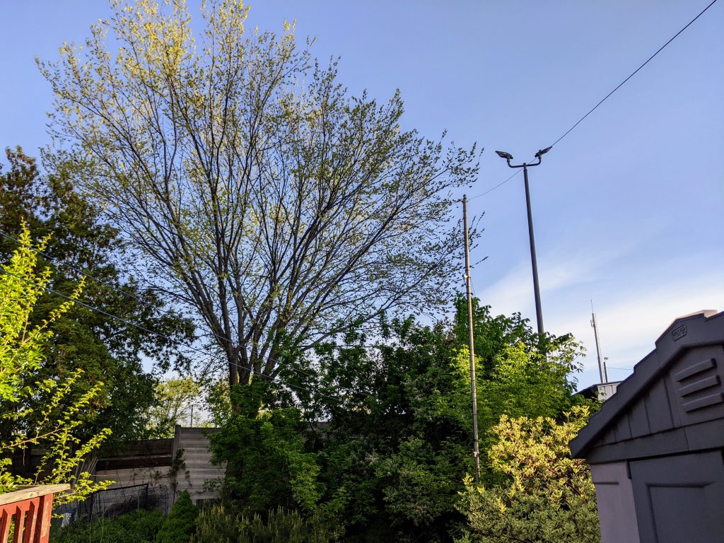
# MicroPython / Seeed Wio Terminal / SAMD51
# Wio-Terminal-Screen.py - output something on the ILI9341 screen
# scruss, 2022-10
# -*- coding: utf-8 -*-


from time import sleep
from ili9341 import Display, color565
from machine import Pin, SPI


def wheel565(pos):
    # Input a value 0 to 255 to get a colour value.
    # The colours are a transition r - g - b - back to r.
    # modified to return RGB565 value for ili9341 - scruss
    (r, g, b) = (0, 0, 0)
    if (pos < 0) or (pos > 255):
        (r, g, b) = (0, 0, 0)
    if pos < 85:
        (r, g, b) = (int(pos * 3), int(255 - (pos * 3)), 0)
    elif pos < 170:
        pos -= 85
        (r, g, b) = (int(255 - pos * 3), 0, int(pos * 3))
    else:
        pos -= 170
        (r, g, b) = (0, int(pos * 3), int(255 - pos * 3))
    return (r & 0xF8) << 8 | (g & 0xFC) << 3 | b >> 3


# screen can be a little slow to turn on, so use built-in
# LED to signal all is well
led = Pin("LED_BLUE", Pin.OUT)

backlight = Pin("LED_LCD", Pin.OUT)  # backlight is not a PWM pin
spi = SPI(
    7, sck=Pin("LCD_SCK"), mosi=Pin("LCD_MOSI"), miso=Pin("LCD_MISO"), baudrate=4000000
)
display = Display(spi, dc=Pin("LCD_D/C"), cs=Pin("LCD_CS"), rst=Pin("LCD_RESET"))
display.display_on()
display.clear()
led.on()  # shotgun debugging, embedded style
backlight.on()

# use default portrait settings: x = 0..239, y = 0..319
dx = 3
dy = 4
x = 3
y = 4
i = 0

try:
    while True:
        # display.draw_pixel(x, y, wheel565(i))
        display.fill_hrect(x, y, 3, 4, wheel565(i))
        i = (i + 1) % 256
        x = x + dx
        y = y + dy
        if x <= 4:
            dx = -dx
        if x >= 234:
            dx = -dx
        if y <= 5:
            dy = -dy
        if y >= 313:
            dy = -dy
except:
    backlight.off()
    led.off()
    display.display_off()
More Micropython programmers — and especially beginners — should know about Awesome MicroPython. It’s a community-curated list of remarkably decent MicroPython libraries, frameworks, software and resources. If you need to interface to a sensor, look there first.
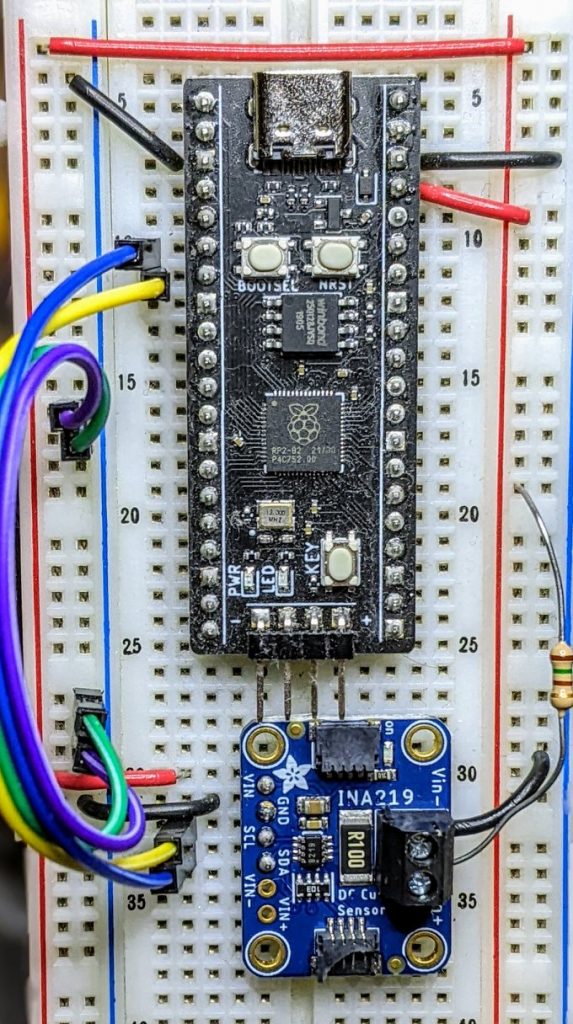
For example, take the INA219 High Side DC Current Sensor. It’s an I²C sensor able to measure up to 26 V, ±3.2 A. It does this by measuring the voltage across a 0.1 ohm precision shunt resistor with its built-in 12-bit ADC. I got a customer return from the store that was cosmetically damaged but still usable, so I thought I’d try it with the simplest module I could find in Awesome MicroPython and see how well it worked.
I guess I needed a test circuit too. Using all of what was immediately handy — a resistor I found on the bench and measured at 150.2 ohm — I came up with this barely useful circuit:
Should indicate a current of 3.3 / (150.2 + 0.1) = 21.96 mA
The INA219 would be happier with a much higher current to measure, but I didn’t have anything handy that could do that.
Looking in Awesome MicroPython’s Current section, I found robert-hh/INA219: INA219 Micropython driver. It doesn’t have much (okay, any) documentation, but it’s a very small module and the code is easy enough to follow. I put the ina219.py module file into the /lib folder of a WeAct Studio RP2040 board, and wrote the following code:
# INA219 demo - uses https://github.com/robert-hh/INA219

from machine import Pin, I2C
import ina219

i = I2C(0, scl=Pin(5), sda=Pin(4))
print("I2C Bus Scan: ", i.scan(), "\n")

sensor = ina219.INA219(i)
sensor.set_calibration_16V_400mA()

# my test circuit is 3V3 supply through 150.2 ohm resistor
r_1 = 150.2
r_s = 0.1  # shunt resistor on INA219 board

# current is returned in milliamps
print("Current       / mA: %8.3f" % (sensor.current))
# shunt_voltage is returned in volts
print("Shunt voltage / mV: %8.3f" % (sensor.shunt_voltage * 1000))
# estimate supply voltage from known resistance * sensed current
print("3V3 (sensed)  / mV: %8.3f" % ((r_1 + r_s) * sensor.current))
with everything wired up like this (Blue = SDA, Yellow = SCL):
all of the wires
Running it produced this:
I2C Bus Scan:  [64]

Current       / mA:   22.100
Shunt voltage / mV:    2.210
3V3 (sensed)  / mV: 3321.630
So it’s showing just over 22 mA: pretty close to what I calculated!
In early 2013, I must’ve been left unsupervised for too long since I made The Quite Rubbish Clock:
It still isn’t human readable …
Written in (Owen Wilson voice) kind of an obsolete vernacular and running on hardware that’s now best described as “quaint”, it was still absurdly popular at the time. Raspberry Pis were still pretty new, and people were looking for different things to do with them.
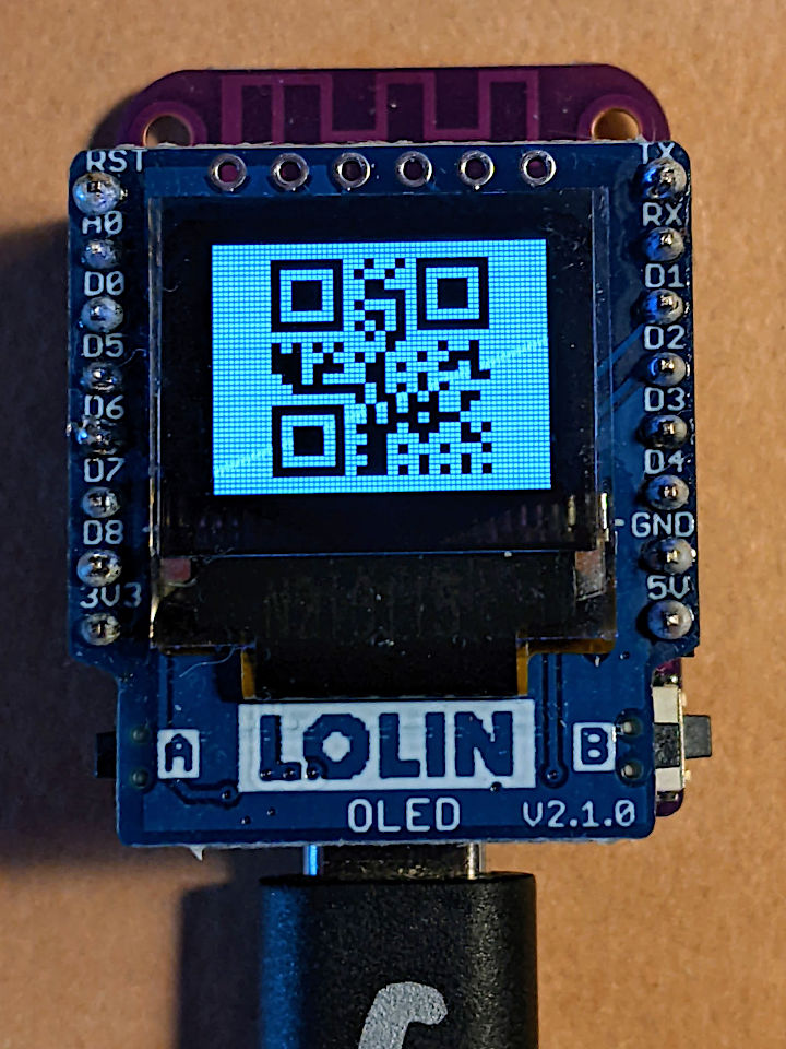
I happened across the JASchilz/uQR: QR Code Generator for MicroPython the other day, and remembered I had some tiny OLED screens that were about the same resolution as the old Nokia I’d used in 2013. I wondered: could I …?
OLED Shield on a LOLIN S2 Mini: very smol indeed
The board is a LOLIN S2 Mini with a OLED 0.66 Inch Shield on top, all running MicroPython. One limitation I found in the MicroPython QR library was that it was very picky about input formats, so it only displays the time as HHMMSS with no separators.
Source, of course:
# -*- coding: utf-8 -*-
# yes, the Quite Rubbish Clock rides again ...
# scruss, 2022-06-30
# MicroPython on Lolin S2 Mini with 64 x 48 OLED display
# uses uQR from https://github.com/JASchilz/uQR
# - which has problems detecting times with colons

from machine import Pin, I2C, RTC
import s2mini  # on Lolin ESP32-S2 Mini
import ssd1306
from uQR import QRCode

WIDTH = 64  # screen size
HEIGHT = 48
SIZE = 8  # text size
r = RTC()

# set up and clear screen
i2c = I2C(0, scl=Pin(s2mini.I2C_SCL), sda=Pin(s2mini.I2C_SDA))
oled = ssd1306.SSD1306_I2C(WIDTH, HEIGHT, i2c)
oled.fill(0)


def snazz():
    marquee = [
        "   **",
        "   **",
        "   **",
        "   **",
        "   **",
        "********",
        " ******",
        "  ****",
        "   **",
        " quite",
        "rubbish",
        " clock",
        "  mk.2",
        "<scruss>",
        " >2022<"
    ]
    for s in marquee:
        oled.scroll(0, -SIZE)  # scroll up one text line
        oled.fill_rect(0, HEIGHT-SIZE, WIDTH,
                       SIZE, 0)  # blank last line
        oled.text("%-8s" % s, 0, HEIGHT-SIZE)  # write text
        oled.show()
        time.sleep(0.25)
    time.sleep(5)
    oled.fill(1)
    oled.show()


snazz()  # tedious crowd-pleasing intro

qr = QRCode()
while True:
    qr.add_data("%02d%02d%02d" % r.datetime()[4:7])
    qr.border = 1  # default border too big to fit small screen
    m = qr.get_matrix()
    oled.fill(1)
    for y in range(len(m)):
        for x in range(len(m[0])):
            # plot a double-sized QR code, centred, inverted
            oled.fill_rect(9 + 2*x, 1 + 2*y, 2, 2, not m[y][x])
    oled.show()
    time.sleep(0.05)
    qr.clear()
If your output is glitchy, you might need to put the following in boot.py:
import machine
machine.freq(240000000)
This increases the ESP32-S2’s frequency from 160 to 240 MHz.
Update: there’s a fork of uQR that provides better character support, particularly those required for sending Wi-Fi Network config.
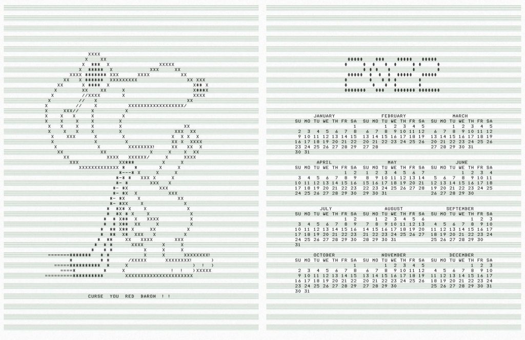
Original “WW1 Fighter Pilot” Snoopy ASCII art from “SNOOPY.BA” for the DEC PDP-8, written by Mr Kay R. Fisher of DEC some time before July 1973. It’s referred to in the first printing of the “101 Basic Computer Games” book, which was published in 1973.
ncal, banner: their respective authors
pstext an ascii to PS filter by Dan Judd, usenet comp.lang.postscript, December 1989. I had to really mess around with the output of this program to use a custom font and add the music ruling, but it produces cleaner PostScript than the giant messes that enscript and a2ps have become
Font: mnicmp, by me. Based on the DecWriter II font.
The biggest thing that tripped me up was that PicoMite BASIC starts arrays at 0. OPTION BASE 1 fixes that oversight. It would have been nice to have OpenProcessing’s HSV colour space, and an editor that could handle lines longer than 80 characters that didn’t threaten to bomb out if you hit the End key, but it’ll serve.
Source below:
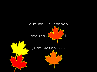
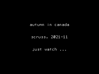
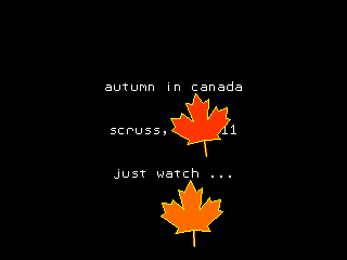
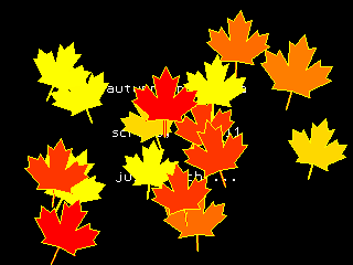
' autumn in canada
' scruss, 2021-11
' a take on my https://openprocessing.org/sketch/995420 for picomite

OPTION base 1
RANDOMIZE TIMER
' *** initialize polar coords of leaf polygon and colour array
DIM leaf_rad(24), leaf_ang(24), px%(24), py%(24)
FOR i=1 TO 24
    READ leaf_rad(i)
NEXT i
FOR i=1 TO 24
    READ x
    leaf_ang(i)=RAD(x)
NEXT i

DIM integer c%(8)
FOR i=1 TO 8
    READ r%, g%, b%
    c%(i)=RGB(r%,g%,b%)
NEXT i

' *** set up some limits
min_scale%=INT(MIN(MM.HRES, MM.VRES)/8)
max_scale%=INT(MIN(MM.HRES, MM.VRES)/6)
min_angle=-30
max_angle=30
min_x%=min_scale%
min_y%=min_x%
max_x%=MM.HRES - min_x%
max_y%=MM.VRES - min_y%

CLS
TEXT MM.HRES/2, INT(MM.VRES/3), "autumn in canada", "CM"
TEXT MM.HRES/2, INT(MM.VRES/2), "scruss, 2021-11", "CM"
TEXT MM.HRES/2, INT(2*MM.VRES/3), "just watch ...", "CM"

kt%=0
DO
    cx% = min_x% + INT(RND * (max_x% - min_x%))
    cy% = min_y% + INT(RND * (max_y% - min_y%))
    angle = min_angle + RND * (max_angle - min_angle)
    sc% = min_scale% + INT(RND * (max_scale% - min_scale%))
    col% = 1 + INT(RND * 7)
    leaf cx%, cy%, sc%, angle, c%(7), c%(col%)
    kt% = kt% + 1
LOOP UNTIL kt% >= 1024

END

SUB leaf x%, y%, scale%, angle, outline%, fill%
    FOR i=1 TO 24
        px%(i) = INT(x% + scale% * leaf_rad(i) * COS(RAD(angle)+leaf_ang(i)))
        py%(i) = INT(y% - scale% * leaf_rad(i) * SIN(RAD(angle)+leaf_ang(i)))
    NEXT i
    POLYGON 24, px%(), py%(), outline%, fill%
END SUB

' radii
DATA 0.536, 0.744, 0.608, 0.850, 0.719
DATA 0.836, 0.565, 0.589, 0.211, 0.660, 0.515
DATA 0.801, 0.515, 0.660, 0.211, 0.589, 0.565
DATA 0.836, 0.719, 0.850, 0.608, 0.744, 0.536, 1.000
' angles
DATA 270.000, 307.249, 312.110, 353.267, 356.540
DATA 16.530, 18.774, 33.215, 3.497, 60.659, 72.514
DATA 90.000, 107.486, 119.341, 176.503, 146.785, 161.226
DATA 163.470, 183.460, 186.733, 227.890, 232.751, 270.000, 270.000
' leaf colours
DATA 255,0,0, 255,36,0, 255,72,0, 255,109,0
DATA 255,145,0, 255,182,0, 255,218,0, 255,255,0
You could probably use AUTOSAVE and paste the text into the PicoMite REPL. I used an ILI9341 SPI TFT LCD Touch Panel with my Raspberry Pi Pico along with some rather messy breadboard wiring.
Fun fact: the maple leaf polygon points are derived from the official definition of the flag of Canada.


