Colour management is good. It means that what I see on the screen is what you meant it to look like, and anything I make with a colour-managed workflow you’ll see in the colours I meant it to have. (Mostly.) You can spend a lot of money to do this professionally, but you can also get most of the benefits for about $125, if you’re prepared to do some fiddly stuff.
The most important part is calibrating your display. Hughski’s ColorHug (which I’ve mentioned before) is as close to plug-and-play as you’ll get: plug it in, and the colour management software pops up with prompts on what to do next. Attach the ColorHug to the screen (with the newly supplied stretchy band), let it burble away for 10–20 minutes, and the next time you log in, colours will be just right.
Calibrating the scanner on my Epson WorkForce WF-7520 was much more work, and the process could use optimization. To calibrate any scanner, you need a physical colour target to scan and compare against reference data. The cheapest place to get these (unless there was one in the box with your scanner) is Wolf Faust’s Affordable IT 8.7 (ISO 12641) Scanner Colour Calibration Targets. If there are a bunch of likeminded folk in your area, it’s definitely worth clubbing together on a group buy to save on shipping. It’s also less work for Wolf, since he doesn’t have to send out so many little packages.
(I’ve known of Wolf Faust since my Amiga days. He produced the most glorious drivers for Canon printers, and Jeff Walker produced the camera-ready copy for JAM using Wolf’s code. While Macs had the high end DTP sewn up back then, you could do amazing things on a budget with an Amiga.)
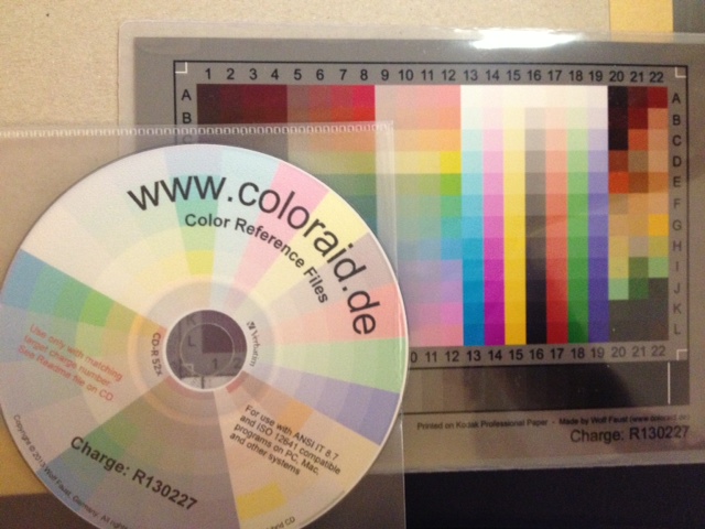 The target comes packed in a protective sleeve, and along with a CD-R containing the calibration data which matches the print run of the target. Wolf makes a lot of targets for OEMs, and cost savings from his volume clients allow him to sell to individuals cheaply.
Scanning the thing without introducing automatic image corrections was the hard part. I found that my scanner had two drivers (epson2 and epkowa), the latter of which claimed to support 48-bit scanning. Unfortunately, it only supports 24-bit, like the epson2 driver, so whichever I chose was moot. I used the scanimage command line tool to make the scan:
scanimage --mode Color -x 175 -y 125 --format=tiff --resolution 300 > Epson-Workforce_WF-7520-WFaust-R1.tiff
which looks, when reduced down to web resolution, a bit like this:
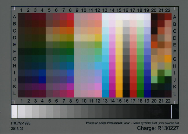 It looks a lot darker than the physical target, so it’s clear that the scanner needs calibrating. To do this, you need two tools from the Argyll Colour Management System. The first creates a text representation of the scanned target’s colour patches:
scanin -v Epson-Workforce_WF-7520-WFaust-R1.tiff /usr/share/color/argyll/ref/it8.cht IT87/r130227.txt diag.tiff
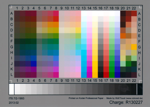
The result is a smallish text file Epson-Workforce_WF-7520-WFaust-R1.ti3 which needs one more step to make a standard ICC profile:
colprof -A Epson -M 'Workforce WF-7520' -D 'WFaust R1' -ax -qm Epson-Workforce_WF-7520-WFaust-R1
I didn’t quite need to add that much metadata, but I could, so I did. The resultant ICC file can be used to apply colour calibrations to scanned images. Here’s the target scan, corrected:
(I’ve made this a mouseover with the original image, so you can see the difference. Also, yes, there is a greasy thumb-print on my scanner glass near the bottom right, thank you so much for noticing.)
I used tifficc from the Little CMS package to apply the colour correction:
tifficc -v -i Epson-Workforce_WF-7520-WFaust-R1.icc Epson-Workforce_WF-7520-WFaust-R1.tiff Epson-Workforce_WF-7520-WFaust-R1-corrected.tiff
There are probably many easier, quicker ways of doing this, but this was the first thing I found that worked.
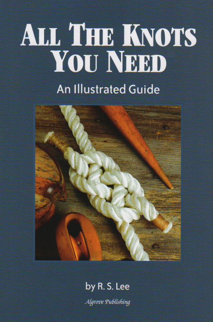
To show you a real example, here’s an un-retouched scan of the cover of Algrove Publishing‘s book “All the Knots You Needâ€, scanned at 75 dpi. Mouseover to see the corrected version:
(Incidentally, there are two old but well-linked programs that are out there that purport to do scanner calibration:Â Scarse and LPROF. Don’t use them! They’re really hard to build on modern systems, and the Argyll tools work well.)
The last part of my workflow that remains uncalibrated is my printer. I could make a target with Argyll, print it, scan it, colour correct it, then use that as the input to colprof as above. I’m suspecting the results would be mediocre, as my scanner’s bit depth isn’t great, and I’d have to do this process for every paper and print setting combination. I’d also have to work out what magic CUPS does and compensate. Maybe later, but not yet.