Here are the complete 1988-vintage Sun manuals “Using NROFF and TROFF†and “Formatting Documents†scanned just for you. I’d scanned these in 2000, and they’d sat on a forgotten archive volume since then.
It is a truth universally acknowledged, that an engineer in possession of a solid-state flammable gas detector, will shortly make a fart detector with it. I’m sorry, but call it childishness, simple-minded curiosity, or the results of a diet high in polysaccharides, but this is something I have to get out of my system. (It’s okay; I’ll waft the door.)
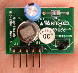
This all started when our carbon monoxide detector decided it was past its best, and started to emit an ear-splitting shriek. Thinking there might be some cool parts inside, I took it apart. Inside, in amongst the other stuff, I found this:
Thankfully, David Cook of Robot Room had once had the same idea as me (well, minus the puerile bits), and he documented the sensor board very well: Explosive Gas Detector Board. Here are the four pins that you really need to get the thing going:
Pins 2 and 3 are active low signals. To be typographically correct, I’d write them as Enable and Gas, but that’s hard to do in fixed-pitch ASCII. I can understand why the Gas signal should be active low (think about it; if the Figaro TGS 2611 sensor fails or shorts, it will likely fail to an alarm state, so you’ll still be alive to curse the bloody noise that woke you at 03h00), but the Enable being active low? Dunno.
I was hoping to have presented a little sketch for the Digispark that would have typed something unhelpful every time that gas was detected, but it was not to be. It seems that Macs and Digispark keyboard emulation is a thing of great wobbliness, so I had to resort to an Arduino and a serial connection.
Here’s the code:
/*
 gas_detector - uses board scavenged from CO detector

 scruss - 2013-02-18 (unfortunately)
 */

int gas     = 2;               // /Gas line on pin 2
int val     = 0;
int lastval = 0;

void setup() {
  pinMode(gas, INPUT);
  Serial.begin(115200);
}

void loop() {
  val = digitalRead(gas);
  if (val != lastval) {
    if (val == LOW) {          // LOW means gas detected
      Serial.println("gas");
      Serial.println();
      delay(1000);             // wait 1s for air to clear
    }
  }
  lastval = val;
}
Before you ask, I tested the circuit by briefly hitting the button on a gas lighter. Honest.
I’ll keep working on the Digispark; it’s such a nifty little device, and this is such a worthy project …
Boodler is rather fun. It generates ambient music based on user-defined or downloaded ‘soundscapes’. If you’ve got a modern (HTML5/Opus-capable) browser, you can hear a streaming demo here: http://repeater.xiph.org:8000/clock.opus. It’s using the FM3 Buddha Machine samples in this demo, but it can run lots more: a tree full of crows, a thunderstorm, dripping water, …
It’s pretty easy to run on a Raspberry Pi running a recent version of Raspbian. The only technical glitch I had was that there’s something deeply confused about ALSA sound handling on the Raspberry Pi. I’m sure it’ll get fixed soon, but for now, you have to use PulseAudio. (If you want to read about my ALSA woes, go here.)
It takes a while to do this, but make sure it does something useful when it’s building the various sound drivers. You don’t want it to say:
skipping 'boodle.cboodle_pulse' extension
If it says that, you haven’t installed Pulseaudio. Go back and check your apt-get line.
Once it’s built, now install it:
sudo python setup.py install
Now test it:
boodler --hardware --output pulse --testsound
Not merely should you get some pleasant tones from your Raspberry Pi’s audio, but you sound get some informative and non-threatening terminal output. Mine looks like:
Boodler: PulseAudio sound driver.
 PulseAudio library: 2.0.0.
 Sample rate is 44100 fps.
 Samples are 16-bit little-endian.
 Buffer size is 32768.
 21:37:46 (root) Running "Boodler test sound"
If that works, let’s get those crows a-cawin’. Download the soundscapes you need:
Boodler has tons of options, prebuilt packages, and instructions to build your own: Boodler Documentation.
One thing I’ve tried to get working, but failed, is streaming from Boodler via icecast. Sure, I can install and run it, it’s just that the results are, um, undesirable. If you want to have a play, here’s how to install icecast:
sudo apt-get install icecast2 ices2 libshout3-dev
Icecast will configure itself, and ask for a couple of passwords. You’ll have to rebuild and reinstall Boodler for it to catch the new configuration. You can then try streaming:
If you open a web browser at this address http://raspberrypi:8000/ you should see a config page listing your boodler-buddha.ogg stream. Click on the M3U link next to it, and your streaming music player should start making a joyful noise …
… except in my case, something went very wrong, and it started to produce industrial ultra-glitch nightmare noise: boodler-streaming_test-fail. I’m sure it’s fixable with some tweaking, but I’m not there yet.
Now I’ve got my X10 system running and know its limitations, I could have saved a wheen of money not buying stuff I don’t need. Our house appears to have been wired by an, um, spirited amateur, so powerline signalling is of limited use. Thankfully, the tiny and cheap X10 FireCracker CM17A (warning: too many flashing GIFs at this link!) can be driven from heyu [previously]. You can score these on eBay for under $10, and all you need is a serial adapter to drive them.
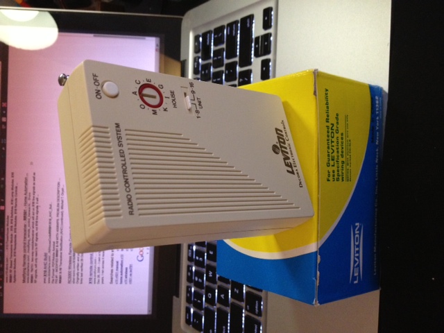
The really cheap bit in my system was discovered in Active Surplus. I found a case of Leviton “Plug-in Frequency Transceiver Modules” for $4/each. One was out of its case, and wouldn’t you know it, it’s the same as a RR501 module, which typically retails for about $30. Sure, these are old stock and are a nasty beige colour, but they provide a way of switching a two-pin appliance. They can also relay remote commands from RF to wired controls.
The only X10 controller I can’t get to work with the Raspberry Pi is the CM19a USB PC Transceiver. I suspect it draws a bit too much power to run from a Raspberry Pi, as it makes the machine unresponsive if it’s plugged it. Running from my bench setup it works fine with the mochad driver, but no dice with the other machine. The CM19a reads wireless RF X10 commands, and it would be useful if I’d added a motion sensor. As is, I’ll stick to the lights going on and off.
(Update: there’s a good chance that my CM19a problems are down to the ancient dwc_otg* fixes I still run on my Raspberry Pi’s kernel. You probably don’t need them, and this device could work fine. One day I will find time to fix ’em …)
(Incidentally, this is the “North American Edition” because X10 RF controls are completely different in Europe, and none of the above is useful to you. Yeah, I know this article is the equivalent of PC Load Letter to you; sorry.)
Hey! This is a really old article. You should really be using gpiozero these days.
I hadn’t realised it, but the The Quite Rubbish Clock did something that a lot of people seem to have trouble with on the Raspberry Pi: communicating using hardware SPI. Perhaps it’s because everything is moving so fast with Raspberry Pi development, tutorials go out of date really quickly. Thankfully, hardware SPI is much easier to understand than the older way of emulation through bit-banging.
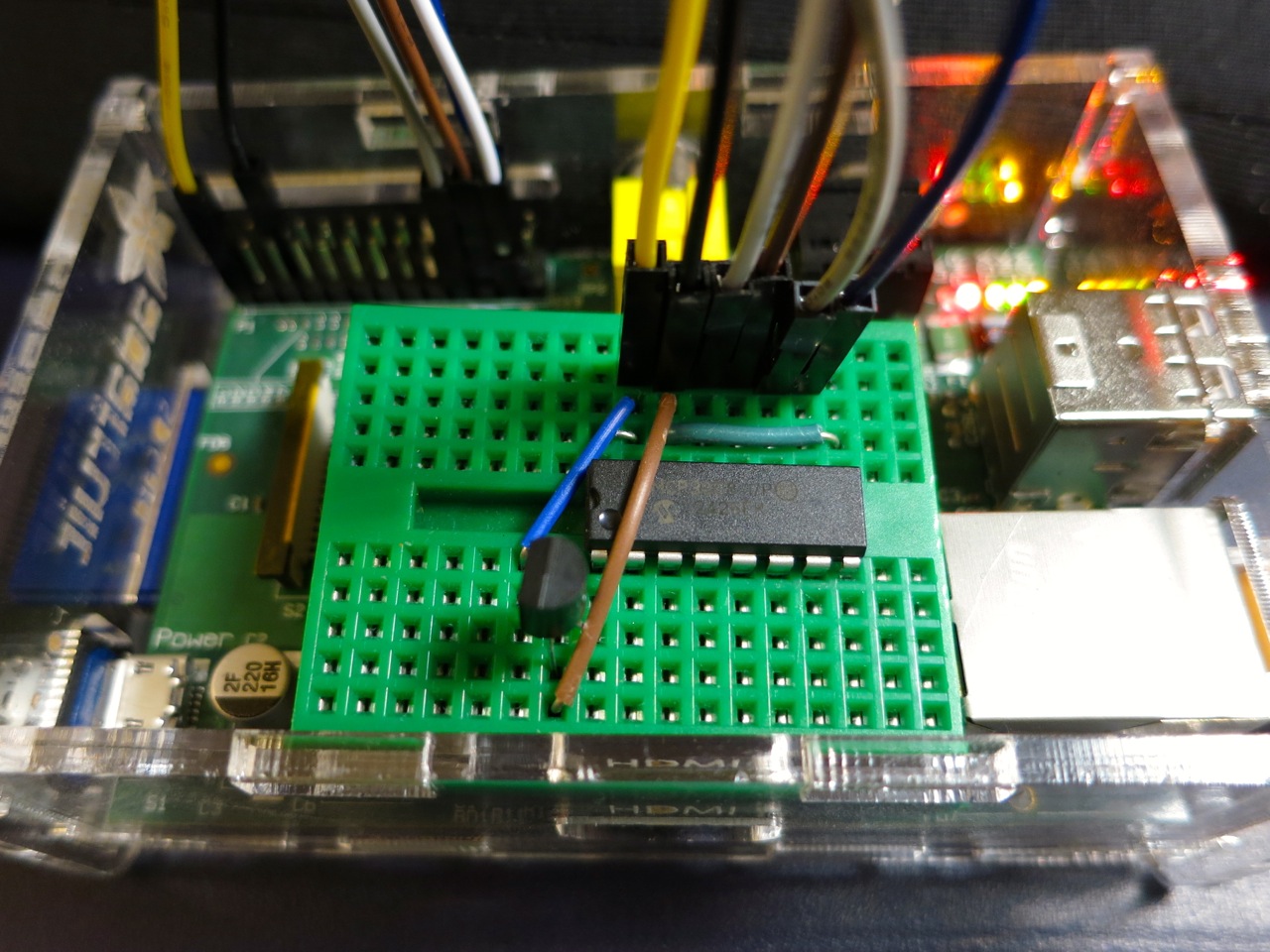
SPI is a synchronous serial protocol, so it needs a clock line as well as a data in and data out line. In addition, it has a Chip Enable (CE, or Chip Select, CS) line that is used to choose which SPI device to talk to. The Raspberry Pi has two CE lines (pins 24 and 26) so can talk to two SPI devices at once. It supports a maximum clock rate of 32 MHz, though in practice you’ll be limited to the rate your device supports.
The device I’m testing here is an MCP3008 10-bit Analogue-to-Digital Converter (ADC). These are simple to use, cheap and quite fast converters with 8 input channels. If you hook them up to a 3.3 V supply they will convert a DC voltage varying from 0-3.3 V to a digital reading of 0-1023 (= 210 – 1). Not quite up there in quality for hi-fi audio or precision sensing, but good enough to read from most simple analogue sensors.
The sensor I’m reading is the astonishingly dull LM35DZ temperature sensor. All the cool kids seem to be using TMP36s (as they can read temperatures below freezing without a negative supply voltage). One day I’ll show them all and use a LM135 direct Kelvin sensor, but not yet.
The code I’m using is a straight lift of Jeremy Blythe’s Raspberry Pi hardware SPI analog inputs using the MCP3008. The clever bit in Jeremy’s code is the readadc() function which reads the relevant length of bits (by writing the same number of bits; SPI’s weird that way) from the SPI bus and converting it to a single 10-bit value.
#!/usr/bin/python
# -*- coding: utf-8 -*-
# mcp3008_lm35.py - read an LM35 on CH0 of an MCP3008 on a Raspberry Pi
# mostly nicked from
#  http://jeremyblythe.blogspot.ca/2012/09/raspberry-pi-hardware-spi-analog-inputs.html

import spidev
import time

spi = spidev.SpiDev()
spi.open(0, 0)

def readadc(adcnum):
# read SPI data from MCP3008 chip, 8 possible adc's (0 thru 7)
    if adcnum > 7 or adcnum < 0:
        return -1
    r = spi.xfer2([1, 8 + adcnum << 4, 0])
    adcout = ((r[1] & 3) << 8) + r[2]
    return adcout

while True:
    value = readadc(0)
    volts = (value * 3.3) / 1024
    temperature = volts / (10.0 / 1000)
    print ("%4d/1023 => %5.3f V => %4.1f °C" % (value, volts,
            temperature))
    time.sleep(0.5)
The slightly awkward code temperature = volts / (10.0 / 1000) is just a simpler way of acknowledging that the LM35DZ puts out 10 mV (= 10/1000, or 0.01) per °C. Well-behaved sensors generally have a linear relationship between what they indicate and what they measure.
If you run the code:
sudo ./mcp3008_lm35.py
you should get something like:
  91/1023 => 0.293 V => 29.3 °C
  93/1023 => 0.300 V => 30.0 °C
  94/1023 => 0.303 V => 30.3 °C
  95/1023 => 0.306 V => 30.6 °C
  96/1023 => 0.309 V => 30.9 °C
  97/1023 => 0.313 V => 31.3 °C
  97/1023 => 0.313 V => 31.3 °C
  98/1023 => 0.316 V => 31.6 °C
  99/1023 => 0.319 V => 31.9 °C
  99/1023 => 0.319 V => 31.9 °C
 100/1023 => 0.322 V => 32.2 °C
 100/1023 => 0.322 V => 32.2 °C
 100/1023 => 0.322 V => 32.2 °C
 101/1023 => 0.325 V => 32.5 °C
 101/1023 => 0.325 V => 32.5 °C
 102/1023 => 0.329 V => 32.9 °C
 102/1023 => 0.329 V => 32.9 °C
 103/1023 => 0.332 V => 33.2 °C
Note that the sensor had been sitting over the Raspberry Pi’s CPU for a while; I don’t keep my house at 29 °C. I made the temperature go up by holding the LM35.
So, you’ve just (fairly cheaply) given your Raspberry Pi 8 analogue input channels, so it can behave much more like a real microcontroller now. I remember from my datalogging days that analogue inputs can be pretty finicky and almost always return a value even if it’s an incorrect one. Check the chip’s datasheet to see if you’re doing it right, and if in doubt, meter it!
The video of the Quite Rubbish Clock isn’t running the same code that’s in the listing. Here it is, showing off some of the handy code that’s in bgreat’s nokiaSPI Python class:
#!/usr/bin/python
# -*- coding: utf-8 -*-
# qrmovie
import time
# need to use git://github.com/mozillazg/python-qrcode.git
import qrcode
from PIL import Image, ImageFont
import ImageOps
# uses bgreat's SPI code; see
# raspberrypi.org/phpBB3/viewtopic.php?f=32&t=9814&p=262274&hilit=nokia#p261925
import nokiaSPI
noki = nokiaSPI.NokiaSPI()Â Â Â Â Â Â Â Â Â Â Â Â Â # create display device
qr = qrcode.QRCode(version=1,          # V.1 QR Code: 21x21 px
error_correction=qrcode.constants.ERROR_CORRECT_M,
box_size=2, border=1)
bg = Image.new('1', (84, 48))Â Â Â Â Â Â Â Â Â Â # blank (black) image background
# intro
noki.cls()
noki.led(0)
time.sleep(3)
for i in range(0,769,32):
noki.led(i)
time.sleep(0.04)
# display is 14 columns by 8 rows
noki.centre_word(1, 'scruss.com')
noki.centre_word(3, 'presents')
time.sleep(3)
noki.cls()
noki.centre_word(1, 'qrclock')
noki.centre_word(2, 'the')
noki.gotorc(3,3)
noki.text("[Q]uite")
noki.gotorc(4,3)
noki.text("[R]ubbish")
noki.gotorc(5,3)
noki.text(" Clock")
time.sleep(3)
elapsed=0
start_time = time.time()
while (elapsed<12):
qr.clear()
newbg = bg.copy()Â Â Â Â Â Â Â Â Â Â Â Â Â Â Â Â Â Â # copy blank background
s = time.strftime('%Y-%m-%d %H:%M:%S')
qr.add_data(s)Â Â Â Â Â Â Â Â Â Â Â Â Â Â Â Â Â Â Â Â Â # make QR Code of YYYY-MM-DD HH:MM:SS
qr.make()
qrim = qr.make_image()Â Â Â Â Â Â Â Â Â Â Â Â Â # convert qrcode object to PIL image
qrim = qrim.convert('L')Â Â Â Â Â Â Â Â Â Â Â # make greyscale
qrim = ImageOps.invert(qrim)Â Â Â Â Â Â Â # invert colours: B->W and W->B
qrim = qrim.convert('1')Â Â Â Â Â Â Â Â Â Â Â # convert back to 1-bit
newbg.paste(qrim, (18, 0))Â Â Â Â Â Â Â Â Â # paste QR Code into blank background
noki.show_image(newbg)Â Â Â Â Â Â Â Â Â Â Â Â Â # display code on LCD
time.sleep(0.4)Â Â Â Â Â Â Â Â Â Â Â Â Â Â Â Â Â Â Â Â # pause before next display
elapsed = time.time() - start_time
noki.cls()
noki.centre_word(1, 'for')
noki.centre_word(2, 'more')
noki.centre_word(3, 'details')
time.sleep(3)
noki.cls()
noki.load_bitmap("blogpost-nokia.bmp", True)
time.sleep(7)
noki.cls()
noki.centre_word(3, 'fin')
noki.centre_word(5, 'scruss, 2013')
time.sleep(1)
for i in range(768,-1,-32):
noki.led(i)
time.sleep(0.05)
time.sleep(1)
noki.cls()
Lines 43-58 show off the QR clock for a maximum of 12 seconds. Any more, and you’d get really bored.
The screen handling functions I used are:
cls() — Clears the screen.
led(brightness) — sets the backlight to brightness. For me, full brightness is at 768. A value of zero turns the backlight off. If you don’t have the screen LED connected to one of the Raspberry Pi’s PWM pin, this will either be full on (for any brightness >= 1), or off, for brightness=0. This is used to fade up the screen in lines 24-26, and fade it down far too theatrically in lines 72-74.
show_image(PILImage) — display a single bit depth black and white Python Imaging Library object PILImage. This can be no larger than 84×48 pixels.
load_bitmap(file, Invert) — load a single bit depth black and white BMP file of maximum size 48×84. If Invert is true, keep the colours as they are, otherwise swap black and white to make a negative image. nokiSPI flips images by 90°, so the image I loaded to show the URL of the blog post looks like this:
(I know, I could have generated this in code, but I’d already made the image using qrencode. I couldn’t be bothered working out the image size and offsets.)
The text handling functions I used are:
gotorc(row, column) — move the text cursor to row, column. The screen only has 14 columns by 8 rows if you use the standard 6×6 pixel font, so keep your text short to avoid disappointment.
text(text) — write text at the current cursor position.
centre_word(row, text) — write text centred in row row. Since the text rows are a maximum of 14 columns, text with an odd number of characters will appear slightly off-centre.
There are many more functions in the nokiaSPI class; watch the demo, have a dig through the source and see what you can use.
Update: Eep! This post was featured on the Raspberry Pi blog today. Thanks, Liz!
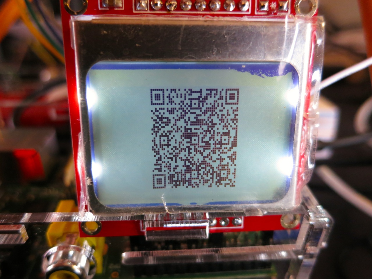
And now for something completely different:
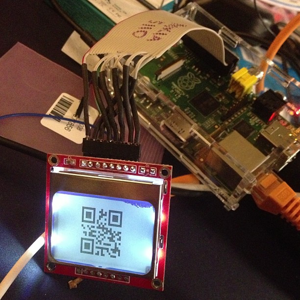
… a clock that isn’t human readable. You’ll need a QR code reader to be able to tell the time.
This, however, is not the prime purpose of the exercise. I was looking for an excuse to try some direct hardware projects with the GPIO, and I remembered I had a couple of Nokia-style surplus LCDs lying about that could be pressed into service. These LCDs aren’t great: 84×48 pixels, 3V3 logic, driven by SPI via an 8-pin header which includes PWM-controllable LED backlighting. They are cheap, and available almost everywhere: DealExtreme ($5.36), SparkFun ($9.95), Adafruit ($10, but includes a level shifter, which you really need if you’re using a 5V logic Arduino), Solarbotics ($10) and Creatron (about $12; but you can walk right in and buy one). Despite being quite difficult to use, helpful people have written drivers to make these behave like tiny dot-addressable screens.
I’d been following the discussion on the Raspberry Pi forum about driving the Nokia LCD from a Raspberry Pi. Only when user bgreat posted some compact code that was supposed to run really fast did I dig out the LCD board and jumper wires. Building on bgreat’s nokiaSPI.py class and a few other bits of code, here’s what I built to make this singularly pointless clock:
#!/usr/bin/python
# -*- coding: utf-8 -*-
# qrclock - The Quite Rubbish Clock for Raspberry Pi - scruss, 2013-01-19
import time
# need to use git://github.com/mozillazg/python-qrcode.git
import qrcode
from PIL import Image
import ImageOps
# uses bgreat's SPI code; see
# raspberrypi.org/phpBB3/viewtopic.php?f=32&amp;amp;amp;t=9814&amp;amp;amp;p=262274&amp;amp;amp;hilit=nokia#p261925
import nokiaSPI
noki = nokiaSPI.NokiaSPI() # create display device
qr = qrcode.QRCode(version=1, # V.1 QR Code: 21x21 px
error_correction=qrcode.constants.ERROR_CORRECT_M,
box_size=2, border=1)
bg = Image.new('1', (84, 48)) # blank (black) image background
while 1:
qr.clear()
newbg = bg.copy() # copy blank background
s = time.strftime('%Y-%m-%d %H:%M:%S')
qr.add_data(s) # make QR Code of YYYY-MM-DD HH:MM:SS
qr.make()
qrim = qr.make_image() # convert qrcode object to PIL image
qrim = qrim.convert('L') # make greyscale
qrim = ImageOps.invert(qrim) # invert colours: B-&amp;amp;gt;W and W-&amp;amp;gt;B
qrim = qrim.convert('1') # convert back to 1-bit
newbg.paste(qrim, (18, 0)) # paste QR Code into blank background
noki.show_image(newbg) # display code on LCD
time.sleep(0.4) # pause before next display
(Convenient archive of all the source: qrclock2.zip, really including bgreat’s nokiaSPI class this time …)
To get all this working on your Raspberry Pi, there’s a fair amount of configuration. The best references are bgreat’s own comments in the thread, but I’ve tried to include everything here.
Enabling the SPI kernel module
As root, edit the kernel module blacklist file:
sudo vi /etc/modprobe.d/raspi-blacklist.conf
Comment out the spi-bcm2708 line so it looks like this:
#blacklist spi-bcm2708
Save the file so that the module will load on future reboots. To enable the module now, enter:
sudo modprobe spi-bcm2708
Now, if you run the lsmod command, you should see something like:
Module                  Size  Used by
spi_bcm2708             4421  0
Installing the WiringPi, SPI and other required packages
WiringPi by Gordon is one of the neater Raspberry Pi-specific modules, as it allows relatively easy access to the Raspberry Pi’s GPIO pins. For Raspbian, there are a few other imaging libraries and package management tools you’ll need to install here:
Finding a library that provided all the right functions was the hardest part here. I ended up using mozillazg‘s fork of lincolnloop‘s python-qrcode module. mozillazg’s fork lets you use most of the lovely PIL methods, while the original hides most of them. Since I had to do some image compositing and colour remapping to make the image appear correct on the Nokia screen, the new fork was very helpful.
To install it:
git clone git://github.com/mozillazg/python-qrcode.git
cd python-qrcode/
sudo python ./setup.py install
The tiny 84×48 resolution of the Nokia screen doesn’t give you many options for sizing QR codes. For the time display of the clock, a 21×21 module Version 1 code with two pixels per module and one module margin just fits into 48 pixels. Using a medium level of error correction, you can fit the 19-character message (such as “2013-01-19 18:56:59”) into this tiny screen with a very good chance of it being read by any QR code reader.
(In the video, there’s a much larger QR code that’s a link to this blog post. That’s a Version 7 code [45×45 modules] at one pixel per module and no margin. This doesn’t meet Denso Wave’s readability guidelines, but the Nokia screen has large blank margins which seem to help. It won’t read on every phone, but you’re here at this link now, so you don’t need it …)
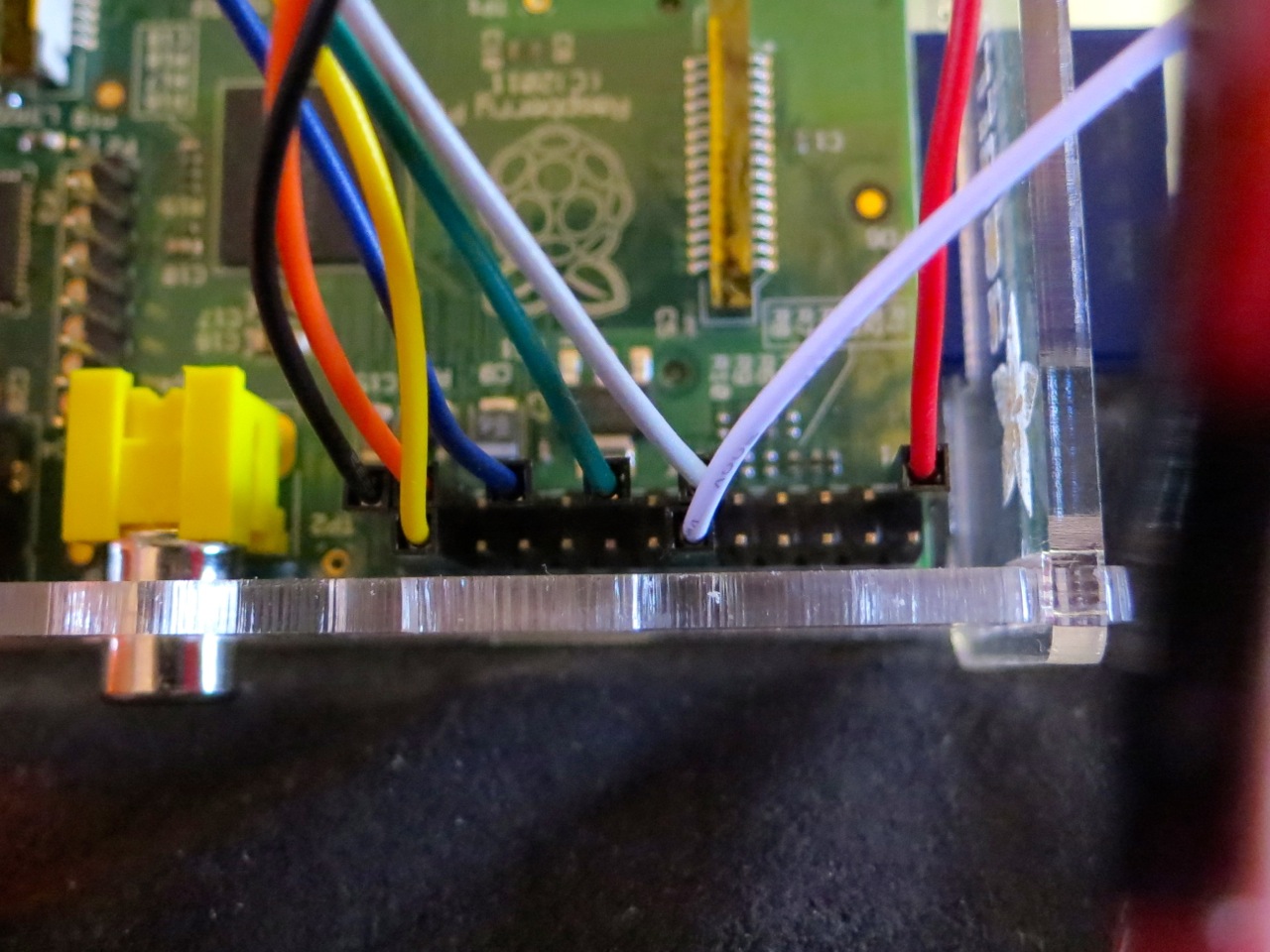
Wiring it all up
(Do I really need to say that you’ll be messing around with the inner delicate bits of your Raspberry Pi here, and if you do something wrong, you could end up with a dead Raspberry Pi? No? Okay. Just make sure you take some static precautions and you really should have the thing shut down and powered off.)
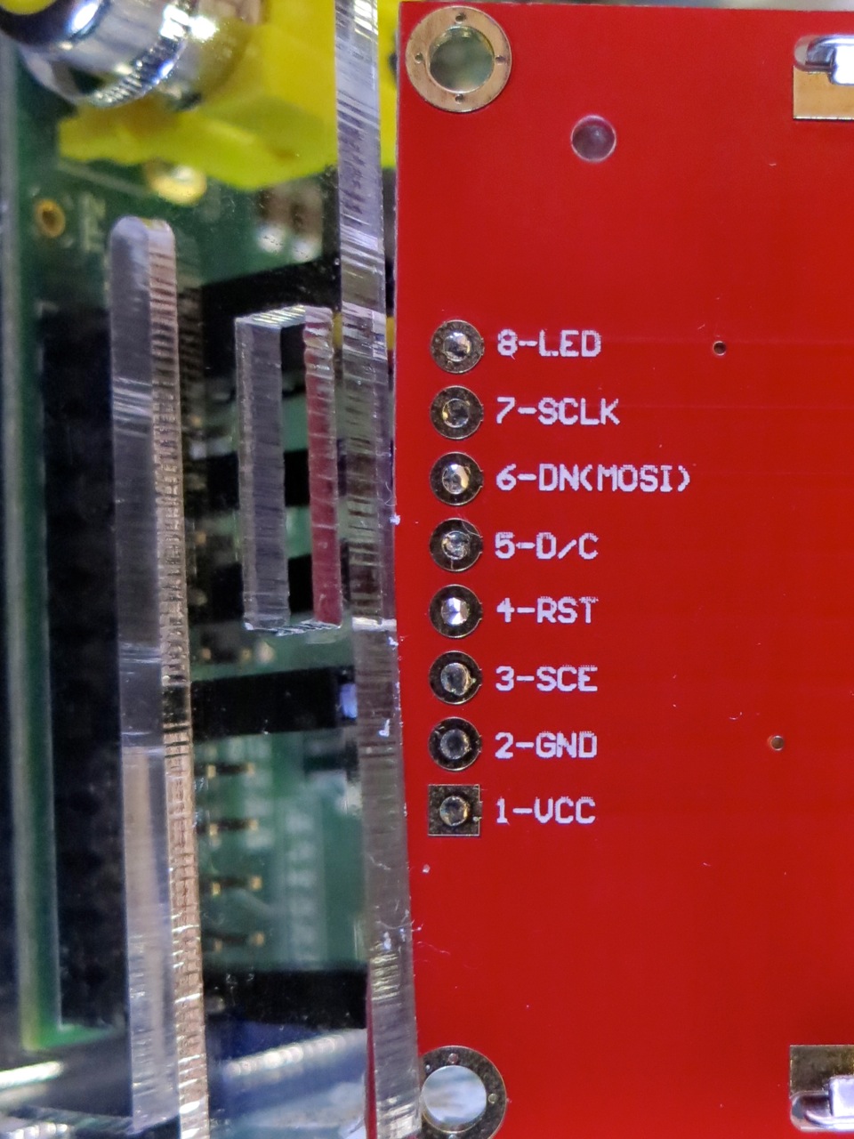
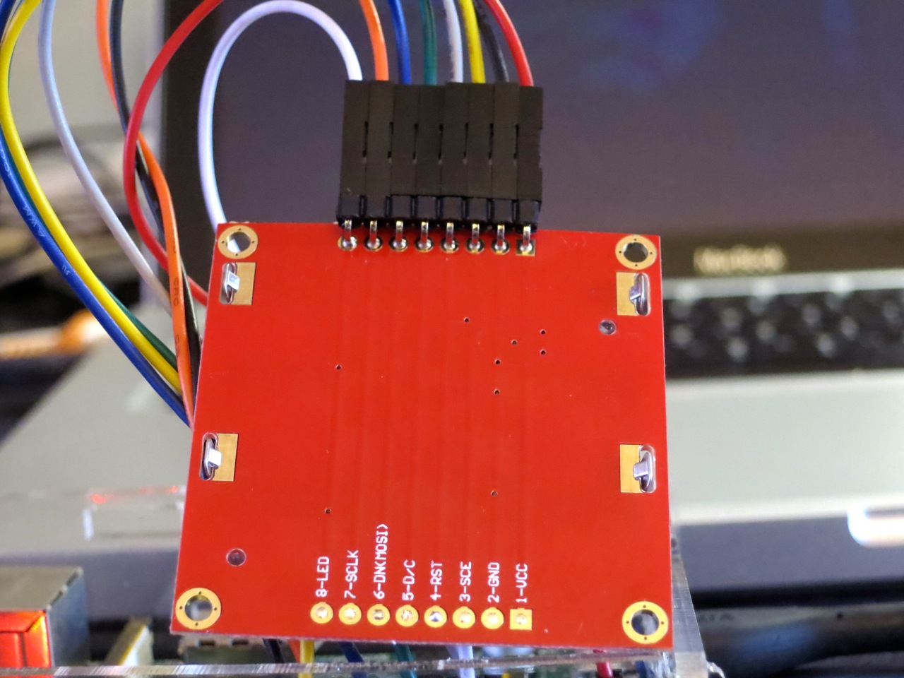
You’ll need 8 female-female right-angled ones). Note that the thick border of the LCD is the top of the screen. These boards are made who-knows-where by who-knows-whom, and there’s a hugevariety of labels and layouts on the pins. My one appears to be yet another variant, and is labelled:
VCC
GND
SCE
RST
D/C
DNK(MOSI)
SCLK
LED
This is how I wired it (from comments in bgreat’s code and the GPIO reference):
 LCD Pin       Function      Pi GPIO Pin #   Pi Pin Name
============= ============= =============== =============
 1 VCC         Vcc            1              3.3 V
 2 GND         Ground        25              GND
 3 SCE         Chip Enable   24              GPIO08 SPI0_CE0_N
 4 RST         Reset         11              GPIO17
 5 D/C         Data/Command  15              GPIO22
 6 DNK(MOSI)   Data In       19              GPIO10 SPI0_MOSI
 7 SCLK        Serial Clock  23              GPIO11 SPI0_SCLK
 8 LED         Backlight     12              GPIO18 PWM0
Wire it up, and fire up the program:
sudo ./qrclock.py
Yes, code that accesses GPIO needs to be run as root. Pesky, but helps you avoid running code that accidentally scrams the nuclear power station you’re controlling from your Raspberry Pi …
I have, of late, been rather more attached to QR Codes than might be healthy. I’ve been trying all sorts of sizes and input data, printing them, and seeing what camera phones can scan them. I tried three different devices to scan the codes:
iPhone 4s – 8 MP, running either i-nigma (free) or Denso Wave’s own QRdeCODE ($2). QRdeCODE is better, but then, it should be, since it was created by the developer of the QR Code standard.
Nexus 7 – 1.2 MP, running Google Goggles.
Nokia X2-01 – Catherine‘s new(ish) phone, which I can’t believe only has a 0.3 MP VGA camera on it. Still, it worked for a small range of codes.
QR Code readability is defined by the module size; that is, the number of device pixels (screen or print) that represent a single QR Code pixel. Denso Wave recommends that each module is made up of 4 or more dots. I was amazed that the iPhone could read images with a module size of 1 from the screen, like this one:
On this laptop, one pixel is about 0.24 mm. The other cameras didn’t fare so well on reading from the screen:
iPhone 4s – Min module size: 1-2 pixels (0.24-0.48 mm/module)
Nexus 7 – Min module size: 2-3 pixels (0.48-0.72 mm/module)
Nokia X2-01 – Min module size: 3-4 pixels (0.72-0.96 mm/module)
So I guess for screen scanning, Denso Wave’s recommendation of 4 pixels/module will pretty much work everywhere.
I then generated and printed a bunch of codes on a laser printer, and scanned them. The results were surprisingly similar:
iPhone 4s – Min module size: 3-4 dots (0.25-0.34 mm/module)
Nexus 7 – Min module size: 4-5 dots (0.34-0.42 mm/module)
Nokia X2-01 – Min module size: 8-9 dots (0.68-0.76 mm/module)
A test print on an inkjet resulted in far less impressive results. I reckon you need to make the module size around 25% bigger on an inkjet than a laser, perhaps because the inkjet is less crisp.
I have to admit I went a bit nuts with QR Codes. I made a Vcard:
(and while I was at it, I created a new field for ham radio operators: X-CALLSIGN. Why not?). I even encoded some locations in QR Codes.
Just to show you what qrencode can do, here’s a favourite piece of little prose:
Hey! This article is really old. The advice given here will not work on a Raspberry Pi 3, and will need some care with recent versions of Raspbian.
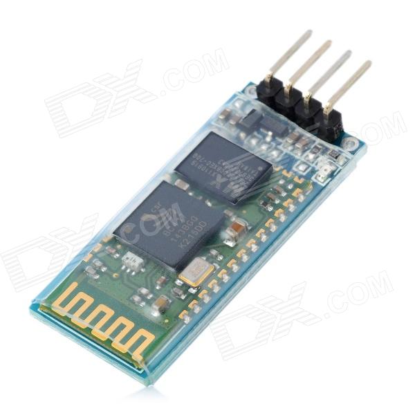
Sometimes you find a computer component that’s so cheap, that works so well, that you’re amazed you managed to live without it for so long. The JY-MCU Arduino Bluetooth Wireless Serial Port Module is that component for me right now.
JY-MCU Arduino Bluetooth Wireless Serial Port Module from dx.com
This little board is a cheap ($8.50!) Bluetooth serial port. It’s happy with the Raspberry Pi’s 3.3 V logic levels, and will communicate at standard rates between 1200 and 1,382,400 baud. It even comes with a nifty little cable which is just the right polarity for the Raspberry Pi’s GPIO pins. It’s really meant to do serial comms on an Arduino, but it’s not limited to that.
What this board allows you to do is connect to your Raspberry Pi’s serial console via Bluetooth. That way, you can have your Raspberry Pi hidden away somewhere, and yet still log in as if you were talking to it directly through a serial cable. Combine this with a USB wireless adaptor (like the Belkin N150 that I use) and you’ve got a wireless device you can always connect to, even if your network goes down.
In order to use this device with your Raspberry Pi, you’re going to have to do some reconfiguration. Exactly what reconfiguration you do depends on some additional hardware:
If you have a USB-TTL Serial converter (like an FTDI Friend, FTDI Basic Breakout – 3.3V, or the one I use, the OSEPP FTDI), you can reconfigure the Bluetooth module to run at 115,200 baud, the default speed of the Raspberry Pi’s serial port.
If you don’t have the serial converter, you’ll need to reconfigure the Raspberry Pi’s serial terminal to run at the JY-MCU Bluetooth adapter’s default 9600 baud.
To reconfigure the Bluetooth module to run at 115,200 baud
(I chose this option, as it allows me to use the Bluetooth module with Firmata on an Arduino, too.)
The JY-MCU board comes with no instructions, but all the reconfiguration commands you’ll need are explained here: hc06_linvor_1.5_at_command_set[[hc06_linvor_1.5_at_command_set]] (cached copy; original has gone) While you’re setting the communications speed, you’ll probably also want to change the device name (so you can more easily recognize your own board, as the default is something like “Linvor”) and PIN (for that warm feeling of security that only a four digit code can provide). The device is configured using AT commands (or as we eldsters call them, Hayes commands) by plugging it directly into a USB-TTL Serial device attached to your computer. Here’s how you wire it:
USB-TTL Serial    Bluetooth Serial
================= =================
GND               GND
VCC               VCC
TXD               RXD
RXD               TXD
Note that TXD and RXD are crossed. The Bluetooth unit runs on a 3.6-6V supply, but 3.3V logic. To enter the AT commands, start a serial terminal (Hyperterm, minicom, screen …) at 9600 baud talking to the USB-Serial adapter, and copy and paste these commands in:
AT+NAMEBluey
AT+PIN4321
AT+BAUD8
You’ll have to disconnect the terminal and reconnect at 115,200 baud, as that last command just reset the Bluetooth device’s speed. You might want to use other settings than Bluey for the name and 4321 for the PIN, too.
Update: check that your Raspberry Pi’s /boot/cmdline.txt contains:
console=ttyAMA0,115200
You will not get a login prompt otherwise.
Now go to Using the Device.
To reconfigure the Raspberry Pi’s serial terminal to run at 9600 baud
Serial terminals traditionally ran at 9600 baud, and that seems a bit slow these days. But, if you don’t have a way of setting up the Bluetooth device differently, 9600 is what you’re stuck with. You’ll need to edit your Raspberry Pi’s /boot/cmdline.txt so that the part that previously read:
console=ttyAMA0,115200 kgdboc=ttyAMA0,115200
to
console=ttyAMA0,9600 kgdboc=ttyAMA0,9600
Note that this file should only contain one line, so be careful you don’t add extra line breaks or your Raspberry Pi won’t boot. Save the file, reboot your Raspberry Pi, and go to the next section.
Using the Device
On your Raspberry Pi, connect the Bluetooth Wireless Serial Port Module as follows:
Raspberry Pi      Bluetooth Serial
================= =================
5V  (GPIO Pin  2) VCC
GND (GPIO Pin  6) GND
TXD (GPIO Pin  8) RXD
RXD (GPIO Pin 10) TXD
(Despite the minimum 3.6V rating, I’m happily running mine from the 3V3 power, GPIO Pin 1. YMMV.)
When the board gets power, but isn’t paired, the LEDs on the Bluetooth module flash quickly. Now you need to pair the device with your computer (use 0000 as the PIN, or whatever you chose if you changed it), and it will appear as a serial port on your machine. On my Mac, that’s a device called /dev/tty.Bluey-DevB. The LEDs stop flashing when the port goes into use. Open up a serial terminal, set the device and speed correctly, and if all goes well, you should see:
I never quite get the hang of setting timers for lights. Either I forget daylight savings completely, or I set something so general that I find the lights coming on mid-afternoon when it’s still light. Minor annoyances require the over-application of technology, and fast!
I scored an X10 ActiveHome Starter Kit for cheap(ish) on eBay. X10 is a pretty old technology (1970s! Scottish!) and has some severe limitations (slow! prone to interference! unencrypted!) but has a large user base, and did I mention it’s pretty cheap?
The key component of a computer controlled X10 system is the CM11 computer interface. It takes serial commands from a computer, and pushes them out (slowly) as signals modulated over your house wiring. Various plug-in modules pick up these signals, and if the device address in the command matches that of the module, the module turns on (or off, or dims).
Since the version of the CM11 interface that I have is serial, I’ll need a USB→Serial converter. All I had lying around was a very old Prolific PL2303 interface, which works fine with Raspbian, but I’d prefer an FTDI one for more reliability. Long-term stability of USB Serial on the Raspberry Pi is currently questionable; there’s some good discussion on kernel parameters that might help.
To send X10 commands from a Raspberry Pi (or indeed, any Linux computer) you need heyu. You have to build it from source, but the instructions are clear, and it takes about 10 minutes to build on a 256 MB Raspberry Pi. The install script asks you where your serial port is, and for my device it is /dev/ttyUSB0.
(Update: I re-imaged the Raspberry Pi that runs these tasks today and rebuilt heyu without success. Don’t assume you can do a ./configure; make; sudo make install here. You have to run heyu’s own ./Configure.sh first before make. It does some non-obvious magic. Read the README and you’ll be fine, unlike me …)
Most of the lights in our house are fluorescent, which is a problem for the standard X10 lamp modules. CFLs are not dimmable, and the standard lamp module doesn’t work with them. The lamp modules don’t work very well with low-voltage halogen lamps, either; extreme buzzing ensues, with a faint brownish light oozing out from the bulb and a vague burning smell. Best avoided, and better to use an appliance module, which is a simple mechanical relay.
The only controller that came with the kit that would work with my lights was the X10 transceiver, which also includes an appliance switch. I gave this device an address of H9 (house code H, unit code 9), and plugged in a lamp. To turn it on, I issued this command:
heyu on H9
After about 8-10 a couple of seconds and a loud CLUNK from the controller’s relay, the light came on (if it’s taking longer, read this comment). To turn it off, I told it:
heyu off H9
Whoa! Raw power! I can now turn AC devices on and off from my Raspberry Pi (Martin Creed, watch out!). I guess I could set up cron jobs to control the lights, but cron doesn’t know about solar time (Sunwait and SunCron do, if you want to futz with them). I’ve got MisterHouse running on the Raspberry Pi for more clever control, but more on setting that up later.
Incidentally, if you’re in Europe, Marmitek sell a variety of 220 V 50 Hz X10 modules. Their website is much clearer than the angry-fruit-salad that is x10.com. It looks like X10 have updated their starter kit to include the newer CM15 USB interface which will likely not work with heyu.
You have to be of a certain age to recognize this:
… not just as an artist’s travel palette, but as a repurposed case for a 9-track tape spool. While tape drives were iconic for mainframe computers (so much so, there’s a Unicode glyph for them: ✇), the last drives and tapes came off the line a decade ago. They’re not truly dead until everybody forgets what these cases were originally for.
The Raspberry Pi’s hardware and software support has come a long way in the few months it has been in the wild. I first tried this application in the summer, and the results were dismal. Now, thanks much improved USB driver support under Raspbian, I’m pleased to say it works flawlessly.
Earlier this year, I bought a turntable (ack!) for transferring vinyl to mp3. I have a TC-772 USB phono preamp, which spits out a 48 kHz stereo audio stream. If you plug the USB output of the preamp into a Rapberry Pi (running Raspbian Wheezy with all the updates), it’s instantly recognized as an audio device:
$ lsusb
Bus 001 Device 001: ID 1d6b:0002 Linux Foundation 2.0 root hub
Bus 001 Device 002: ID 0424:9512 Standard Microsystems Corp.
Bus 001 Device 003: ID 0424:ec00 Standard Microsystems Corp.
Bus 001 Device 004: ID 08bb:2902 Texas Instruments Japan PCM2902 Audio Codec
If you install the ALSA recording utilities (sudo apt-get install alsa-utils pulseaudio – this should pull in a whole bunch of necessary packages), you can record directly from this device with the following command:
which records from the ‘pulse’ audio device, displaying a stereo text VU meter (handy for setting levels), writing to a two channel 16-bit 48 kHz file called ‘out.wav’ for a maximum of 900 seconds (15 minutes). arecord has a baffling number of recording source options; arecord -L will show them. ‘pulse’ was the first one I tried.
So how does it sound? Here’s a 30 second excerpt from the only single I owned for years, The Music Tapes‘ “The Television Tells Us/Freeing Song by Reindeer”: Freeing Song by Reindeer – excerpt [mp3]. I’ve saved an even smaller snippet as lossless FLAC so you can see that the waveform’s pretty clean: FreeingSongbyReindeer-tiny_excerpt [flac].
— an Arduino driving a stepper motor driving a Sankyo musical box. And yes, heat-shrink tubing ‘reinforced’ with dental floss doesn’t make a very robust flexible coupling.
Whoa! This is so old I don’t even know where to start!
It’s using Python 2, so if it works at all it probably won’t for much longer, and Tkinter is something completely different under Python 3
(grrreat planning there, Python guys …)
pyfirmata is likely ancient history too.
Phil sent me a note last week asking how to turn an LED on or off using Python talking through Firmata to an Arduino. This was harder than it looked.
It turns out the hard part is getting the value from the Tkinter Checkbutton itself. It seems that some widgets don’t return values directly, so you must read the widget’s value with a get() method. This appears to work:
#!/usr/bin/python
# turn an LED on/off with a Tk Checkbutton - scruss 2012/11/13
# Connection:
# - small LED connected from D3, through a resistor, to GND
import pyfirmata
from Tkinter import *
# Create a new board, specifying serial port
# board = pyfirmata.Arduino('/dev/ttyACM0') # Raspberry Pi
board = pyfirmata.Arduino('/dev/tty.usbmodem411') # Mac
root = Tk()
var = BooleanVar()
# set up pins
pin3 = board.get_pin('d:3:o') # D3 On/Off Output (LED)
def set_led(): # set LED on/off
ledval = var.get()
print "Toggled", ledval
pin3.write(ledval)
# now set up GUI
b = Checkbutton(root, text = "LED", command = set_led,
variable = var)
b.pack(anchor = CENTER)
root.mainloop()
After doing almost nothing with the Arduino and the elusive Power Cost Monitor signal, I’m finally getting something from it. Matt Colyer’s Power Monitor sketch does all the heavy lifting, for he managed to reverse engineer the protocol. His solution is a rather complex one, involving ethernet shields and Ruby. All I wanted was a simple serial logger, so I cut down Matt’s code, and modified the network output to simple print statements:
Now it’s just a small matter of programming to work out what Matt’s Ruby code does. Ruby always looks to me like two programmers started coding at different ends of the same line, and collided in the middle. I’m hoping there’s enough processing power in the Arduino to do the conversion in the chip, and output useful log data as a serial stream.


;: GOTO 10")


")

 Phil sent me a note last week asking how to turn an LED on or off using Python talking through Firmata to an Arduino. This was harder than it looked.