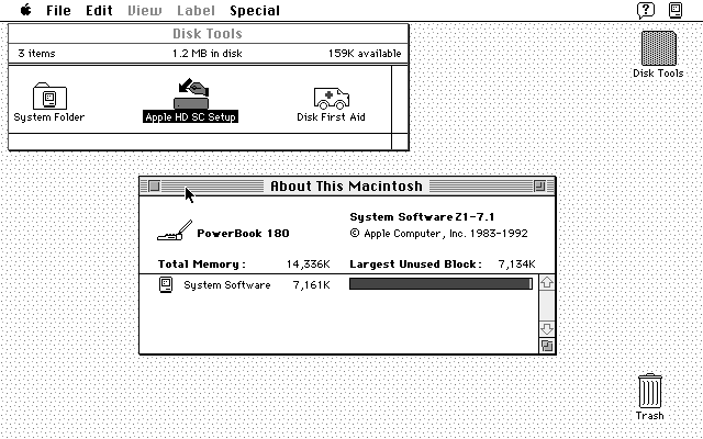
Seems I have two Macintosh PowerBook 180s: one has a dead colour screen but seems to boot fine, and the other (the one screenshotted above; yay ⌘+Shift+3 and enough room on the boot floppy …) has a lovely greyscale screen but a dead hard drive. I suspect we’re going to have to do a head transplant.
And no, I’m not having ¼-century 68030+68882 wish fulfillment one bit …
Building and installing the linapple-pie Apple IIe emulator is relatively easy on the Raspberry Pi:
sudo apt install libcurl4-openssl-dev libzip-dev zlib1g-dev libsdl1.2-dev libsdl-gfx1.2-dev libsdl-image1.2-dev libsdl-sound1.2-dev build-essential git
git clone https://github.com/dabonetn/linapple-pie.git
cd linapple-pie/src
make
sudo make install
This also works on an x86_64 Ubuntu machine. It does also install on a PocketCHIP (even if it takes a really long time) but I can’t get the display resolution to fit correctly.
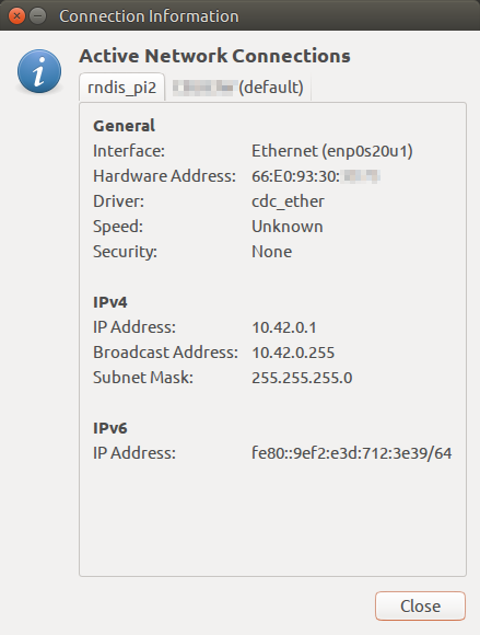
The Raspberry Pi Zero can be set up to appear as one of several USB OTG “gadgets†if you plug it into another computer. The most popular setting seems to be the virtual network gadget that turns your Zero into a computer on the end of your USB cable. Andrew Mulholland’s guide Raspberry Pi Zero – Programming over USB! (Part 2) (along with his super-short simple guide) seems to be the definitive source on how to set these modes up.
One problem, though, is that the Zero would show up on different network addresses every time it was restarted. The changing addresses made ssh access no fun at all. A suggestion on the Raspberry Pi forum helped me come up with a solution. On the Raspberry Pi Zero, run this command once:
This will set the USB port’s hardware addresses to a fixed value, and you should always get a connection on the same IP address if it’s available.
How my Raspberry Pi Zero appears on my Ubuntu machine
Update: For some reason, this seemed to stop working, and I was getting the old random addresses again. I was resisting putting more stuff in /boot/cmdline.txt, but it seems to me it’s more reliable than what I proposed. So if your g_ether.conf looked like:
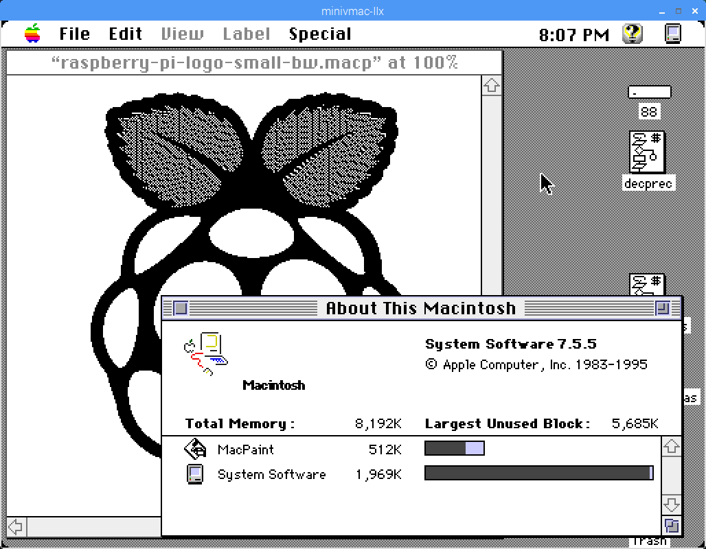
Running Mini vMac on a Raspberry Pi is hardly news. But maybe running it as a colour Mac II is. The screen size I’ve chosen is closer to a Color Classic, for no other reason that I like it.
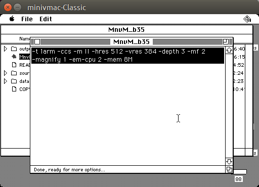
To build a Mac II-capable version of Mini vMac, you’ll need the Alpha source code. You’ll also need a working Mini vMac setup, as it uses a 68k Mac program to set up the source. Pretty much any basic setup and bootable disk will run this okay:
Mini vMac building on an emulated Mac Classic booting from the System 7 Network Access floppy image (no, I couldn’t boot from Classic’s hidden boot ROM disk)
I’ve chosen to swap the Ctrl key with the Command (⌘) key, as most non-Mac keyboards work better with this.
The build program will export a file out/minivmac-3.5.0-larm.tar that you can unpack into the full source code. It’s a really simple build, and fast, too.
Now you’ll need a Mac IIx ROM image (which I’m not supposed to help you find, but it’s an easy search) and OS image disks from the Mini vMac System Software page. Have fun!
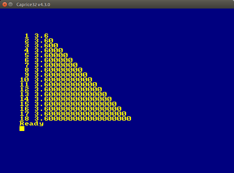
The program on the left is running on the decimal interpreter, the one on the right the regular one
Microsoft used to supply two versions of its BASIC for Macintosh. One used decimal mathematics for precise tallying of small amounts. The other used the more familiar floating point mathematics, rounding errors and all. I don’t know what floating point library Microsoft used for sure — perhaps Motorola’s 32-bit Fast Floating Point system — but it introduces rounding errors pretty quickly. Modern routines don’t start displaying oddly until after 15 decimal places.
Consider this simple program:
10 LET x=36/10
20 LET a$="## #.#"
30 FOR n%=1 TO 18
40 PRINT USING a$; n%; x
50 LET a$=a$+"#"
60 NEXT n%
70 END
Along with the number of decimal places, it should print 3.6, 3.60, 3.600, 3.6000, … with an increasing line of zeroes after the 3.6. Bas makes a valiant but typical attempt:
Immersive it ain’t, but you have to remember it was 1978 …
cbmbasic is pretty cool. It’s a portable C rendition of the Commodore 64’s ROM BASIC interpreter. While not the spiffiest version of the language, it does allow some very old code to run — such as the games from David H. Ahl’s book BASIC Computer Games.
Here are all the programs automatically converted to cbmbasic’s tokenized format: cbmbasic-Ahl-BASIC_Games. They seem to run, but some might fail. Notes on sources of the text files and conversion methods are in the archive. Have fun!
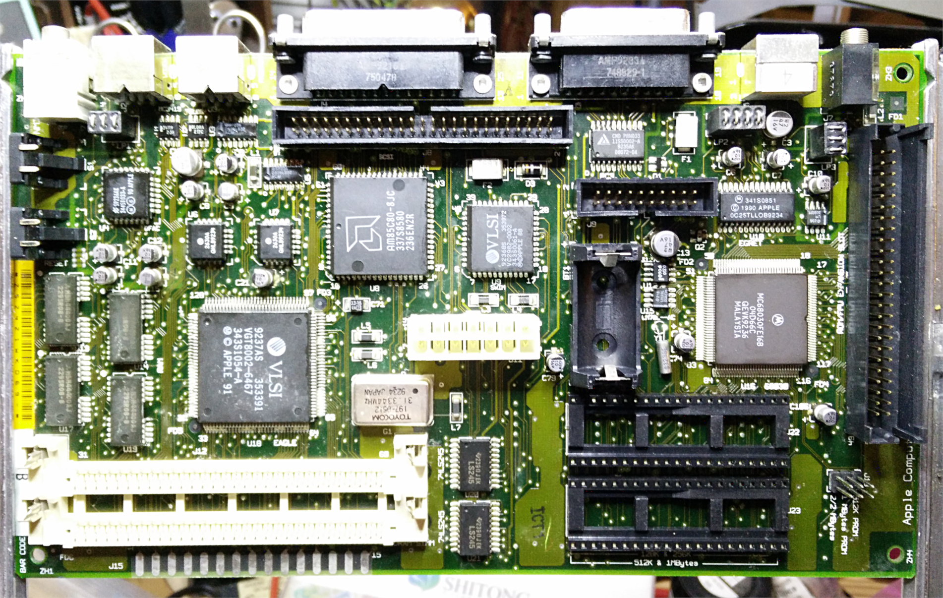
Since the 68kMLA wiki page on Capacitor Replacement doesn’t have it, and also doesn’t seem to be accepting new edits, here’s what you need to replace the leaky capacitors on a revision 2 Macintosh Classic II motherboard (part 820-0326-B):
You’ll probably also be looking for a 3.6 V ‘½ AA’/14250 lithium battery too, as if it hasn’t leaked in the 25 years since your Classic II was made it’ll be completely flat. These can be a bit pricey and hard to find. I got one at Sayal for nearly $10.
The revision 2 Classic II board is immediately identifiable by having only two ROM sockets where the first revision has four ROMs.
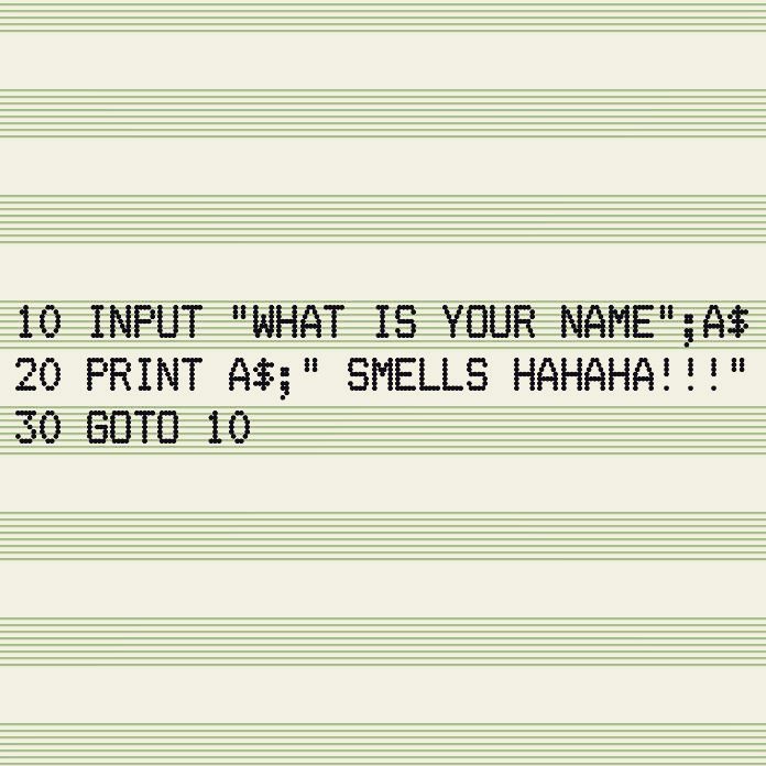
A quick throwaway dot-matrix printer lookalike. The font is Effects Eighty regular at 12 pt. The music-ruled/green bar fanfold paper simulation is something I smacked together quickly in Inkscape: fanfold-music.pdf
Update: this is old and, like most good things in X, likely has been broken by Wayland.
I wanted to have a “Hey, be here now!” ping throughout the working day. Something loud enough to hear, but not irritating.
Doing this with cron was harder than you might expect. It seems that sound is typically part of the X11 display infrastructure, so you need to give the command permission to make a noise on this particular machine’s display. Here’s the crontab line I came up with:
# m h    dom mon dow   command
  0 9-17 *   *   1-5   export DISPLAY=:0 && /usr/bin/play -q /home/scruss/sounds/ting/ting.wav
That translates as: at 0 minutes past the hours of 09:00 to 17:00 on any weekday (day of week = 1-5, and we don’t care about day of month or which month it is), execute the command play (part of the sox package) with no text output (-q). cron needs environment variables like DISPLAY set, and prefers full command paths. It may trigger a second or so after the turn of the hour; this is good enough for me.
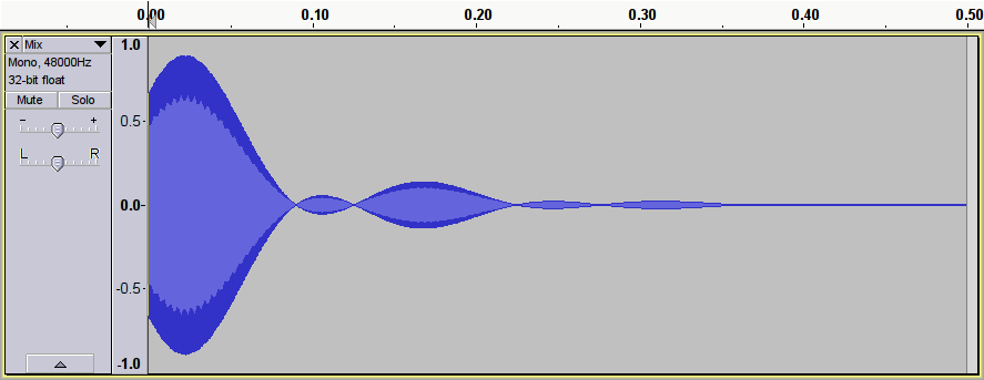
As for the alert, I wanted something distinctive — percussive, short, bright — but with a tiny bit of modulation to stop it sounding like a bland computer-generated sine wave. This is what I made; click on the image and the sound should play or download:
It’s essentially a 2093 Hz (C₇) sine wave, mixed with itself frequency-modulated at 7 Hz. Why 7 Hz? Apart from sounding about right, 2093 is exactly divisible by 7, 13 & 23, so I used a factor for neatness.
There was some later messing about in Audacity (mostly fades and length edits; I forget exactly what). The two components were generated using sox:
sox -n ting-plain.wav synth 1 sine C7 fade l 0 1 1
 sox -n ting-vibrato.wav synth 1 sin C7 synth 1 sine fmod 7 fade l 0 1 1
Yes, sox does have pretty horrible syntax, doesn’t it?
The frequency-modulated one seems to be pretty close to the final result. It would be less time spent trying to save time …
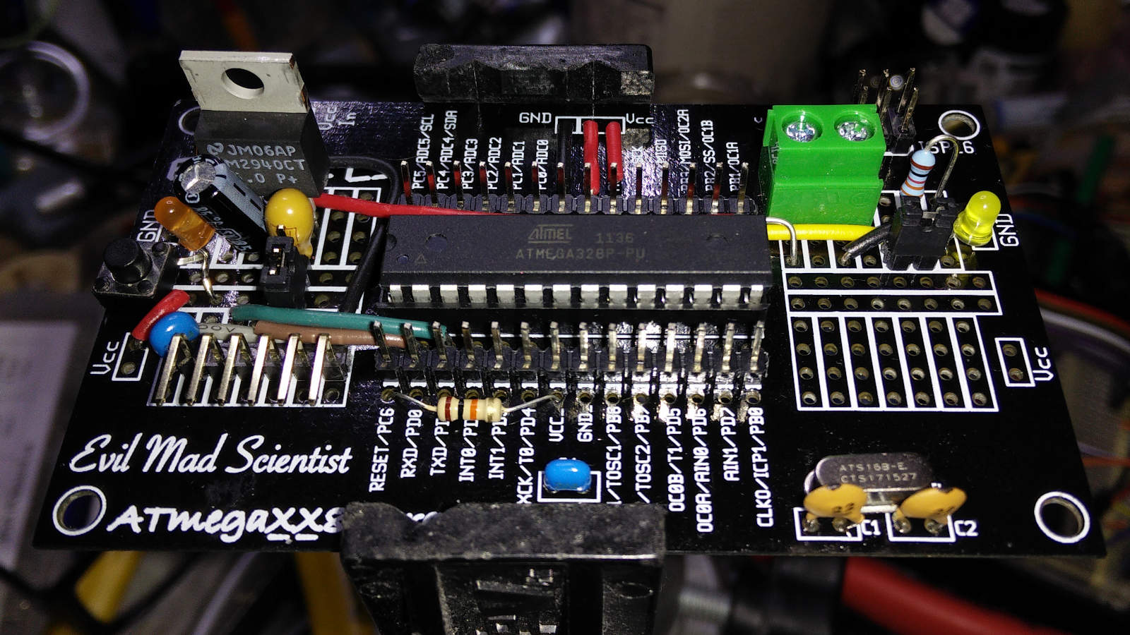
You could say I overthought this “minimal” ATmega328 µcontroller build: switchable USB/external power, reset button, optional D13 LED for your blink() needs, high efficiency LM2940 LDO voltage regulator …
In the age of cheap 32-bit microcontroller boards available for a couple of dollars, there’s absolutely no reason to build one of these semi-custom 8-bit Arduino clones. I did it because I had all (well, nearly all —the 0.33µF tantalum cap needed on the output side of the the regulator I bought in) the bits in the house, and I wanted to see how few connections a modern microcontroller really needed. Once I’d seen just how few, I thought I’d make this thing easy to use … and got a bit carried away.
I do kind of miss the diversity of form in the µc board market these days. Everything looks like an Arduino now. Tiny variants like the Solarbotics Ardweeny kept creative interest up. But with boards and chips so cheap these days, why bother?
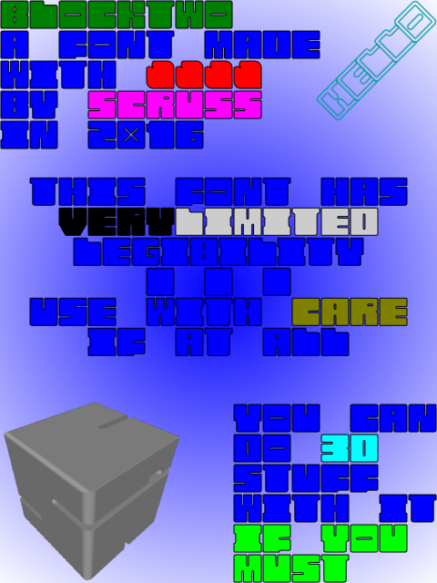
BlockTwo is a spectacularly ugly font mostly for playing about with 3D intersections in OpenSCAD. Not recommended for any but the most extreme display usage. Coverage is only A-Z caps, 0-9, heart and block.
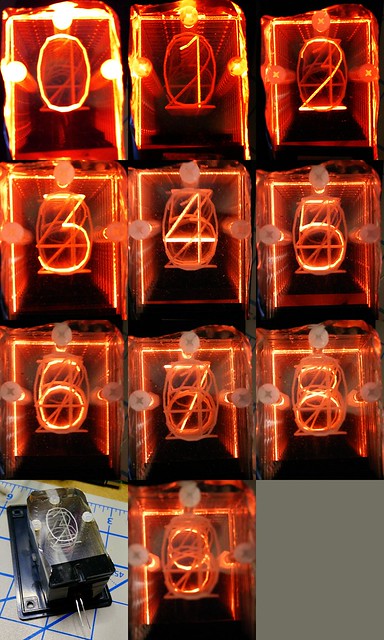
I want to make an edge-lit numeric display. These were a common technology before numeric LEDs were available. They use 10 illuminated slides to display individual numbers. Here’s my first try at the display:
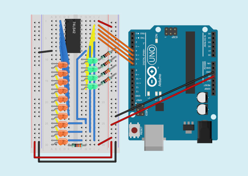
The 74LS42 logic chip (4-Line BCD to 10-Line Decimal Decoder) seems a likely candidate to drive such a display. You feed it a 4-bit binary-coded decimal input, and the chip activates one of ten outputs. It’s a low-voltage version of the old 7441 chip used for driving Nixie tubes. Here’s what I got working as a demo of the 7442, driven by an Arduino:
Because the 7442 will only activate one output at a time, it’s okay to use a single current-limiting resistor for all ten output LEDs. The chip also uses active low outputs: the outputs go from high to low when activated. The negative side of each LED goes to an output pin, and the chip sinks current when an output is selected, lighting the LED.
The components get in the way of seeing the wiring, so here’s another picture from Fritzing with just the wires and the breadboard:
Finally, here’s the Arduino sketch I wrote to drive the chip for the demo video. All it does is cycle through digital outputs 4–7, incrementing a bit every half second.
/*
   SeventyfourFortytwo - Arduino demo of a
   74LS42 - 4-line BCD to 10-line decimal decoder
   Steps through 0-15, two steps per second
   Shows the 74LS42's blocking of values 10-15 as invalid

   Wiring:
   Arduino  74LS42
   ======== =======
    4      - 15  Input A (bit 0)
    5      - 14  Input B (bit 1)
    6      - 13  Input C (bit 2)
    7      - 12  Input D (bit 3)

   scruss - 2016-09-23
*/

int n = 0;

void setup() {
  pinMode(4, OUTPUT);
  pinMode(5, OUTPUT);
  pinMode(6, OUTPUT);
  pinMode(7, OUTPUT);
  digitalWrite(4, LOW);
  digitalWrite(5, LOW);
  digitalWrite(6, LOW);
  digitalWrite(7, LOW);
}

void loop() {
  digitalWrite(4, n & 1);
  digitalWrite(5, n & 2);
  digitalWrite(6, n & 4);
  digitalWrite(7, n & 8);
  n++;
  if (n > 15) n = 0;
  delay(500);
}
If you felt really fancy, you could drive the LED inputs through PWM, and come up with just the right of flicker to make this look like a Nixie tube. You should also be able to chain the inputs through some shift registers, too.
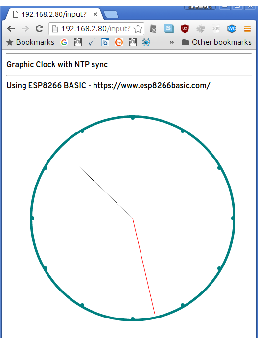
That picture might not look much, but it’s doing something rather wonderful. It’s a tiny ESP8266 BASIC script running on a super-cheap ESP8266 wifi module. The code draws a clock that’s synced to an NTP server. ESP8266 BASIC graphic commands are built from SVG, so anything you can draw on the screen can also be saved as a vector graphic:
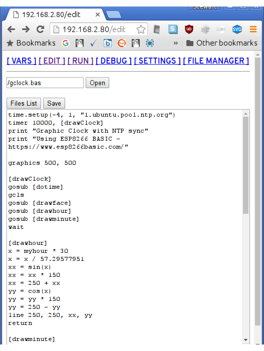
The runtime includes a simple textarea editor that saves code to the board’s flash:
(and yes, that first line is all you need to set up NTP sync)
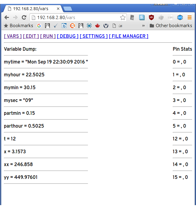
Among other features, ESP8266 BASIC has a simple but useful variable display:
I’d picked up a (possible knock-off of a)WeMos D1 ESP8266 board in Arduino form factor a few months ago. The Arduino.cc Software now supports ESP8266 directly, so it’s much easier to program. Flashing the BASIC code to the board was very simple, as I’d noticed that the Arduino IDE printed all of its commands to the console. All I needed to do was download an ESP8266 BASIC Binary, and then run a modified Arduino upload line from the terminal:
ESP8266 BASIC starts in wireless access point mode, so you’ll have to connect to the network it provides initially. Under Settings you can enter your normal network details, and it will join your wifi network on next reboot. I just hope it doesn’t wander around my network looking for things to steal …
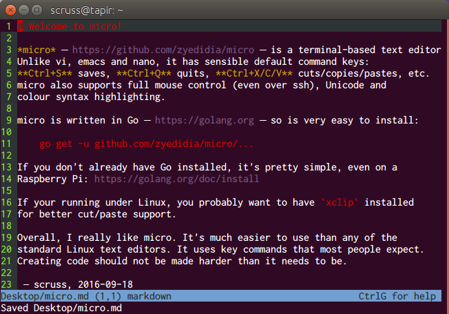
micro – https://github.com/zyedidia/micro – is a terminal-based text editor. Unlike vi, emacs and nano, it has sensible default command keys: Ctrl+S saves, Ctrl+Q quits, Ctrl+X/C/V cuts/copies/pastes, etc. micro also supports full mouse control (even over ssh), Unicode and colour syntax highlighting.
micro is written in Go – https://golang.org – so is very easy to install:
If your running under Linux, you probably want to have xclip installed for better cut/paste support.
Overall, I really like micro. It’s much easier to use than any of the standard Linux text editors. It uses key commands that most people expect. Creating code should not be made harder than it needs to be.
(I was about to suggest FTE, as it appears to be the closest thing to the old MS-DOS 6 editor that I’ve seen under Linux. While it’s a great plain text editor, its Unicode support isn’t where it needs to be in 2016.
micro suggestion came via MetaFilter’s Ctrl + Q to quit. Need I say more?)
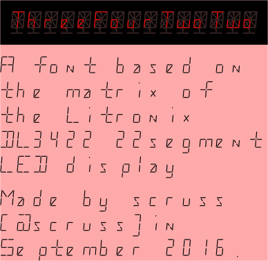
Yup, another highly impractical monospaced font. This one is based on a short-lived 22 segment display made in the early 1980s by Litronix (datasheet).
It’s hard to believe that Paul Carter has been gone ten years. I realized that my original ZX Spectrum BASIC memorial to him had got a bit dusty, in that it ran as an outdated Java applet. So I rewrote the code, and put it here: All the Colours We Have (for Paul Carter).
As Side Door sign v3 seemed to have fallen off, I needed to make a new one. With access to a laser cutter, I can make really permanent things now, so I designed this:
Yes, that’s a pointy thing filled with pointy things (all without thumbs, you’ll notice) and labelled with Cooper Black. Irony, much? Fe!
In order to get the sign to hang correctly, I needed to work out the centroid of the pointy outline. thedatachef/inkscape-centroid: Centroids for Inkscape paths and shapes to the rescue! Well, kinda. First off, the installer had a bug that said a Ruby file was a dependency when the plugin was in Python. So I forked the repo, made the change, tested it, and issued a pull request. So yay, working centroid calculations in Inkscape!
Secondly, the plugin only works well for simple shapes, like these:
But compound shapes? Not so well:
I guess it doesn’t like the negative moments generated by the holes, and does its own thing. Oh well.
 Seems I have two Macintosh PowerBook 180s: one has a dead colour screen but seems to boot fine, and the other (the one screenshotted above; yay ⌘+Shift+3 and enough room on the boot floppy …) has a lovely greyscale screen but a dead hard drive. I suspect we’re going to have to do a head transplant.
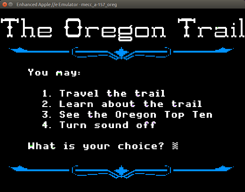


