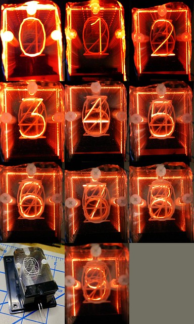
I want to make an edge-lit numeric display. These were a common technology before numeric LEDs were available. They use 10 illuminated slides to display individual numbers. Here’s my first try at the display:
 The 74LS42 logic chip (4-Line BCD to 10-Line Decimal Decoder) seems a likely candidate to drive such a display. You feed it a 4-bit binary-coded decimal input, and the chip activates one of ten outputs. It’s a low-voltage version of the old 7441 chip used for driving Nixie tubes. Here’s what I got working as a demo of the 7442, driven by an Arduino:
(Video link for the iframe-averse: https://www.youtube.com/watch?v=cETGB2M8iUw)
From the video you can see that:
- The 7442 only passes inputs from 0 (0000b) to 9 (1001b). All other inputs result in no output.
- The outputs are really more like 1–10 than 0–9, as a zero input activates the first output.
Making a clean breadboard layout for this circuit was a little more work than I’d anticipated. It just fits on a half-sized breadboard:
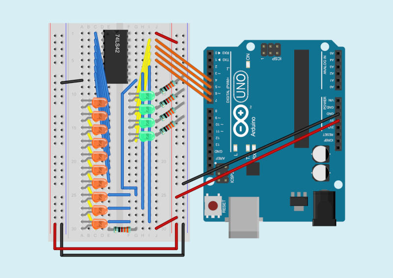
Because the 7442 will only activate one output at a time, it’s okay to use a single current-limiting resistor for all ten output LEDs. The chip also uses active low outputs: the outputs go from high to low when activated. The negative side of each LED goes to an output pin, and the chip sinks current when an output is selected, lighting the LED.
The components get in the way of seeing the wiring, so here’s another picture from Fritzing with just the wires and the breadboard:
 Apart from the 74LS42 chip itself, the components I used were 10× 3mm orange LEDs on the outputs and 4× 3mm green LEDs on the inputs. I don’t have a spec for them (they were from a bargain selection box from PCBoard.ca) so my use of ridiculously precise 332 Ω 1% resistors to limit current is a little unnecessary. (I have a bunch of these precision resistors from a project that didn’t go ahead, so using them is cheaper for me than digging about for a 5% one.)
Finally, here’s the Arduino sketch I wrote to drive the chip for the demo video. All it does is cycle through digital outputs 4–7, incrementing a bit every half second.
/*
   SeventyfourFortytwo - Arduino demo of a
   74LS42 - 4-line BCD to 10-line decimal decoder
   Steps through 0-15, two steps per second
   Shows the 74LS42's blocking of values 10-15 as invalid

   Wiring:
   Arduino  74LS42
   ======== =======
    4      - 15  Input A (bit 0)
    5      - 14  Input B (bit 1)
    6      - 13  Input C (bit 2)
    7      - 12  Input D (bit 3)

   scruss - 2016-09-23
*/

int n = 0;

void setup() {
  pinMode(4, OUTPUT);
  pinMode(5, OUTPUT);
  pinMode(6, OUTPUT);
  pinMode(7, OUTPUT);
  digitalWrite(4, LOW);
  digitalWrite(5, LOW);
  digitalWrite(6, LOW);
  digitalWrite(7, LOW);
}

void loop() {
  digitalWrite(4, n & 1);
  digitalWrite(5, n & 2);
  digitalWrite(6, n & 4);
  digitalWrite(7, n & 8);
  n++;
  if (n > 15) n = 0;
  delay(500);
}
If you felt really fancy, you could drive the LED inputs through PWM, and come up with just the right of flicker to make this look like a Nixie tube. You should also be able to chain the inputs through some shift registers, too.
Leave a Reply