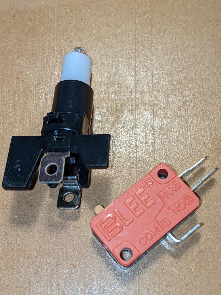
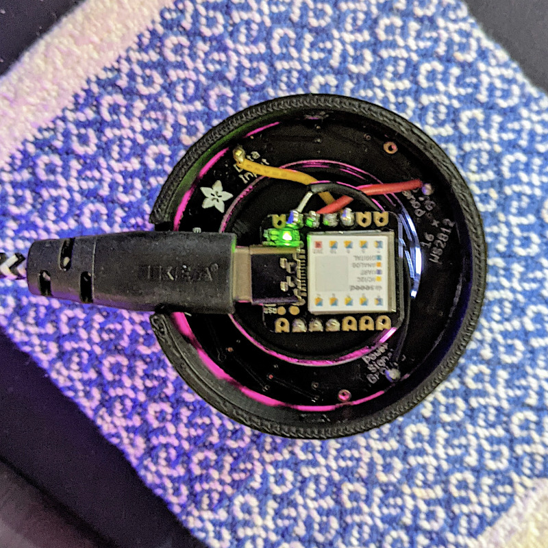
Following on from a customer query at Elmwood Electronics, I can confirm that one can install install addressable RGB LEDs/NeoPixels inside one of these large buttons. It’s not the easiest build, so whether one should attempt this is another matter entirely.
You’ll need:
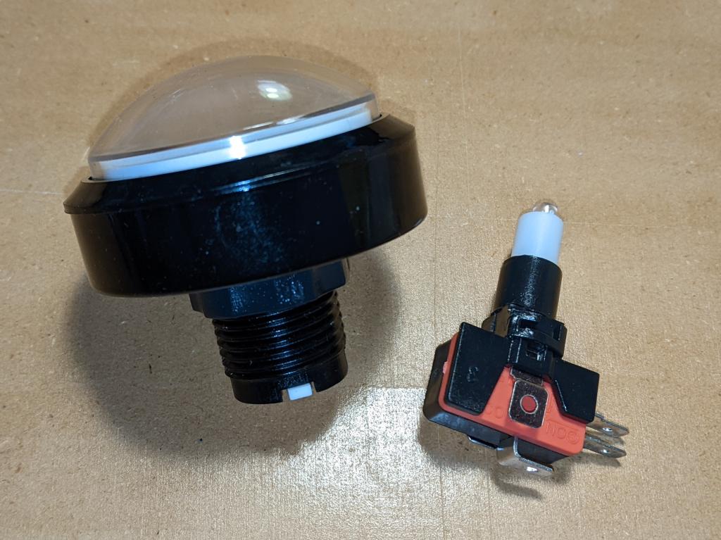
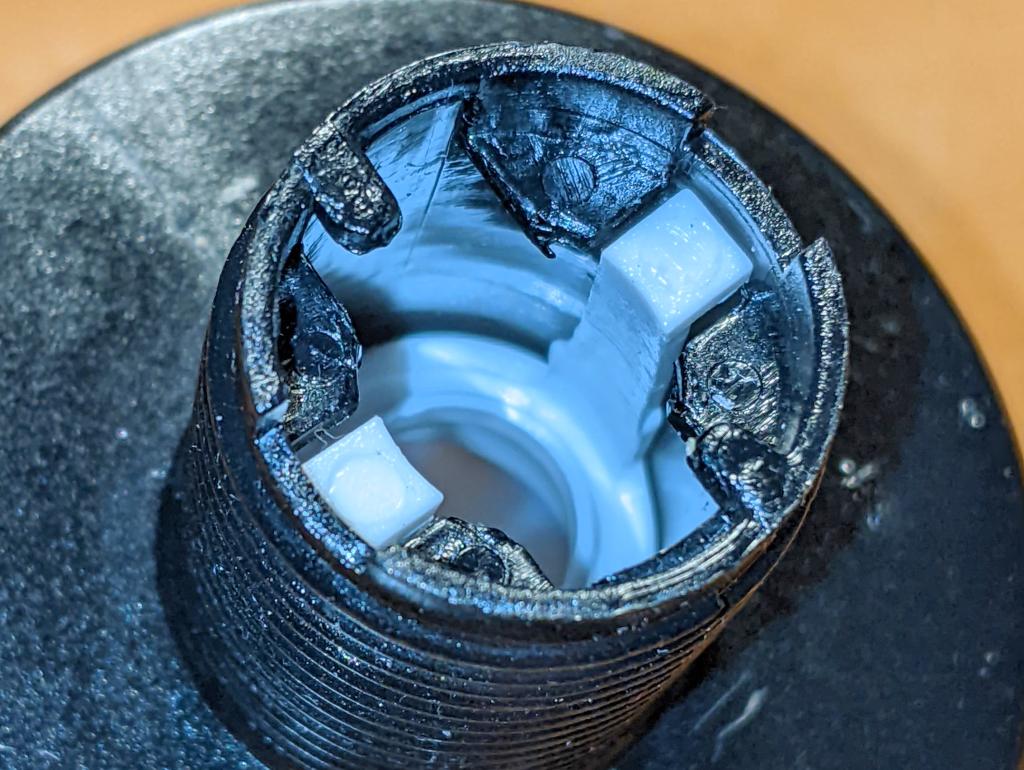
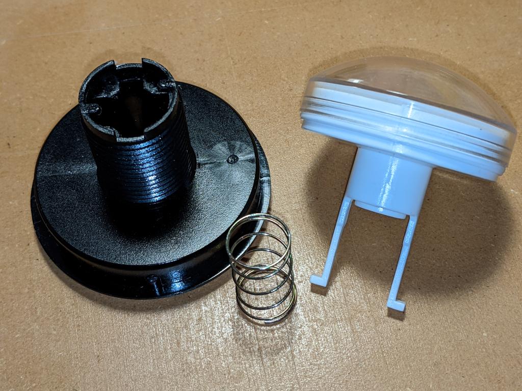
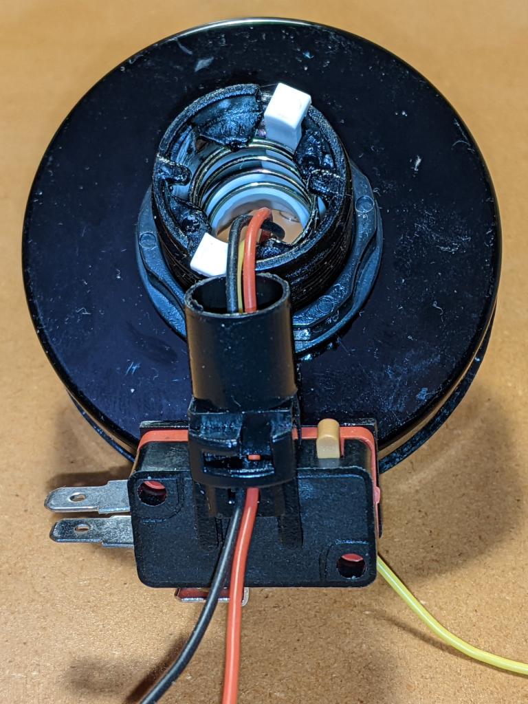
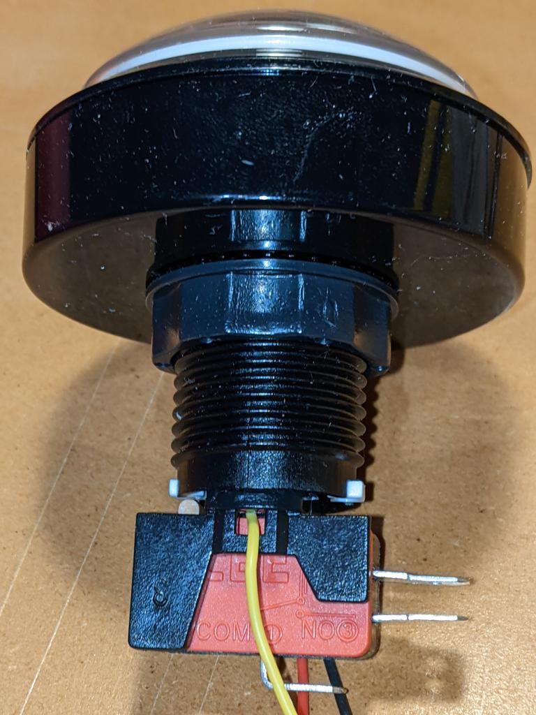
- Large Arcade Button with LED – 60 mm White (tall version) – this is larger and more domed than the flat-top one that Adafruit sells
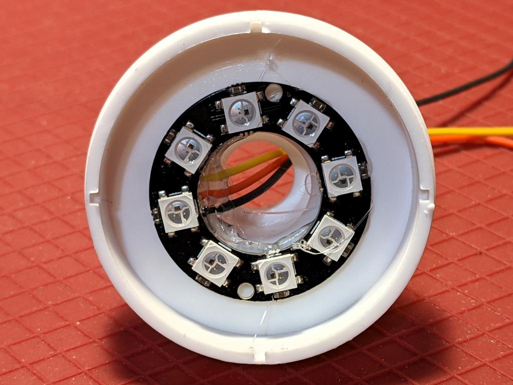
- RGB LEDs – I used a generic 8 LED ring, but anything not too tall and under 45 mm in diameter should fit. Either a 7 X WS2812 5050 RGB LED Ring or Adafruit’s NeoPixel Ring – 12 x WS2812 5050 RGB LED with Integrated Drivers could also work
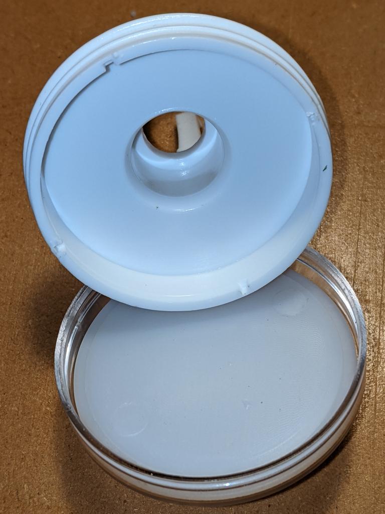
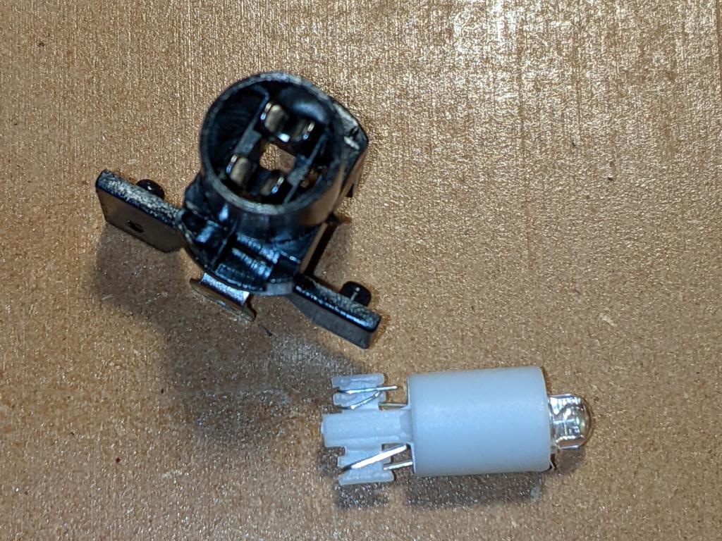
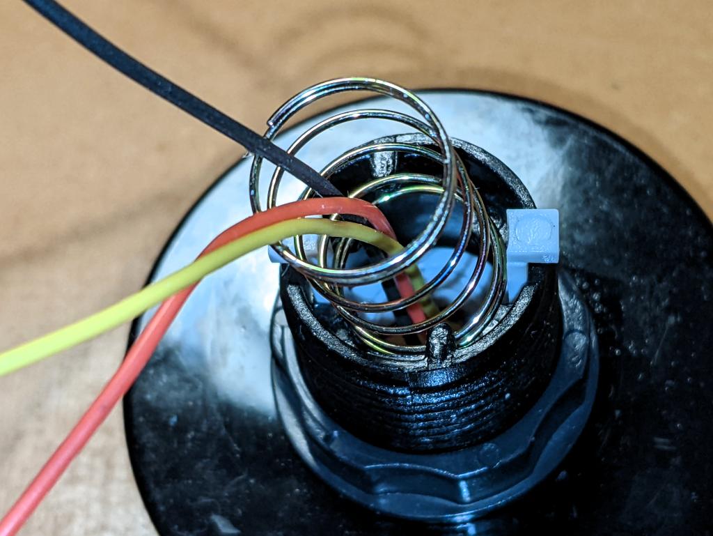
- Thin (and I mean thin: I used 28 AWG) Silicone Cover Stranded-Core Wire in several colours. You’ll want to cut this quite long at first, as you have to ease it through some tiny holes in the button assembly. If you solder connectors on the end, you won’t be able to disassemble or install the button without cutting them off. Do I speak from experience here? You betcha!
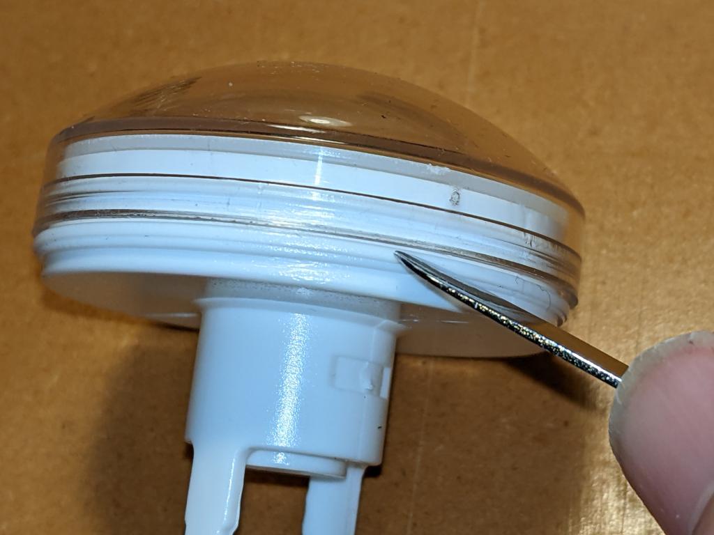
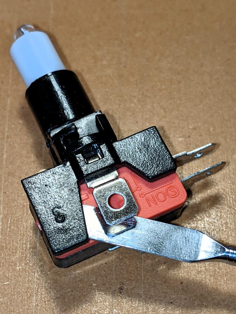
- The usual soldering/hot gluing/bending/prying/grabbing/cutting tools you already know and love. In addition, you might consider a non-marring spudger and a pair of small(ish) arterial forceps (aka hemostats, aka Kelly forceps, aka fishing hook removal pliers)
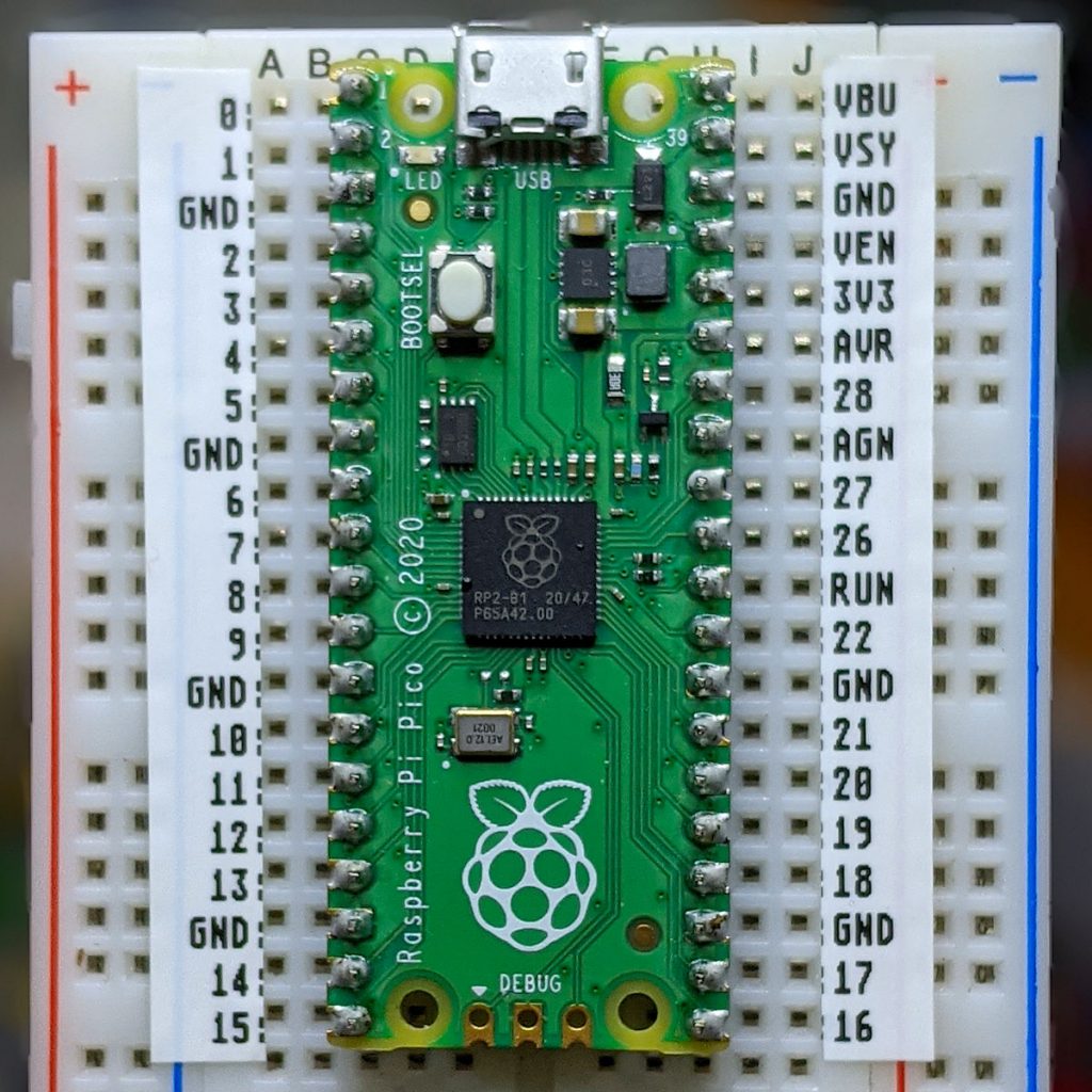
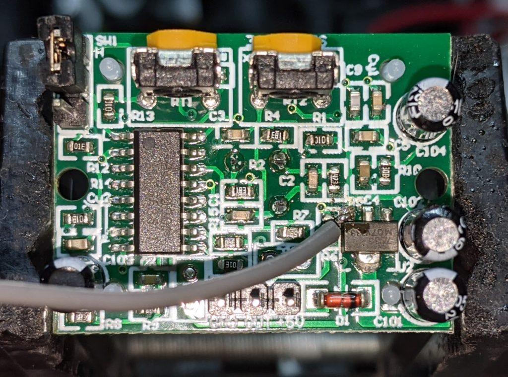
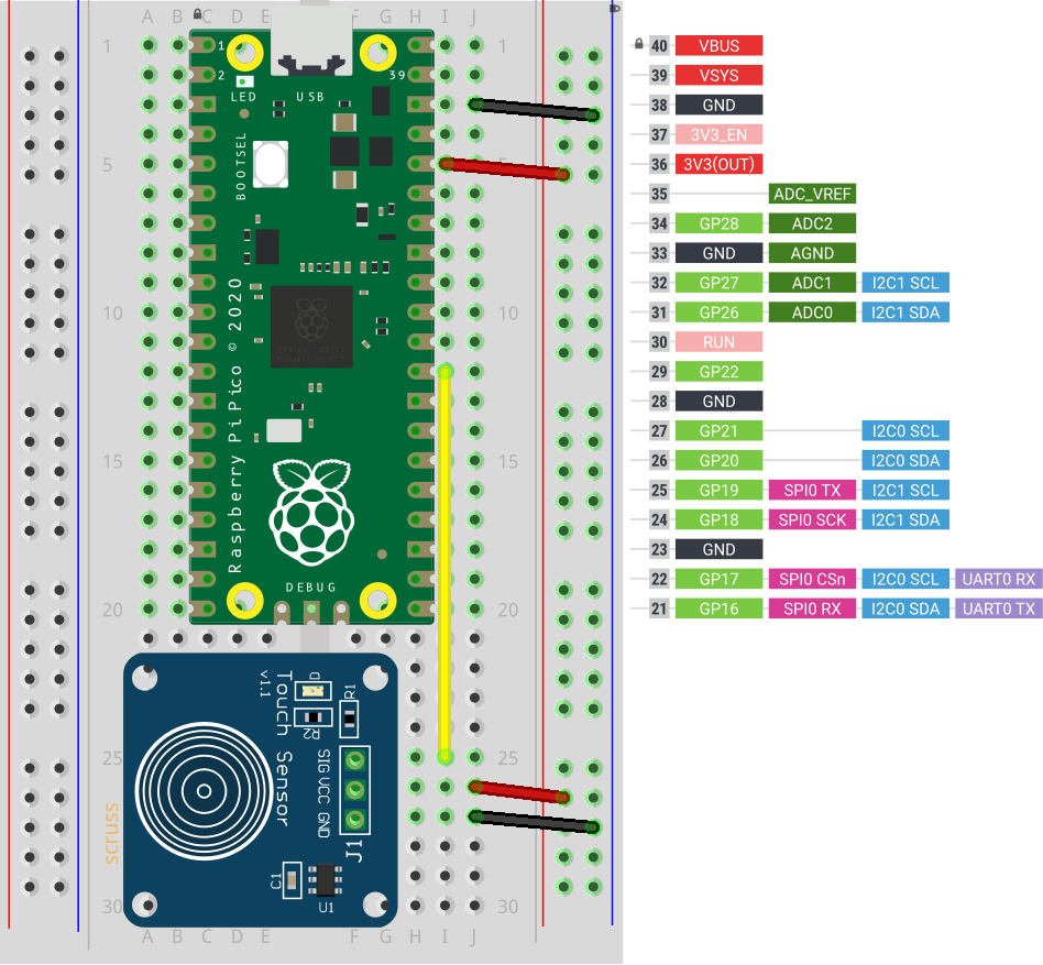
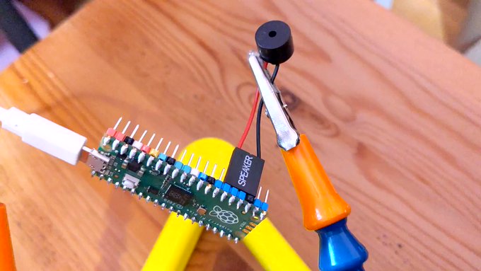
I’m not going to cover soldering the wires to the LED PCB in any depth here. You’ll need three wires: 5 V power, Ground and Data. Even though the LEDs I used need 5 V power, they are quite happy with 3.3 V logic on the data line. They need more than 3.3 V power to light, though.