that red is much more orange in daylight. Note 1964 copyright year …
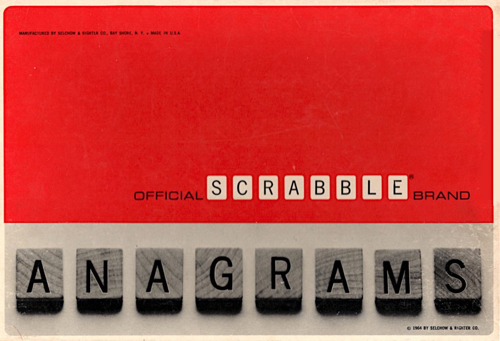
Found in a thrift store, the 1960s Selchow & Righter SCRABBLE® variant that nobody loved. It has no board, but 180 tiles, slightly different from the SCRABBLE® ones (dang, I love that I can type ®, can’t you tell?)
that Q, tho …
The stencilling/printing isn’t perfectly even in position, but I do have to remember these are at least 60 years old:
some variation in same letter placement
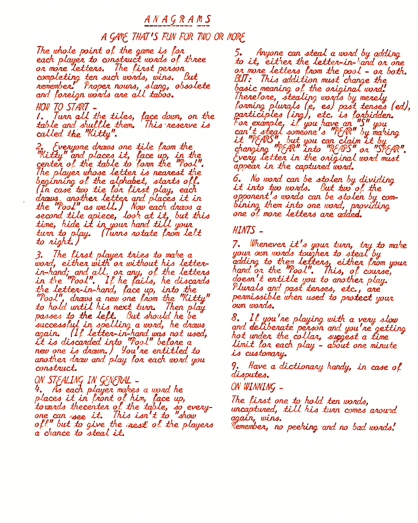
The instructions from inside the box (which were murder to scan btw: appreciate me!) are dated 1962, unlike the box. There’s a PDF linked under this image for those who enjoy legibility:
Included in the box, possibly original, is an instruction sheet typed in the naffest font known to man:
say you were typed on an early 1960s Smith-Corona Galaxie without saying, etc. …
Should you have no taste at all and want this excuse for type in your own documents, go here: zai Smith-Corona Galaxie Typewriter Font. May your documents smell of stale cigarette smoke forever. At least no-one will be able to OCR them.
The typed rules seem to disagree with the box rules a little. Pick the one you dislike less.
The 180 tiles have a slightly odd distribution for English: A×14, B×4, C×4, D×8, E×22, F×4, G×6, H×4, I×18, J×2, K×2, L×8, M×4, N×10, O×14, P×4, Q×2, R×12, S×8, T×10, U×8, V×2, W×2, X×2, Y×4, Z×2. You’re not going to make this up with any number of SCRABBLE® tile sets.
You can’t even make up a full 144 tile Bananagrams set with these. Even if you remove the excess tiles (A, B, C, D×2, E×4, F, G×2, H, I×6, L×3, M, N×2, O×3, P, R×3, S×2, T, U×2, Y), you’d still be short by a V and a W. A bug, perhaps?
Here are the rules from the box lid in full:
OFFICIAL SCRABBLE® BRAND ANAGRAMS
HOW TO PLAY ANAGRAMS
Of the many varieties of word games, Anagrams is one of the oldest and best known. The word Anagram means a word formed by rearranging the letters of a different word so as to completely change it. For example, the three letters of A, P, T can be combined to spell APT, TAP and PAT. These words are anagrams of one another. The game of Anagrams is a contest in forming words by combining letters drawn at random or by rearranging letters of words already formed.
This anagram set consists of 180 letters assorted in proportion to their frequency of use in forming words in the English language as computed by experts in analysis of word formations.
To Start:
Place all letters face down on a table. Shuffle them and arrange in approximately equal groups at the corners or sides of the table. (Or place them in a box or bowl from which they can be drawn conveniently one-by-one without being seen in advance.) Leave room in the center of the table for a dozen or more letters and clear a space in front of each player for the words that he will form.
Each player (2 to 6 make the best game) then draws one letter and places it face up in the center of the table. The player drawing the letter nearest the beginning of the alphabet wins first turn. Others follow him clockwise around the table. (In case of a tie for first turn, the tied players draw again until the tie is broken.)
If fewer than 10 letters have been turned up in the center of the table the player who has won first turn draws enough additional letters to make a total of 10 exposed letters on the table. For the remainder of the game the stock of exposed letters in the center of the table is replenished only by discards.
Word Formation:
The person who is taking his turn begins by drawing one concealed letter from any place on the table. This is his key letter. He tries to play it in one of the following three ways:
He may combine his key letter with 3 or more of the exposed letters from the center of the table to form a word of 4 or more letters. (For beginners use 3 or more letters.) If he can do so he places the word on the table in front of him and facing the center so that it is legible to all other players. (Note: He may not use letters from the center of the table to form a word which does not include his key letter.)
He may add his key letter (and one or more letters from the center of the table if possible) to enlarge or change one of his own words. For example, if his key letter is S and one of his own words is CARE, he may play the key letter to form CARES, RACES or SCARE; or he might play it and a T from the center of the table to form CARETS, CASTER, CRATES or TRACES.
He may steal a word previously formed by another player by adding his key letter (with one or more letters from the center of the table if possible) to form a new word in which the letters of the stolen word are rearranged. In the example used above he might steal the word CARE from another player by changing it to RACES, CASTER, CRATES or TRACES; he could not steal it to form CARES, CARETS or SCARE because the letters of the original word have not been rearranged.
Each player continues to draw and play key letters as long as he can use them in one of these three ways. If he draws a key letter that can not be played he discards it face up in the center of the table and his turn ends. The next player to the left then draws and begins his turn.
Challenging:
Before the game begins the players must agree on the types of words that will be used. Common practice is to use only words found in the alphabetical section of a standard dictionary excluding abbreviations, prefixes, suffixes, capitalized words and those requiring hyphens or apostrophes. These or other classes of words (such as geographical names) may be included by agreement. The important thing is to have a clear understanding before the game begins.
When a word is formed, changed or stolen during the game any other player or players may challenge it for spelling or other requirements that have been agreed upon. The word then must be found in the dictionary and verified. If it is correct the player retains the word and continues his turn; any player who has challenged a correct word loses his next turn. If the word can not be verified the letters are returned to the center of the board, to the original word or to the player from whom they were stolen, as the case may be; the person who attempted to form the word ends his turn at once and discards his key letter even though there might be other ways in which he could have used it.
A word may be challenged only at the time that it is played.
Penalty:
If a player, when drawing his key letter or at any other time after the play begins, exposes any concealed letter other than the key letter to which he is entitled, all letters so exposed are placed face up in the center of the table and the player loses the remainder of his turn or his next turn, as the case may be.
Scoring:
The game ends when one player has accumulated ten words or when the last concealed letter has been drawn, whichever occurs first. Scores then are counted by crediting each player with one point for each four-letter word and one additional point for each letter over four in any word.
COPYRIGHT 1962 BY SELCHOW & RIGHTER COMPANY, BAY SHORE, NEW YORK
Makers of PARCHEESI®, A Backgammon Game of India
Made in U.S.A.
The game is listed as Scrabble Scoring Anagrams on Board Game Geek and given a much later date (1972) than this one.
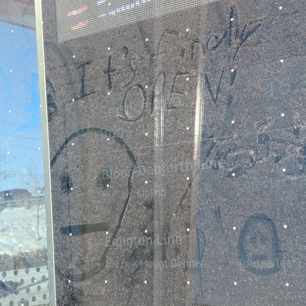
It’s years late and many millions over budget, but — at last — the TTC Line 5 Eglinton Crosstown is open today! I am slightly happy for them, as finally they’ll have to stop making excuses about why it’s closed.
I rode a little bit of it today (it was free) and this little bit of dust graffiti sums up how I feel
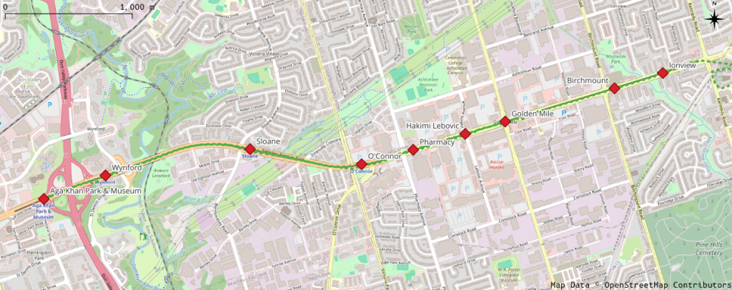
I rode the surface section from Kennedy to Aga Khan Park this afternoon, and my overall impression was: wow, this is really slow.
Map of Eglinton Avenue East, showing Crosstown stations from Aga Khan Park & Museum to Ionview
I was only able to track the train from Ionview, as my phone GPS is useless underground.
Westbound
I got on a westbound train a little after 15:30
Station
Distance / km
Arrive
Depart
Time
Speed / km/h
Ionview
15:37:20
Birchmount
0.552
15:39:05
15:39:40
1′ 45″
18.9
Golden Mile
1.244
15:42:37
15:42:39
2′ 57″
25.3
Hakimi Lebovic
0.455
15:44:29
15:44:30
1′ 50″
14.9
Pharmacy
0.592
15:47:55
15:48:30
3′ 25″
10.4
O’Connor
0.584
15:50:00
15:51:55
1′ 30″
23.3
Sloane
1.225
15:53:25
15:54:03
1′ 30″
49.0
Wynford
1.600
15:56:45
15:57:17
2′ 42″
35.5
Aga Khan Park & Museum
0.718
15:58:25
1′ 08″
38.0
Total
6.969
21′ 05″
19.8
Despite getting up to almost 50 km/h between O’Connor and Sloane, we still didn’t exceed an average of 20 km/h over the whole 7 km trip. So many stops for lights. Traffic on Eglinton was moving faster than us.
Eastbound
Two Alstom TTC/Metrolinx Crosstown light rail trains sit at the rather snowy Aga Khan Park station
I had to wait for 10 minutes at Aga Khan Park station for the return train. It was just a little brisk out. When it finally arrived, it was so busy that I ended up smushed against a door for most of the ride.
Station
Distance / km
Arrive
Depart
Time
Speed / km/h
Aga Khan Park & Museum
16:08:55
Wynford
0.718
16:10:10
16:11:00
1′ 15″
34.4
Sloane
1.600
16:14:00
16:14:45
3′ 00″
32.0
O’Connor
1.225
16:17:35
16:19:15
2′ 50″
25.9
Pharmacy
0.584
16:20:35
16:21:15
1′ 20″
26.3
Hakimi Lebovic
0.592
16:23:10
16:23:30
1′ 55″
18.5
Golden Mile
0.455
16:25:52
16:25:54
2′ 22″
11.5
Birchmount
1.244
16:29:50
16:30:25
3′ 56″
19.0
Ionview
0.552
16:31:35
1′ 10″
28.4
Total
6.969
22′ 40″
18.4
Even slower coming back.
It’s okay, TTC/Metrolinx: we’ve got used to waiting.
teleprinter tape glued to index card, 15 × 10 cm, paper/card/highlighter pencils (2025)
This is the only surviving fragment of The Epic of Mitorzp. It was transmitted by an unknown intelligence, but discarded by human operators as mere line noise.
HE F=RIDZT GOT
   T BAZU N LH EENGER COULDDARA=
 LSEEWTARM. = LISON =ASWHJDOO ZAS ZETH
  MI=TI ZEAC OS B=PN LLHERE T-R=RS
=WE=Z=PNS=E M HIZI VALD R G M
    M ANT =ART=H MITORZP PBTHAT L
   EEUEB XTAZ=ECL EELING F OMB=
     ICKSAWN=LTO HIS ENZ=
Who was Mitorzp? A hero? An outcast? We will never know. This tiny remnant can only hint at the colossal magnitude of the lost epic.
this image is supposed to be made almost entirely of sextant blocks, the Unicode characters around U+1FB00 – U+1FB1E made out of two columns of three blocks. They’re originally from broadcast teletext, and were made to build low-resolution images on a text screen
Making the pixel to character map is quite tricky. The Sextant character block isn’t contiguous, and it’s not in the order we need. It’s also missing four characters: empty block, full block, left half block and right half block. These have to be pulled in from other Unicode blocks.
This is the map I came up with, from 0–63 with LSB at bottom right and MSB at top left:
If you have a Wemos/LOLIN S3 MINI PRO board, you might find that firmware images don’t flash so well. That’s because the ESP32-S3FH4R2 has 4 MB of flash storage, and most ESP32-S3 boards have 8 MB.
This trims down a standard MicroPython ESP32-S3 firmware from a 4 MB filesystem partition down to 2 MB, and sets the overall flash size to 4 MB. Upload that to your board, and all will be well.
Alternatively, v1.26 supports “4MiB and larger” flash chips. I have confirmed that ESP32_GENERIC_S3-20250724-v1.26.0-preview.bin works as expected:
$ mpremote a1 run boardstats.py
Board       : Generic ESP32S3 module with ESP32S3
Frequency   : 160 MHz
Free Memory : 2061232
File storage: 2036 / 2048 K
Martin Raynsford / Solarbotics Solar Marble Machine loving glare off deep snow
Still going strong after more than a decade in the front window, the Solar Marble Machine has been running flat out all day because of the glare from the deep snow outside. It might normally do one click a day, if any at all.
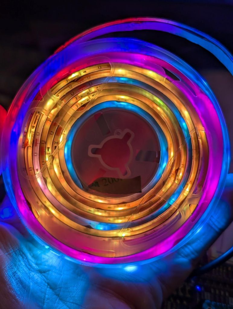
also known as “Monster BASICS Sound reactive RGB+IC Color Flow LED strip”. It’s $5 or so at Dollarama, and includes a USB cable for power and a remote control. It’s two metres long and includes 60 RGB LEDs. Are these really super-cheap NeoPixel clones?
I’m going to keep the USB power so I can power it from a power bank, but otherwise convert it to a string of smart LEDs. We lose the remote control capability.
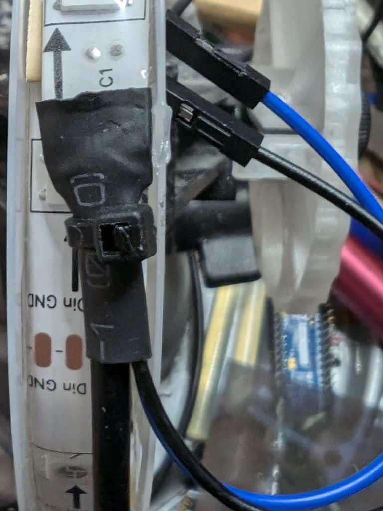
Pull back the heatshrink at the USB end:
… and there are our connectors. We want to disconnect the blue Din (Data In) line from the built in controller, and solder new wires to Din and GND to run from a microcontroller board.
Maybe not the best solder job, but there are new wires feeding through the heatshrink and soldered onto the strip.
Here’s the heatshrink pushed back, and everything secured with a cable tie.
Now to feed it from standard MicroPython NeoPixel code, suitably jazzed up for 60 pixels.
Stewart Russell – scruss.com — 2024-03-26, at age 19999 days …
Summary
One’s thousand day(s) celebration occurs every thousand days of a person’s life. They are meant to be a recognition of getting this far, and are celebrated at the person’s own discretion.
Who is this for?
Maybe your birthday’s on a day associated with an unpleasant event. Your thousand day will never coincide with your birthday.
Maybe your birthday’s in the middle of winter, or in another part of the year that you’re not keen on. Your thousand day is every 2 years and 3 seasons, so it shifts back by a season every time it happens.
Quantities and scale
1000 days is approximately:
2.738 years
2 years 269 days
2 years 8.85 months
2 years, 3 seasons.
4000 days is just shy of 11 years.
Disadvantages
Compared to regular birthdays, thousand days:
must be calculated; they’re not intuitive when they’re going to happen. But we have computers and calendar reminders for that …
can be used to work out your actual date of birth, if someone knows that you’re going to be x000 days old on a particular day. It’s possible to know someone’s birthday, but not know their age.
There are no trademarks, patents, official websites, social media or official anythings attached to this concept. Please take the idea and do good with it.
So why aren’t you implementing this further?
I’ve had this idea kicking around my head for at least the last 20 years. For $REASONS, it turns out I’m not very good at implementing stuff. I’d far rather someone else took this idea and ran with it than let it sit undeveloped.
This is a mini celebratory post to say that I’ve fixed the database encoding problems on this blog. It looks like I will have to go through the posts manually to correct the errors still, but at least I can enter, store and display UTF-8 characters as expected.
“? µ ° × — – ½ ¾ £ é?êè”, he said with some relief.
Postmortem: For reasons I cannot explain or remember, the database on this blog flipped to an archaic character set: latin1, aka ISO/IEC 8859-1. A partial fix was effected by downloading the entire site’s database backup, and changing all the following references in the SQL:
For additional annoyance, the entire SQL dump was too big to load back into phpmyadmin, so I had to split it by table. Thank goodness for awk!
#!/usr/bin/awk -f

BEGIN {
    outfile = "nothing.sql";
}

/^# Table: / {
    # very special comment in WP backup that introduces a new table
    # last field is table_name,
    # which we use to create table_name.sql
    t = $NF
    gsub(/`/, "", t);
    outfile = t ".sql";
}

{
    print > outfile;
}
The data still appears to be confused. For example, in the post Compose yourself, Raspberry Pi!, what should appear as “That little key marked “Compose”” appears as “That little key marked “Composeâ€Â”. This isn’t a straight conversion of one character set to another. It appears to have been double-encoded, and wrongly too.
Still, at least I can now write again and have whatever new things I make turn up the way I like. Editing 20 years of blog posts awaits … zzz
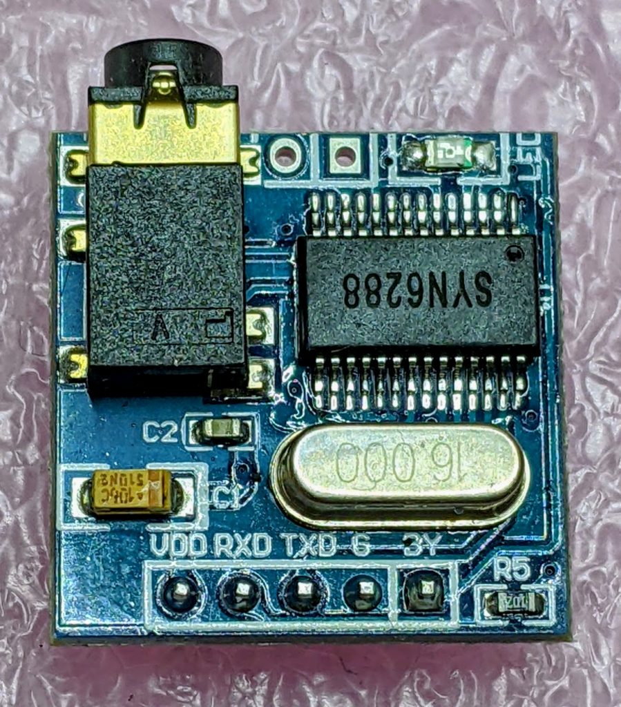
After remarkable success with the SYN-6988 TTS module, then somewhat less success with the SYN-6658 and other modules, I didn’t hold out much hope for the YuTone SYN-6288, which – while boasting a load of background tunes that could play over speech – can only convert Chinese text to speech
The wiring is similar to the SYN-6988: a serial UART connection at 9600 baud, plus a Busy (BY) line to signal when the chip is busy. The serial protocol is slightly more complicated, as the SYN-6288 requires a checksum byte at the end.
As I’m not interested in the text-to-speech output itself, here’s a MicroPython script to play all of the sounds:
# very crude MicroPython demo of SYN6288 TTS chip
# scruss, 2023-07
import machine
import time

### setup device
ser = machine.UART(
    0, baudrate=9600, bits=8, parity=None, stop=1
)  # tx=Pin(0), rx=Pin(1)

busyPin = machine.Pin(2, machine.Pin.IN, machine.Pin.PULL_UP)


def sendspeak(u2, data, busy):
    # modified from https://github.com/TPYBoard/TPYBoard_lib/
    # u2 = UART(uart, baud)
    eec = 0
    buf = [0xFD, 0x00, 0, 0x01, 0x01]
    # buf = [0xFD, 0x00, 0, 0x01, 0x79]  # plays with bg music 15
    buf[2] = len(data) + 3
    buf += list(bytearray(data, "utf-8"))
    for i in range(len(buf)):
        eec ^= int(buf[i])
    buf.append(eec)
    u2.write(bytearray(buf))
    while busy.value() != True:
        # wait for busy line to go high
        time.sleep_ms(5)
    while busy.value() == True:
        # wait for it to finish
        time.sleep_ms(5)


for s in "abcdefghijklmnopqrstuvwxy":
    playstr = "[v10][x1]sound" + s
    print(playstr)
    sendspeak(ser, playstr, busyPin)
    time.sleep(2)

for s in "abcdefgh":
    playstr = "[v10][x1]msg" + s
    print(playstr)
    sendspeak(ser, playstr, busyPin)
    time.sleep(2)

for s in "abcdefghijklmno":
    playstr = "[v10][x1]ring" + s
    print(playstr)
    sendspeak(ser, playstr, busyPin)
    time.sleep(2)
Each sound starts and stops with a very loud click, and the sound quality is not great. I couldn’t get a good recording of the sounds (some of which of which are over a minute long) as the only way I could get reliable audio output was through tiny headphones. Any recording came out hopelessly distorted:
I’m not too disappointed that this didn’t work well. I now know that the SYN-6988 is the good one to get. It also looks like I may never get to try the XFS5152CE speech synthesizer board: AliExpress has cancelled my shipment for no reason. It’s supposed to have some English TTS function, even if quite limited.
Here’s the auto-translated SYN-6288 manual, if you do end up finding a use for the thing
I have a bunch of other boards on order to see if the other chips (SYN6288, SYN6658, XF5152) work in the same way. I really wonder which I’ll end up receiving!
Update (2023-07-09): Got the SYN6658. It does not support English TTS and thus is not recommended. It does have some cool sounds, though.
Embedded Text Command Sound Table
The github repo references Embedded text commands, but all of the sound references were too difficult to paste into a table there. So here are all of the ones that the SYN-6988 knows about:
Name is the string you use to play the sound, eg: [x1]sound101
Alias is an alternative name by which you can call some of the sounds. This is for better compatibility with the SYN6288 apparently. So [x1]sound101 is exactly the same as specifying [x1]sounda
Type is the sound description from the manual. Many of these are blank
Link is a playable link for a recording of the sound.
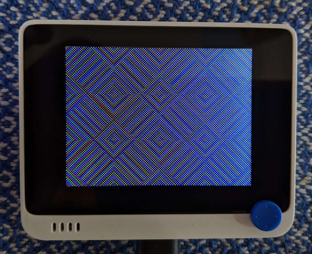
A while back, Seeed Studio sent me one of their Wio Terminal devices to review. It was pretty neat, but being limited to using Arduino to access all of it features was a little limiting. I still liked it, though, and wrote about it here: SeeedStudio Wio Terminal
Wio Terminal, doing a thing
There wasn’t any proper MicroPython support for the device as it used a MicroChip/Atmel SAMD51 ARM® Cortex®-M4 micro-controller. But since I wrote the review, one developer (robert-hh) has worked almost entirely solo to make SAMD51 and SAMD21 support useful in mainline MicroPython.
Hey! Development is still somewhere between “not quite ready for prime time” and “beware of the leopard”. MicroPython on the SAMD51 works remarkably well for supported boards, but don’t expect this to be beginner-friendly yet.
I thought I’d revisit the Wio Terminal and see what I could do using a nightly build (downloaded from Downloads – Wio Terminal D51R – MicroPython). Turns out, most of the board works really well!
What doesn’t work yet
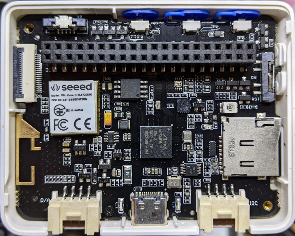
Networking/Bluetooth – this is never going to be easy, especially with Seeed Studio using a separate RTL8720 SoC. It may not be entirely impossible, as previously thought, but so far, wifi support seems quite far away
RTC – this is a compile-time option, but isn’t available on the stock images. Not all SAMD51 boards have a separate RTC oscillator, and deriving the RTC from the system oscillator would be quite wobbly. RTC works now! It may even be possible to provide backup battery power and have it keep time when powered off. VBAT / PB03 / SPI_SCK is broken out to the 40-pin connector.
What does work
Display – ILI9341 320×240 px, RGB565 via SPI
Accelerometer – LIS3DHTR via I²C
Microphone – analogue
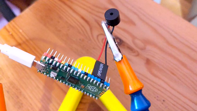
Speaker – more like a buzzer, but this little PWM speaker element does allow you to play sounds
Light Sensor – via analogue photo diode
IR emitter – PWM, not tied to any hardware protocol
Internal LED – a rather faint blue thing, but useful for low-key signalling
Micro SD Card – vi SPI. Works well with MicroPython’s built-in virtual file systems
Switches and buttons – three buttons on the top, and a five-way mini-joystick
I²C via Grove Connector – a second, separate I²C channel.
I’ll go through each of these here, complete with a small working example.
Inside the remarkably hard-to-open Wio Terminal
LED
Let’s start with the simplest feature: the tiny blue LED hidden inside the case. You can barely see this, but it glows out around the USB C connector on the bottom of the case.
MicroPython interfaces: machine.Pin, machine.PWM
Control pin: Pin(“LED_BLUE”) or Pin(15), or Pin(“PA15”): any one of these would work.
# MicroPython / Seeed Wio Terminal / SAMD51
# Wio-Terminal-LED.py - blink the internal blue LED
# scruss, 2022-10
# -*- coding: utf-8 -*-

from machine import Pin
from time import sleep_ms

led = Pin("LED_BLUE", Pin.OUT)  # or Pin(15) or Pin("PA15")

try:
    while True:
        led.value(not led.value())
        sleep_ms(1200)
except:
    led.value(0)  # turn it off if user quits
    exit()
IR LED
I don’t have any useful applications of the IR LED for device control, so check out Awesome MicroPython’s IR section for a library that would work for you.
# MicroPython / Seeed Wio Terminal / SAMD51
# Wio-Terminal-IR_LED.py - blink the internal IR LED
# scruss, 2022-10
# -*- coding: utf-8 -*-

# Hey! This is a completely futile exercise, unless you're able
# to see into the IR spectrum. But we're here to show you the pin
# specification to use. For actual useful libraries to do stuff with
# IR, take a look on https://awesome-micropython.com/#ir

# So this is a boring blink, 'cos we're keeping it short here.
# You might be able to see the LED (faintly) with your phone camera

from machine import Pin, PWM
from time import sleep_ms

ir = PWM(Pin("PB31"))  # "IR_CTL" not currently defined

try:
    while True:
        ir.duty_u16(32767)  # 50% duty
        ir.freq(38000)  # fast flicker
        sleep_ms(1200)
        ir.duty_u16(0)  # off
        sleep_ms(1200)
except:
    ir.duty_u16(0)  # turn it off if user quits
    exit()
Buttons
There are three buttons on top, plus a 5-way joystick on the front. Their logic is inverted, so they read 0 when pressed, 1 when not. It’s probably best to use machine.Signal with these to make operation more, well, logical.
Control pins: Pin(“BUTTON_3”) or Pin(92) or Pin(PC28) – top left; Pin(“BUTTON_2”) or Pin(91) or Pin(PC27) – top middle; Pin(“BUTTON_1”) or Pin(90) or Pin(PC26) – top right; Pin(“SWITCH_B”) or Pin(108) or Pin(PD12) – joystick left; Pin(“SWITCH_Y”) or Pin(105) or Pin(PD09) – joystick right; Pin(“SWITCH_U”) or Pin(116) or Pin(PD20) – joystick up; Pin(“SWITCH_X”) or Pin(104) or Pin(PD08) – joystick down; Pin(“SWITCH_Z”) or Pin(106) or Pin(PD10) – joystick button
# MicroPython / Seeed Wio Terminal / SAMD51
# Wio-Terminal-Buttons.py - test the buttons
# scruss, 2022-10
# -*- coding: utf-8 -*-

# using Signal because button sense is inverted: 1 = off, 0 = on
from machine import Pin, Signal
from time import sleep_ms

pin_names = [
    "BUTTON_3",  # Pin(92)  or Pin(PC28) - top left
    "BUTTON_2",  # Pin(91)  or Pin(PC27) - top middle
    "BUTTON_1",  # Pin(90)  or Pin(PC26) - top right
    "SWITCH_B",  # Pin(108) or Pin(PD12) - joystick left
    "SWITCH_Y",  # Pin(105) or Pin(PD09) - joystick right
    "SWITCH_U",  # Pin(116) or Pin(PD20) - joystick up
    "SWITCH_X",  # Pin(104) or Pin(PD08) - joystick down
    "SWITCH_Z",  # Pin(106) or Pin(PD10) - joystick button
]

pins = [None] * len(pin_names)
for i, name in enumerate(pin_names):
    pins[i] = Signal(Pin(name, Pin.IN), invert=True)

while True:
    for i in range(len(pin_names)):
        print(pins[i].value(), end="")
    print()
    sleep_ms(100)
Buzzer
A very quiet little PWM speaker.
MicroPython interfaces: machine.PWM
Control pin: Pin(“BUZZER”) or Pin(107) or Pin(“PD11”)
# MicroPython / Seeed Wio Terminal / SAMD51
# Wio-Terminal-Microphone.py - print values from the microphone
# scruss, 2022-10
# -*- coding: utf-8 -*-

from time import sleep_ms
from machine import ADC

mic = ADC("MIC")

while True:
    print([mic.read_u16()])
    sleep_ms(5)
Grove I²C Port
The Wio Terminal has two Grove ports: the one on the left (under the speaker port) is an I²C port. As I don’t know what you’ll be plugging in there, this example does a simple bus scan. You could make a, appalling typewriter if you really wanted.
# MicroPython / Seeed Wio Terminal / SAMD51
# Wio-Terminal-Grove-I2C.py - show how to connect on Grove I2C
# scruss, 2022-10
# -*- coding: utf-8 -*-

from machine import Pin, I2C

# NB: This doesn't do much of anything except list what's
# connected to the left (I²C) Grove connector on the Wio Terminal

i2c = I2C(3, scl=Pin("SCL1"), sda=Pin("SDA1"))
devices = i2c.scan()

if len(devices) == 0:
    print("No I²C devices connected to Grove port.")
else:
    print("Found these I²C devices on the Grove port:")
    for n, id in enumerate(devices):
        print(" device", n, ": ID", id, "(hex:", hex(id) + ")")
LIS3DH Accelerometer
This is also an I²C device, but connected to a different port (both logically and physically) than the Grove one.
Library: from MicroPython-LIS3DH, copy lis3dh.py to the Wio Terminal’s small file system. Better yet, compile it to mpy using mpy-cross to save even more space before you copy it across
# MicroPython / Seeed Wio Terminal / SAMD51
# Wio-Terminal-Accelerometer.py - test out accelerometer
# scruss, 2022-10
# -*- coding: utf-8 -*-
# based on
#  https://github.com/tinypico/tinypico-micropython/tree/master/lis3dh%20library

import lis3dh, time, math
from machine import Pin, I2C

i2c = I2C(4, scl=Pin("SCL0"), sda=Pin("SDA0"))
imu = lis3dh.LIS3DH_I2C(i2c)

last_convert_time = 0
convert_interval = 100  # ms
pitch = 0
roll = 0

# Convert acceleration to Pitch and Roll
def convert_accell_rotation(vec):
    x_Buff = vec[0]  # x
    y_Buff = vec[1]  # y
    z_Buff = vec[2]  # z

    global last_convert_time, convert_interval, roll, pitch

    # We only want to re-process the values every 100 ms
    if last_convert_time < time.ticks_ms():
        last_convert_time = time.ticks_ms() + convert_interval

        roll = math.atan2(y_Buff, z_Buff) * 57.3
        pitch = (
            math.atan2((-x_Buff), math.sqrt(y_Buff * y_Buff + z_Buff * z_Buff)) * 57.3
        )

    # Return the current values in roll and pitch
    return (roll, pitch)


# If we have found the LIS3DH
if imu.device_check():
    # Set range of accelerometer (can be RANGE_2_G, RANGE_4_G, RANGE_8_G or RANGE_16_G).
    imu.range = lis3dh.RANGE_2_G

    # Loop forever printing values
    while True:
        # Read accelerometer values (in m / s ^ 2).  Returns a 3-tuple of x, y,
        # z axis values.  Divide them by 9.806 to convert to Gs.
        x, y, z = [value / lis3dh.STANDARD_GRAVITY for value in imu.acceleration]
        print("x = %0.3f G, y = %0.3f G, z = %0.3f G" % (x, y, z))

        # Convert acceleration to Pitch and Roll and print values
        p, r = convert_accell_rotation(imu.acceleration)
        print("pitch = %0.2f, roll = %0.2f" % (p, r))

        # Small delay to keep things responsive but give time for interrupt processing.
        time.sleep(0.1)
Control Pins: Pin(“SD_SCK”), Pin(“SD_MOSI”), Pin(“SD_MISO”) for SD access. Pin(“SD_DET”) is low if an SD card is inserted, otherwise high
Library: copy sdcard.py from micropython-lib to the Wio Terminal’s file system.
Rather than provide a small canned example (there’s one here, if you must: Wio-Terminal-SDCard.py) here’s my boot.py startup file, showing how I safely mount an SD card if there’s one inserted, but keep booting even if it’s missing:
# boot.py - MicroPython / Seeed Wio Terminal / SAMD51

import sys

sys.path.append("/lib")

import machine
import gc
import os
import sdcard

machine.freq(160000000)  # fast but slightly jittery clock
gc.enable()

# mount SD card if there's one inserted
try:
    sd_detected = machine.Signal(
        machine.Pin("SD_DET", machine.Pin.IN),
        invert=True,
    )
    sd_spi = machine.SPI(
        6,
        sck=machine.Pin("SD_SCK"),
        mosi=machine.Pin("SD_MOSI"),
        miso=machine.Pin("SD_MISO"),
        baudrate=40000000,
    )
    sd = sdcard.SDCard(sd_spi, machine.Pin("SD_CS"))
    if sd_detected.value() == True:
        os.mount(sd, "/SD")
        print("SD card mounted on /SD")
    else:
        raise Exception("SD card not inserted, can't mount /SD")
except:
    print("SD card not found")
The Wio Terminal may have an XPT2046 resistive touch controller installed, but I haven’t been able to test it. There are LCD_XL, LCD_YU, LCD_XR and LCD_YD lines on the schematic that might indicate it’s there, though.
# MicroPython / Seeed Wio Terminal / SAMD51
# Wio-Terminal-Screen.py - output something on the ILI9341 screen
# scruss, 2022-10
# -*- coding: utf-8 -*-


from time import sleep
from ili9341 import Display, color565
from machine import Pin, SPI


def wheel565(pos):
    # Input a value 0 to 255 to get a colour value.
    # The colours are a transition r - g - b - back to r.
    # modified to return RGB565 value for ili9341 - scruss
    (r, g, b) = (0, 0, 0)
    if (pos < 0) or (pos > 255):
        (r, g, b) = (0, 0, 0)
    if pos < 85:
        (r, g, b) = (int(pos * 3), int(255 - (pos * 3)), 0)
    elif pos < 170:
        pos -= 85
        (r, g, b) = (int(255 - pos * 3), 0, int(pos * 3))
    else:
        pos -= 170
        (r, g, b) = (0, int(pos * 3), int(255 - pos * 3))
    return (r & 0xF8) << 8 | (g & 0xFC) << 3 | b >> 3


# screen can be a little slow to turn on, so use built-in
# LED to signal all is well
led = Pin("LED_BLUE", Pin.OUT)

backlight = Pin("LED_LCD", Pin.OUT)  # backlight is not a PWM pin
spi = SPI(
    7, sck=Pin("LCD_SCK"), mosi=Pin("LCD_MOSI"), miso=Pin("LCD_MISO"), baudrate=4000000
)
display = Display(spi, dc=Pin("LCD_D/C"), cs=Pin("LCD_CS"), rst=Pin("LCD_RESET"))
display.display_on()
display.clear()
led.on()  # shotgun debugging, embedded style
backlight.on()

# use default portrait settings: x = 0..239, y = 0..319
dx = 3
dy = 4
x = 3
y = 4
i = 0

try:
    while True:
        # display.draw_pixel(x, y, wheel565(i))
        display.fill_hrect(x, y, 3, 4, wheel565(i))
        i = (i + 1) % 256
        x = x + dx
        y = y + dy
        if x <= 4:
            dx = -dx
        if x >= 234:
            dx = -dx
        if y <= 5:
            dy = -dy
        if y >= 313:
            dy = -dy
except:
    backlight.off()
    led.off()
    display.display_off()
MIDI seems to be absurdly complex. In all the files I looked at, there didn’t seem to be much of a standard in encoding whether the note duration was in the NOTE_ON event or the NOTE_OFF event. Eventually, I managed to fudge a tiny single channel file that had acceptable note durations in the NOTE_OFF events. Here is the file:
# extremely crude MicroPython MIDI demo
# MicroPython / Raspberry Pi Pico - scruss, 2022-08
# see https://github.com/bixb922/umidiparser

import umidiparser
from time import sleep_us
from machine import Pin, PWM

# pin 26 - GP20; just the right distance from GND at pin 23
#  to use one of those PC beepers with the 4-pin headers
pwm = PWM(Pin(20))
led = Pin('LED', Pin.OUT)


def play_tone(freq, usec):
    # play RTTL/midi notes, also flash onboard LED
    # original idea thanks to
    #   https://github.com/dhylands/upy-rtttl
    print('freq = {:6.1f} usec = {:6.1f}'.format(freq, usec))
    if freq > 0:
        pwm.freq(int(freq))       # Set frequency
        pwm.duty_u16(32767)       # 50% duty cycle
    led.on()
    sleep_us(int(0.9 * usec))     # Play for a number of usec
    pwm.duty_u16(0)               # Stop playing for gap between notes
    led.off()
    sleep_us(int(0.1 * usec))     # Pause for a number of usec


# map MIDI notes (0-127) to frequencies. Note 69 is 440 Hz ('A4')
freqs = [440 * 2**((float(x) - 69) / 12) for x in range(128)]

for event in umidiparser.MidiFile("lg2.mid", reuse_event_object=True):
    if event.status == umidiparser.NOTE_OFF and event.channel == 0:
        play_tone(freqs[event.note], event.delta_us)
This isn’t be any means a general MIDI parser, but is rather specialized to play monophonic tunes on channel 0. The result is gloriously awful:
More Micropython programmers — and especially beginners — should know about Awesome MicroPython. It’s a community-curated list of remarkably decent MicroPython libraries, frameworks, software and resources. If you need to interface to a sensor, look there first.
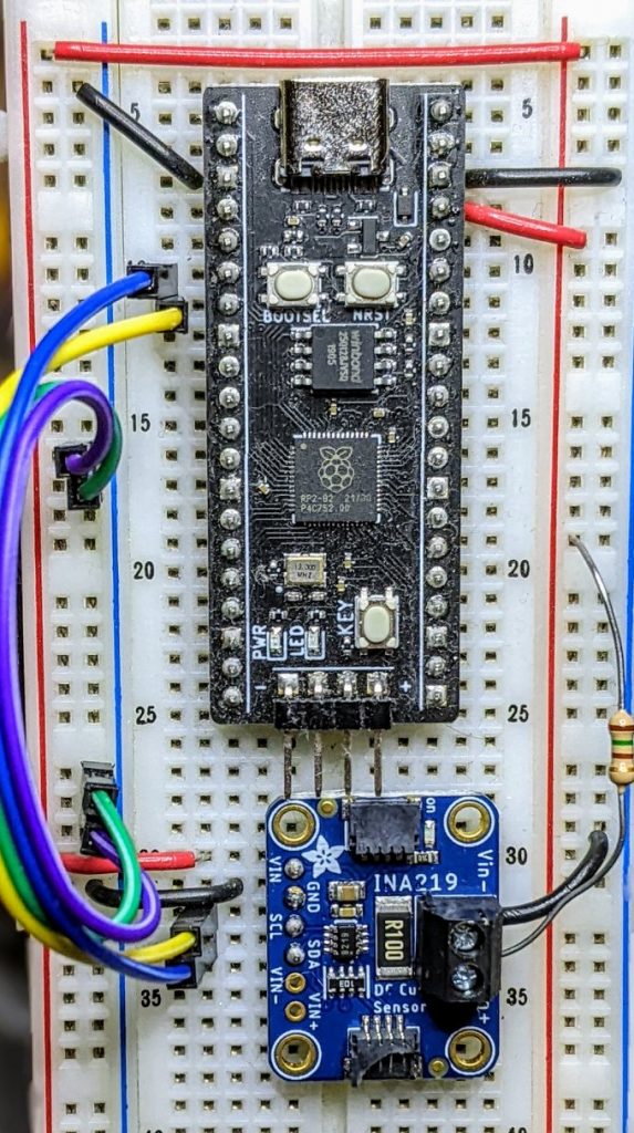
For example, take the INA219 High Side DC Current Sensor. It’s an I²C sensor able to measure up to 26 V, ±3.2 A. It does this by measuring the voltage across a 0.1 ohm precision shunt resistor with its built-in 12-bit ADC. I got a customer return from the store that was cosmetically damaged but still usable, so I thought I’d try it with the simplest module I could find in Awesome MicroPython and see how well it worked.
I guess I needed a test circuit too. Using all of what was immediately handy — a resistor I found on the bench and measured at 150.2 ohm — I came up with this barely useful circuit:
Should indicate a current of 3.3 / (150.2 + 0.1) = 21.96 mA
The INA219 would be happier with a much higher current to measure, but I didn’t have anything handy that could do that.
Looking in Awesome MicroPython’s Current section, I found robert-hh/INA219: INA219 Micropython driver. It doesn’t have much (okay, any) documentation, but it’s a very small module and the code is easy enough to follow. I put the ina219.py module file into the /lib folder of a WeAct Studio RP2040 board, and wrote the following code:
# INA219 demo - uses https://github.com/robert-hh/INA219

from machine import Pin, I2C
import ina219

i = I2C(0, scl=Pin(5), sda=Pin(4))
print("I2C Bus Scan: ", i.scan(), "\n")

sensor = ina219.INA219(i)
sensor.set_calibration_16V_400mA()

# my test circuit is 3V3 supply through 150.2 ohm resistor
r_1 = 150.2
r_s = 0.1  # shunt resistor on INA219 board

# current is returned in milliamps
print("Current       / mA: %8.3f" % (sensor.current))
# shunt_voltage is returned in volts
print("Shunt voltage / mV: %8.3f" % (sensor.shunt_voltage * 1000))
# estimate supply voltage from known resistance * sensed current
print("3V3 (sensed)  / mV: %8.3f" % ((r_1 + r_s) * sensor.current))
with everything wired up like this (Blue = SDA, Yellow = SCL):
all of the wires
Running it produced this:
I2C Bus Scan:  [64]

Current       / mA:   22.100
Shunt voltage / mV:    2.210
3V3 (sensed)  / mV: 3321.630
So it’s showing just over 22 mA: pretty close to what I calculated!
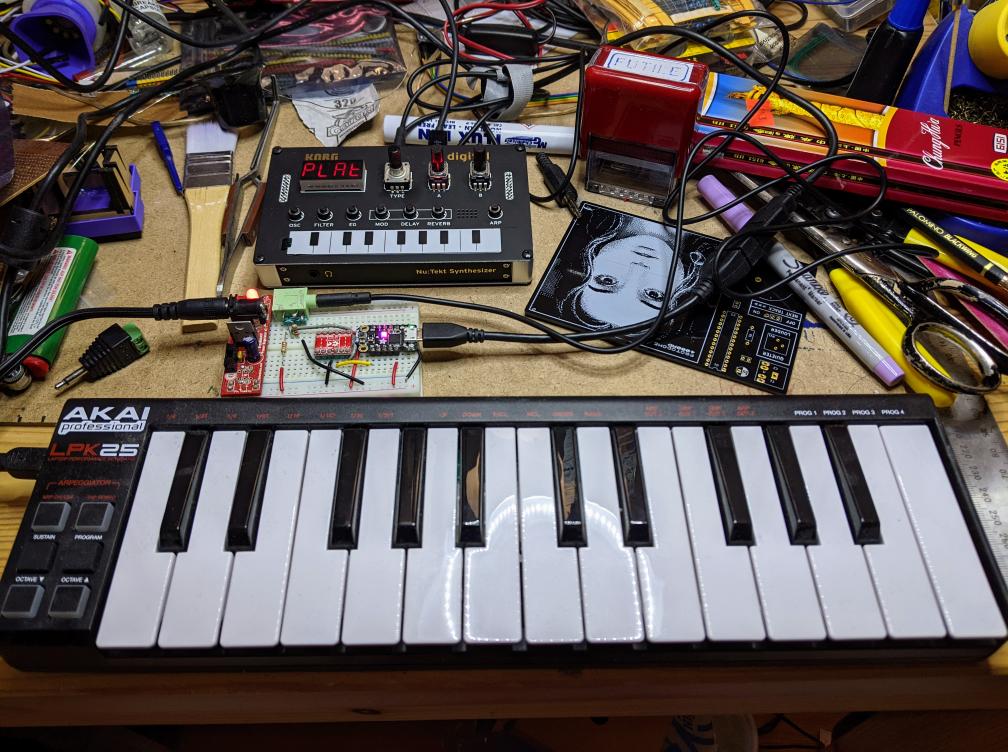
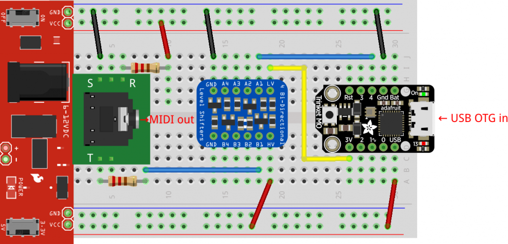
Akai LPK25 keyboard has USB MIDI out, but the Korg NTS-1 only has regular MIDI in. The little board in the middle acts as a USB host for the Akai and MIDI source for the Korg
“Just a test call. Time to stay home. Stay safe and stay home.”
This message from an unknown caller has sat on our landline answering machine since 2020 or 2021. No idea who or what sent it. All I know is it came in just before noon on a Tuesday morning. The entirely synthesized voice makes me think it’s a junk call, but there’s no scam attached. Just this message, slightly eerie, quite inexplicable.
In early 2013, I must’ve been left unsupervised for too long since I made The Quite Rubbish Clock:
It still isn’t human readable …
Written in (Owen Wilson voice) kind of an obsolete vernacular and running on hardware that’s now best described as “quaint”, it was still absurdly popular at the time. Raspberry Pis were still pretty new, and people were looking for different things to do with them.
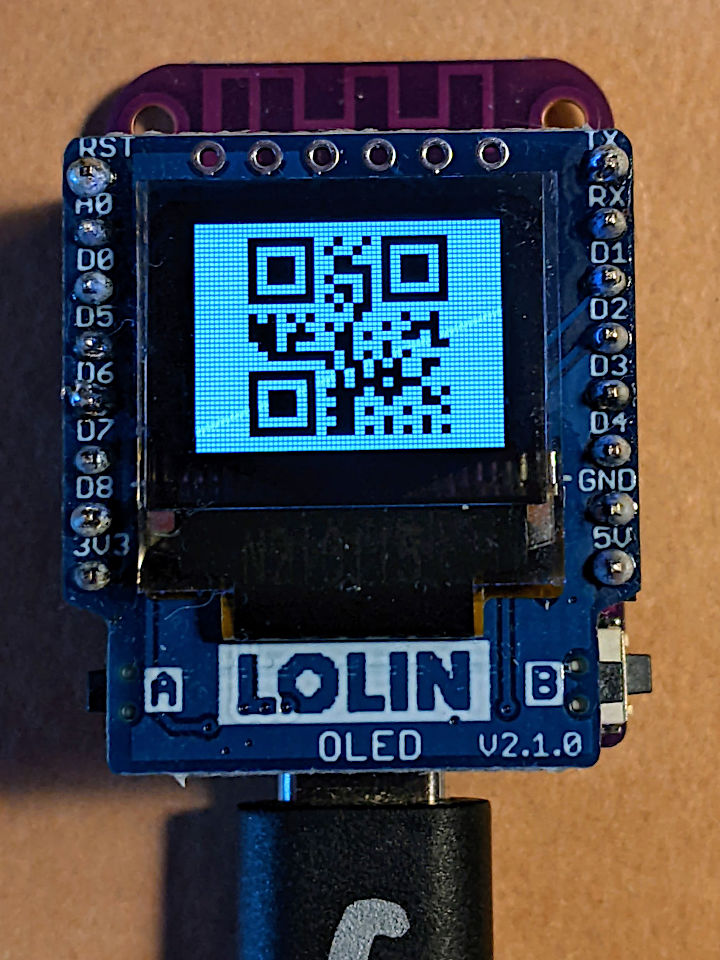
I happened across the JASchilz/uQR: QR Code Generator for MicroPython the other day, and remembered I had some tiny OLED screens that were about the same resolution as the old Nokia I’d used in 2013. I wondered: could I …?
OLED Shield on a LOLIN S2 Mini: very smol indeed
The board is a LOLIN S2 Mini with a OLED 0.66 Inch Shield on top, all running MicroPython. One limitation I found in the MicroPython QR library was that it was very picky about input formats, so it only displays the time as HHMMSS with no separators.
Source, of course:
# -*- coding: utf-8 -*-
# yes, the Quite Rubbish Clock rides again ...
# scruss, 2022-06-30
# MicroPython on Lolin S2 Mini with 64 x 48 OLED display
# uses uQR from https://github.com/JASchilz/uQR
# - which has problems detecting times with colons

from machine import Pin, I2C, RTC
import s2mini  # on Lolin ESP32-S2 Mini
import ssd1306
from uQR import QRCode

WIDTH = 64  # screen size
HEIGHT = 48
SIZE = 8  # text size
r = RTC()

# set up and clear screen
i2c = I2C(0, scl=Pin(s2mini.I2C_SCL), sda=Pin(s2mini.I2C_SDA))
oled = ssd1306.SSD1306_I2C(WIDTH, HEIGHT, i2c)
oled.fill(0)


def snazz():
    marquee = [
        "   **",
        "   **",
        "   **",
        "   **",
        "   **",
        "********",
        " ******",
        "  ****",
        "   **",
        " quite",
        "rubbish",
        " clock",
        "  mk.2",
        "<scruss>",
        " >2022<"
    ]
    for s in marquee:
        oled.scroll(0, -SIZE)  # scroll up one text line
        oled.fill_rect(0, HEIGHT-SIZE, WIDTH,
                       SIZE, 0)  # blank last line
        oled.text("%-8s" % s, 0, HEIGHT-SIZE)  # write text
        oled.show()
        time.sleep(0.25)
    time.sleep(5)
    oled.fill(1)
    oled.show()


snazz()  # tedious crowd-pleasing intro

qr = QRCode()
while True:
    qr.add_data("%02d%02d%02d" % r.datetime()[4:7])
    qr.border = 1  # default border too big to fit small screen
    m = qr.get_matrix()
    oled.fill(1)
    for y in range(len(m)):
        for x in range(len(m[0])):
            # plot a double-sized QR code, centred, inverted
            oled.fill_rect(9 + 2*x, 1 + 2*y, 2, 2, not m[y][x])
    oled.show()
    time.sleep(0.05)
    qr.clear()
If your output is glitchy, you might need to put the following in boot.py:
import machine
machine.freq(240000000)
This increases the ESP32-S2’s frequency from 160 to 240 MHz.
Update: there’s a fork of uQR that provides better character support, particularly those required for sending Wi-Fi Network config.
recreated from the Threlkeld Granite Co Ltd’s Album: Ornamental Granitic Tiles (1898), sheet 8
The Internet Archive has Threlkeld Granite Co Ltd’s Album of ornamental granitic tiles online, and I’m really digging the patterns of the hydraulic tiles they made. I’ve recreated some of their patterns in InkScape, and made this small demo by tiling bitmapped renderings.