

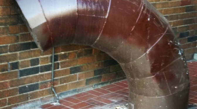
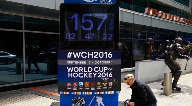
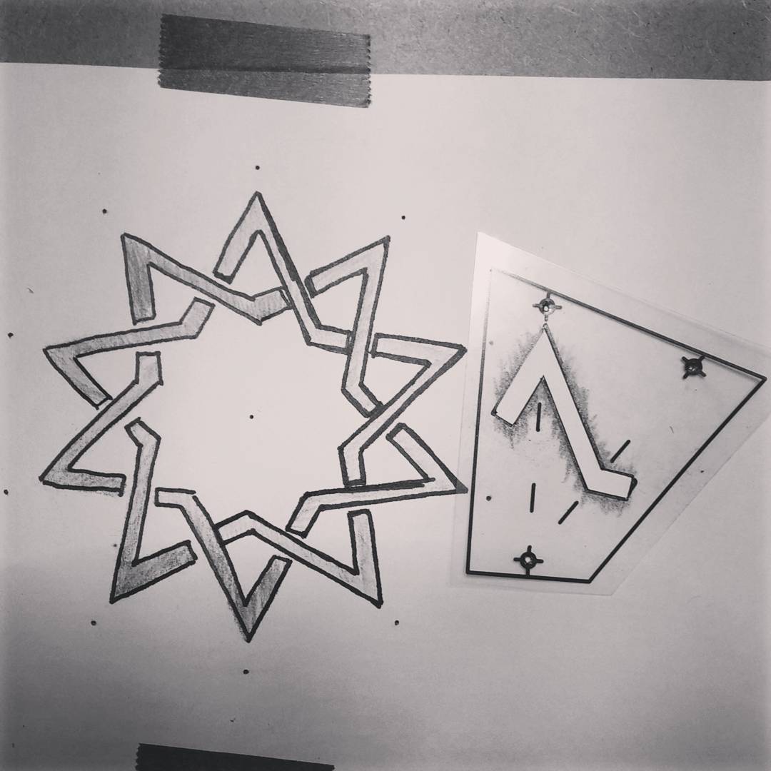
Instagram filter used: Lo-fi
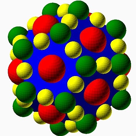
 Nope, no clue. Here’s the source if you want to play with it in a vector drawing program.
Update: I thought I’d work out this audio format some day. I haven’t yet, and since I no longer have the hardware, likely never will.
You may still be able to get Sayso Globord programmable LED signs in surplus stores. It’s a 7×24 LED scrolling sign that you can program with a lightpen or with audio input.
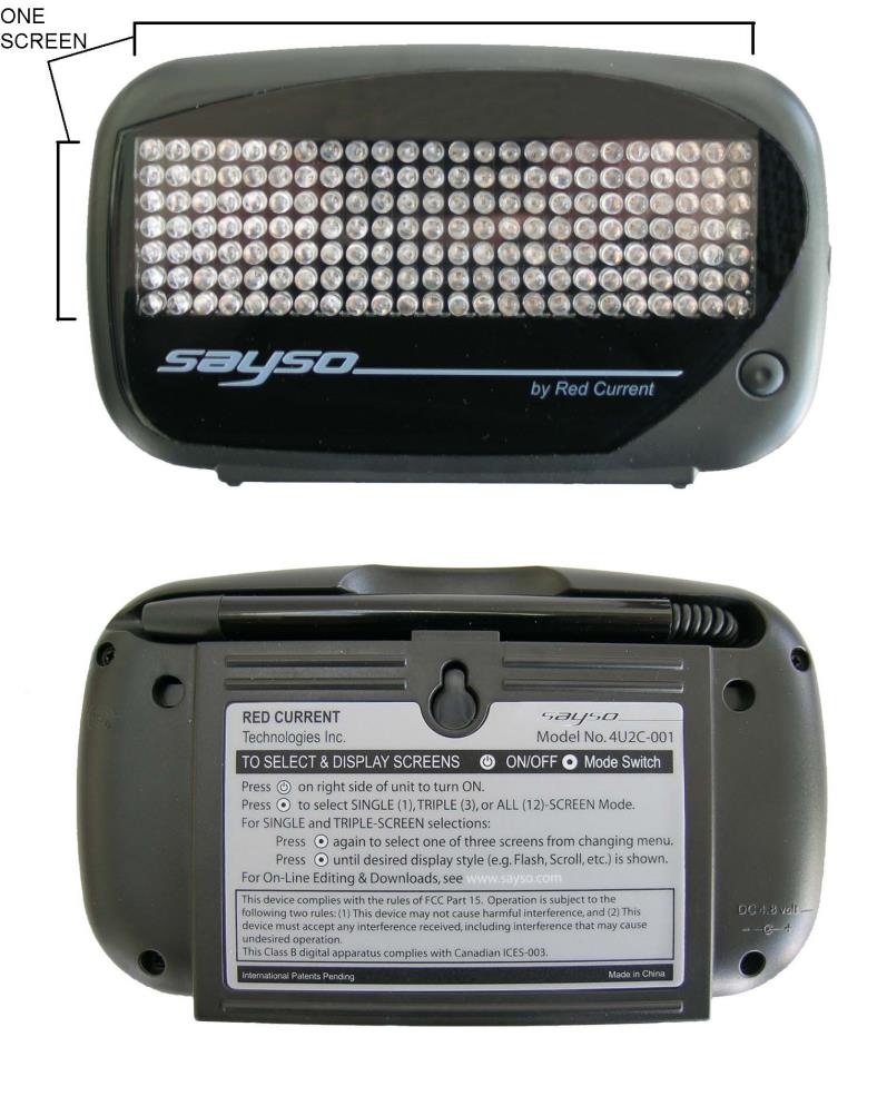
The unit comes with no software, but has a link to https://www.dropbox.com/sh/q1q9yhahwtblb23/AACpMeXQjYyD8ZWC-65vNgcxa printed on the box. (Link is still active in December 2024!). It’s an archive of the programming software, manual, and canned audio files for a whole bunch of standard messages. Here’s an archive if the dropbox link goes away: SaySo.zip
If this page goes away, the software is now on Internet Archive: SAYSO Globord LED Sign archive
The audio files used for programming the display are clearly FSK-encoded, but I haven’t quite worked out the relationship between the tones and the display bits. Here’s what I’ve worked out so far:
The editor runs nicely under DOSBox, so you can experiment and save samples as WAV files. Here’s a sample display with its corresponding audio linked underneath:
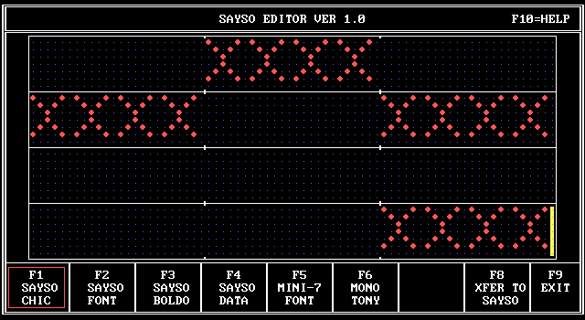
I’m not sure how much extra work I have time or inclination to put in on getting this working, but I hope that my preliminary work will be useful to someone (maybe this person).
Update, 2017-06: I’ve updated the plans so you shouldn’t need to spend time sanding things to fit.
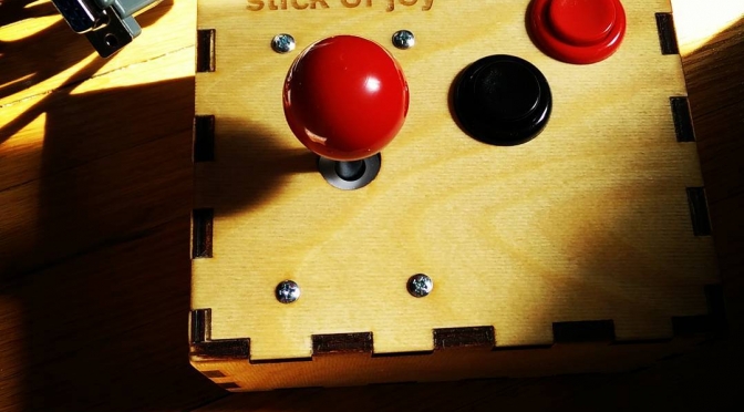
 Tracking down old Atari-style joysticks for retrogaming can expensive, and it’s hard to tell if you’ll get something reliable. So I made one for less than the cost of a used stick on eBay.
To build this, you will need:
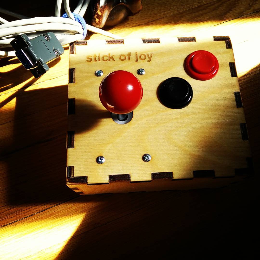
The case is made from 6.4 mm high quality plywood, using a template generated by BoxMaker. The external dimensions of the box are 163 mm x 143 mm x 83 mm. I haven’t included any kerf width in the design, so the edges should fit together easily for gluing.

Joystick box plan for download: joystick-box-201706.svg (SVG: best in Inkscape); joystick-box-201706.pdf (PDF).
If you want to make your own design, here’s the top plate plan: joystick-box-top-201706.svg (SVG); joystick-box-top-201706.pdf (PDF).
The basic DE-9 pin wiring for Atari-style joysticks goes like this:
1 — Up
2 — Down
3 — Left
4 — Right
6 — Button
8 — Ground
There are many variants that add features to this scheme, however. If you’re building for a specific computer, Tomi Engdahl’s Joystick information page has the details.
Many thanks to Andrew Horsburgh for the use of Protolab‘s laser cutter.


