
Instagram filter used: Normal
Hey! I don’t have this meter any more. The scanned manual is all I can help you with (see link near end of article)
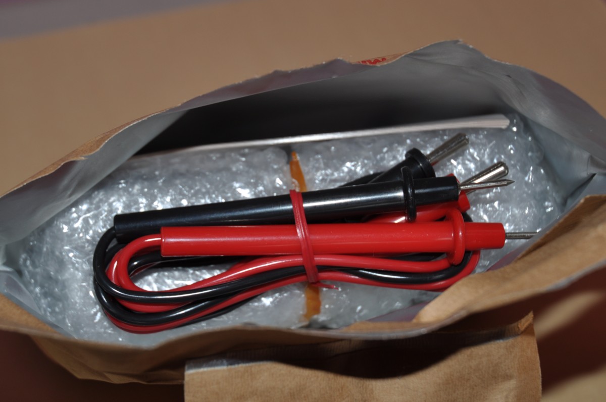
Graham Green had a stall at Make Change yesterday. Graham’s the former manager of Active Surplus, the much-missed Toronto surplus emporium. He had some military-surplus multimeters that hadn’t seen daylight since I was in school. That’s a while back: this (unfortunately) was #1 the week I left school. So I bought one of Graham’s meters just to see what was inside …


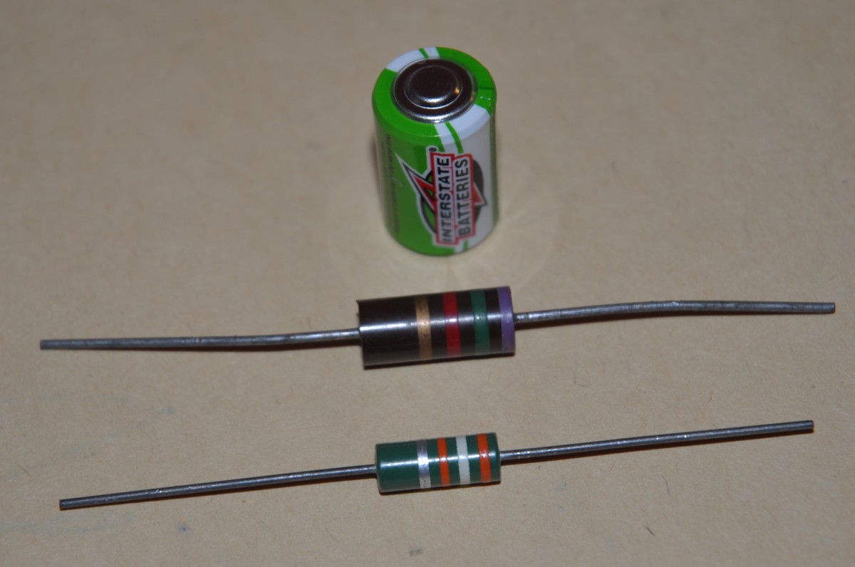


Would I recommend the Soltec as a general purpose meter? Not really. There are more capable multimeters available for about the same price, and you don’t need to go as far as the unbelievably expensive Agilent DMM I use (or even the strictly ornamental analogue ex-Forces Bach-Simpson 635 multimeter that graces/clutters my workbench). It would need a video to show where analogue meters excel: in showing changing values and getting a rough idea of the limits. It would make a great battery tester, or — if coupled with a micro-controller with PWM or DAC ouput — part of a demo rig. If nothing else, it’s a great way to learn how to appreciate modern test gear and all it does for us.
I’m probably going to regret this, but here’s a scan of the Soltec HM-102s manual:


… or what you get if you video concentric RGB LED rings and put them out of focus.

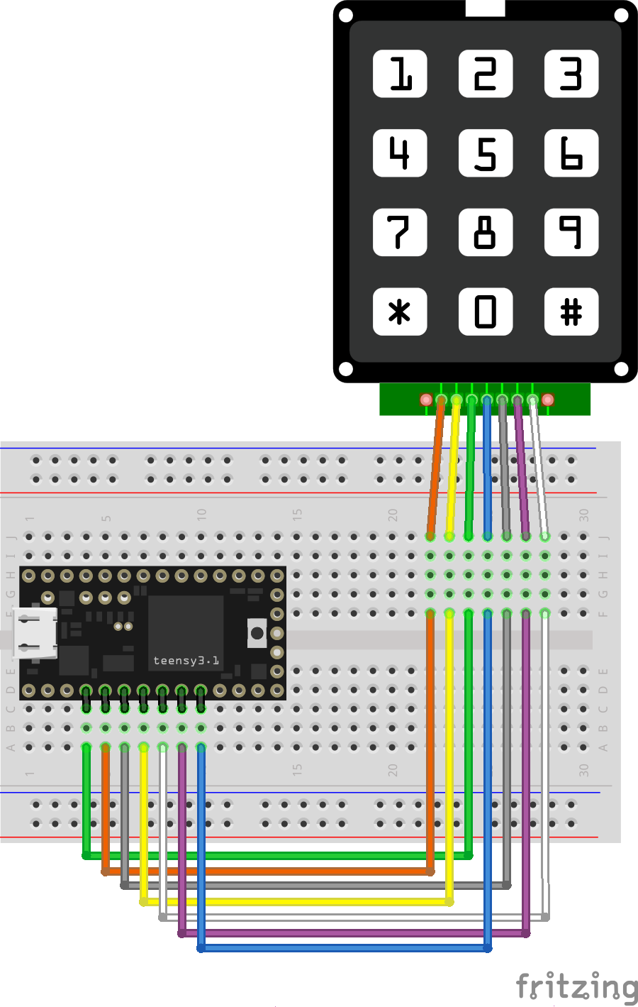
This needs work, but I made this keypad part for Fritzing:
 Part file (zipped): Generic_4x4_Keypad.zip
You’ll see these parts described as variations on “4×4 Matrix 16 Keypad Keyboard Module 16 Button†on ebay. They’re very simple: if you press a button (say S7), the row pins (R1-4; R2 for S7) and the column pins (C1-C4; C3 for S7) are connected. So pins R2 and C3 are connected when S7 is pressed. You can use the Arduino Keypad library to talk to these, but do remember they use up 8 I/O pins.
It’s not internally routed in Fritzing, and you likely won’t be able to use it for any kind of schematic work, but who uses Fritzing for anything other than pretty pictures?
I’ve had a couple of Teensy boards for a while, but a misunderstanding that they needed a load of of extra software installed (they need one thing, and it’s easy) had kept me away. They’ve got really impressive specs, and they’re especially easy to turn into USB devices like keyboards.

Here’s a little demo that turns a phone keypad — in my case, a ridiculously solid CEECO solid metal keypad designed for institutional use — into a simple USB keyboard. Plug it into any machine (including a Raspberry Pi) and it will be identified as a keyboard. No drivers are required.
The code is based on the standard Arduino Keypad library basic demo. That code was meant for a different keypad, so I eventually found a configuration that worked in the Sparkfun 12 button keypad datasheet. Rather than printing characters to the serial port, I used calls to Teensy’s USB Keyboard library instead.
The pinout is (from left to right, key side up):
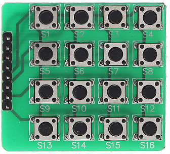
There’s no reason why this wouldn’t work with those very cheap 4×4 button matrix keypads for Arduino too with only minor modifications. Those keypads use 8 data lines, and they’re arranged (I think) as rows 1-4 on pins 1-4 and columns 1-4 are pins 5-8. columns 4-1 then rows 1-4 from the top of the pin connector down:
 The Teensy USB keyboard isn’t limited to sending single characters: a single button press could trigger sending a whole string. I haven’t yet thought out any major uses for this (except “Crypto!â€, which is my usual idea when I have no idea what I’m doing), but you might have better plans.
Update, 2020-04: These keypads don’t have diodes on every key to prevent key ghosting if you press multiple keys. Despite what the Arduino Playground Keypad section might tell you, you can’t do useful multi-key/rollover detection with them.
I’m Scottish. For Hallowen, it’s traditional to make lanterns out of turnips. How this was done before power tools, I’ll never know.
In 2015, I decided to make a traditional neep (that’s Scots for turnip) lantern. Yes, I used a holesaw, and turnip goo went everywhere.

It looked pretty good on the day:

Unlike pumpkins, turnips last. I left it out in the front garden.

It went very wizened:

It disappeared towards the end of May 2016. This was the last time I saw it:

Flushed with success from yesterday’s post where I made my first systemd service, I got carried away and wanted to show you how to create a service that runs as a regular user.
A fairly common question on the Raspberry Pi Forums is “How do I run a script every time I reboot?â€. The traditional answer (and one I’ve given more than once) is to add a @reboot clause to your crontab. This will indeed run a command when the computer reboots, but it will run pretty early on in the boot sequence when there’s no guarantee of network or time services. So the usual remedy is a bit of a kludge:
@reboot sleep 60 && …This waits a full minute after rebooting, then executes the command. Network and time services are really likely to be available, but it’s not very elegant. Cron also has some weird gotchas with PATH settings, so while it’s ubiquitous and has worked for decades, it’s not easy to get working. Systemd, however, has a much better way of doing it, and better yet, you can do it all without ever hitting sudo.
I’ll take as a basis for this post the forum query “python and crontabâ€. The asker wanted to log the time when their Raspberry Pi had rebooted, but they’ve hit the usual problem that the clock didn’t have the right time when their script was triggered, so the log was useless.
(I’m not going to do exactly what the forum poster did, but this is more a demo of a systemd user service than recreating their results.)
First off, here’s the script to log the time to a file (saved as ~/bin/boot_time.py):
#!/usr/bin/python3
from time import strftime
with open("/home/pi/logs/boot_time.txt", "a") as log:
 log.write(strftime("%d-%m-%Y,%H:%M:%S\n"))
I’d have done this as a shell script, but the OP used Python, so why fight it?
FUN FACT: Under most Linux flavours, if you create a bin folder in your home directory, it’s automatically added to your path. So I could just type boot_time.py and the shell would find it.
(You might have to log out and log back in again for the shell to review your path.)
In order to get that to run, I need to do a little housekeeping: make the script executable, and make sure the logs folder exits:
chmod +x ~/bin/boot_time.py
mkdir -p ~/logs
Now we need to do the bits that pertain to systemd. First off, you must make a folder for user services:
mkdir -p ~/.config/systemd/user
NOTE: mkdir -p … is useful here as it makes the directory and any parent directories that don’t exist. It also doesn’t complain if any of them already exist. It’s kind of a “make sure this directory exists†command. Make friends with it.
And here’s the service file, which I saved as ~/.config/systemd/user/boot_time_log.service:
[Unit]
Description=boot time log
DefaultDependencies=no
After=local-fs.target time-sync.target

[Service]
Type=oneshot
ExecStart=/home/pi/bin/boot_time.py

[Install]
WantedBy=default.target
The service file does the following (even if I’m slightly mystified by some of the headings …):
local-fs.target and time-sync.target seem sensible.oneshot rather than the usual simple service.Finally, you enable the service with:
systemctl --user enable boot_time_log.service
Next time you reboot, the time will be appended to the log file ~/logs/boot_time.txt.
Unlike most (that is, Type=simple) services, it’s perfectly fine if this one spends most of its time inactive:
$ systemctl status --user boot_time_log.service â— boot_time_log.service - boot time log Loaded: loaded (/home/pi/.config/systemd/user/boot_time_log.service; enabled; Active: inactive (dead) since Sun 2017-10-22 22:17:56 EDT; 1h 5min ago Process: 722 ExecStart=/home/pi/bin/boot_time.py (code=exited, status=0/SUCCES Main PID: 722 (code=exited, status=0/SUCCESS)
It has executed successfully, so the process doesn’t have to stick around.
Hey! This is obsolete. There are better solutions out there now. You should use the system-supplied and supported gpio-shutdown option instead.
A very simple systemd service for Raspberry Pi that provides a software-controlled restart / shutdown button. Code: scruss/shutdown_button
Default behaviour is:
By default, the software assumes the switch is connected to pin BCM 27. Both the pin and the timing can be changed in the Python source file.

python3-gpiozero package to provide GPIO Zero (tested on version 1.4.0)Connect the button between GPIO 27 and GND. If you use an ATX power button and a Raspberry Pi with a 40-pin GPIO header, connect it across the seventh column from the left:
            -
· · · · · ·|·|· · · · · · · · · · · · ·
· · · · · ·|·|· · · · · · · · · · · · ·
            -
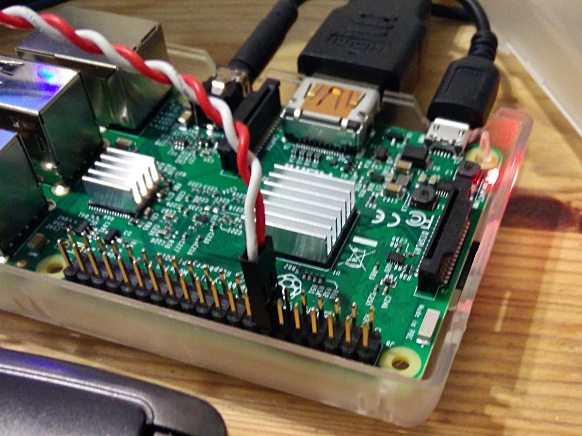
This shorts GPIO 27 (physical pin 13) to ground (physical pin 14) when the button is pressed.
GPIO 27 is not exposed on the original Raspberry Pi header, so GPIO 17 is a reasonable option. If you use an ATX power button and a Raspberry Pi with a 26-pin GPIO header, connect it across the fifth and sixth columns of the second row:
 . . . . ._. . . . . . . .
 . . . .|. .|. . . . . . .
          -
You will also need to change line 7 of shutdown_button.py to read:
use_button=17
Download the software first. I prefer to use
git clone https://github.com/scruss/shutdown_button.git
but you can download the zip file. If you do that, though, make sure to
unzip shutdown_button-master
cd shutdown_button-master
The software is installed with the following commands:
sudo apt install python3-gpiozero
sudo mkdir -p /usr/local/bin
chmod +x shutdown_button.py
sudo cp shutdown_button.py /usr/local/bin
sudo cp shutdown_button.service /etc/systemd/system
sudo systemctl enable shutdown_button.service
sudo systemctl start shutdown_button.service
Enabling the service should produce output very similar to:
Created symlink /etc/systemd/system/multi-user.target.wants/shutdown_button.service → /etc/systemd/system/shutdown_button.service.
You can check the status of the program at any time with the command:
systemctl status shutdown_button.service
This should produce output similar to:
â— shutdown_button.service - GPIO shutdown button
Loaded: loaded (/etc/systemd/system/shutdown_button.service; enabled; vendor
Active: active (running) since Sat 2017-10-21 11:20:56 EDT; 27s ago
Main PID: 3157 (python3)
CGroup: /system.slice/shutdown_button.service
└─3157 /usr/bin/python3 /usr/local/bin/shutdown_button.py
Oct 21 11:20:56 naan systemd[1]: Started GPIO shutdown button.
If you’re seeing anything other than Active: active (running), it’s not working. Does the Python script have the right permissions? Is it in the right place? If you modified the script, did you check it for syntax errors?
The output from dmesg will show you any error messages generated by the service.
If you use a HAT/pHAT/Bonnet/etc. with your Raspberry Pi, check pinout.xyz to see if it uses BCM 27. If you do need to change the pin, best to pick one that doesn’t have a useful system service like serial I/O or SPI. If you’re using an ATX button with a two pin connector, make sure you choose a pin physically adjacent to a ground pin.
If you modify the timing, please ensure that you keep the shutdown button press duration longer than the reboot one. Otherwise you’ll only be able to shut down.
You should not need to reboot to enable the service. One machine of mine — a Raspberry Pi Zero running Raspbian Stretch — did need a reboot before the button worked.
The reboot code is based on the Shutdown button example from the GPIO Zero documentation.
This is not the only combined shutdown/reset button project to use GPIO Zero. gilyes/pi-shutdown also does so, but pre-dates the implementation of the various hold time functions in GPIO Zero.
GPIO 27 was used, as it’s broken out onto a physical button on the Adafruit PiTFT+ display I own.
This is my first systemd service, and I’m still at the “amazed it works at all†stage. The service file may not contain the ideal configuration.
From GPIO Zero’s pinout command
   3V3  (1) (2)  5V
 GPIO2  (3) (4)  5V
 GPIO3  (5) (6)  GND
 GPIO4  (7) (8)  GPIO14
   GND  (9) (10) GPIO15
GPIO17 (11) (12) GPIO18
GPIO27 (13) (14) GND
GPIO22 (15) (16) GPIO23
   3V3 (17) (18) GPIO24
GPIO10 (19) (20) GND
 GPIO9 (21) (22) GPIO25
GPIO11 (23) (24) GPIO8
   GND (25) (26) GPIO7
 GPIO0 (27) (28) GPIO1
 GPIO5 (29) (30) GND
 GPIO6 (31) (32) GPIO12
GPIO13 (33) (34) GND
GPIO19 (35) (36) GPIO16
GPIO26 (37) (38) GPIO20
   GND (39) (40) GPIO21
   3V3  (1) (2)  5V
 GPIO0  (3) (4)  5V
 GPIO1  (5) (6)  GND
 GPIO4  (7) (8)  GPIO14
   GND  (9) (10) GPIO15
GPIO17 (11) (12) GPIO18
GPIO21 (13) (14) GND
GPIO22 (15) (16) GPIO23
   3V3 (17) (18) GPIO24
GPIO10 (19) (20) GND
 GPIO9 (21) (22) GPIO25
GPIO11 (23) (24) GPIO8
   GND (25) (26) GPIO7