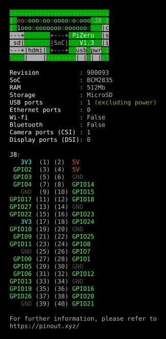
gpiozero (‘A simple interface to GPIO devices with Raspberry Pi’) continues to impress me. One of its newer features is a pinout guide, accessed by the pinout command:
Raspberry Pi Zero pinout – click through for PDF
I’m trying to resist running it on every generation of Raspberry Pi that I have (B, A, 2B, 3B, Zero, Zero W) just for these pretty displays.
(ANSI console colours captured using script, then fed through ansi2html [from the Ubuntu colorized-logs package], printed to PDF from Firefox then mucked about a bit with in Inkscape)
A bit dusty, and no sound, but worked out pretty well. (YouTube link if embed doesn’t work — inky phat draws a design)
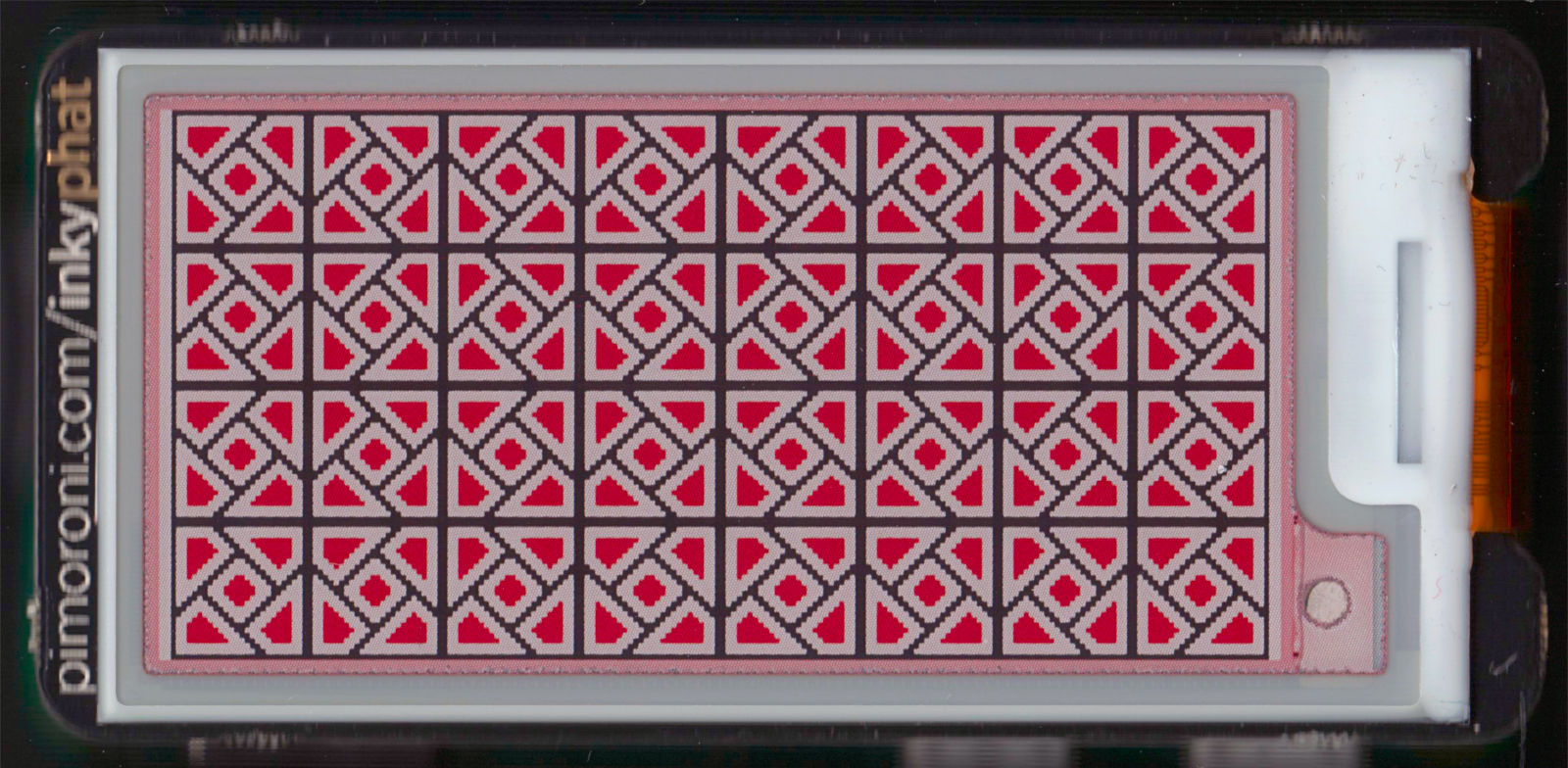
Tiling based on plate 43, “a rotating motif …â€, Wilson, Eva. Islamic designs for artists and craftspeople. New York: Dover Publications, 1988. ISBN: 978-0-486-25819-5
rotating tile pattern on Pimoroni Inky pHAT EPD display
This is a 600 dpi scan of a Pimoroni Inky pHAT EPD display. EPDs — electrophoretic displays, aka ‘e-ink’ or ‘e-paper’ — retain their image when turned off, so this Raspberry Pi had no power when I scanned it.
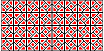
The image I made to fit the display is really small —
It’s a bit of a process making the images with just the right palette in GIMP, but I’m pleased how it turned out. I’d like to be able to write the vector images directly to the screen from SVG, but that might take some time.
Tiling based on plate 43, “a rotating motif …â€, Wilson, Eva. Islamic designs for artists and craftspeople. New York: Dover Publications, 1988. ISBN: 978-0-486-25819-5
I just picked up a micro:bit, the little educational microprocessor board originally from the BBC. It’s a nice little unit, though like all educational resources, it’s sometimes hard to access resources as a non-edu type.
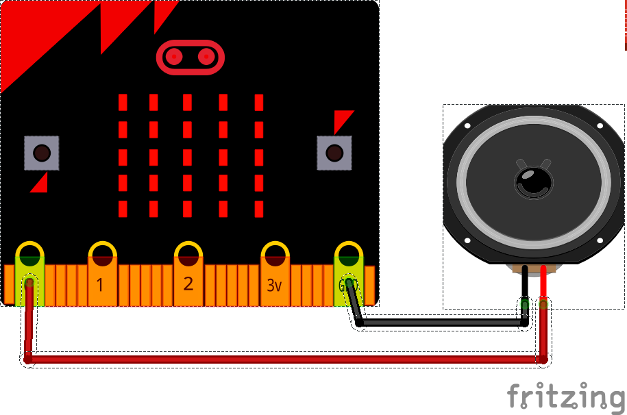
I landed upon MicroPython, a Python language subset that runs directly on the micro:bit’s ARM chip. I rather like the Mu editor: To give the old microcontroller grumps something real to complain about, MicroPython includes a bunch of very high-level functions, such as a powerful music and sound module. Getting the sound out is easy: just croc-clip a speaker onto the output pads:
(MicroPython warns against using a piezo buzzer as a speaker, but mine worked fine — loudly and supremely annoyingly — with a large piezo element. Some piezos have a fixed-frequency oscillator attached, but this simple one was great.)
This trivial example plays the Nyan Cat theme forever, but every time it loops it gets faster. The beats variable starts at the default 120 bpm, but is increased by one every time:
# nyan but it gets faster
import music
beats = 120
while True:
    music.set_tempo(bpm=beats)
    music.play(music.NYAN)
    beats = beats + 1
This starts out as merely irritating, but quite quickly becomes deeply annoying, and in mere hours become vastly vexing. I’m sure you’d only use this power for good …
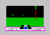
I gave a talk about retro-gaming on the Raspberry Pi yesterday. I was describing RetroPie, and I really needed lots of screenshots to illustrate games. I’m used to grabbing screens under X, but RetroPie runs without it, so all my usual tools were of no use.
I’d just found out about raspi2png, and it works really well! Usage is simple: just call it like
raspi2png -p outfile.png
and it’ll save whatever’s on the screen. It doesn’t play well with X, but there are already tools to take screenshots with that. As I was playing games, I didn’t want to have to pause the computer to take a shot, so I ran the command every five seconds for 30*5 seconds like this:
for f in {1..30}; do raspi2png -p retro_$(date -Iseconds).png; sleep 5; done
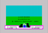
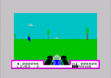
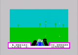
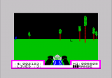
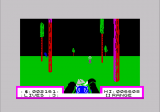
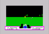
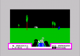
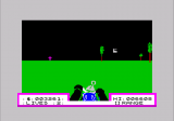
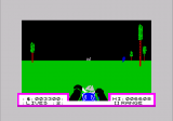
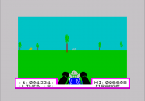
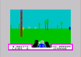
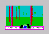
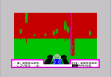
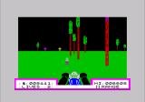
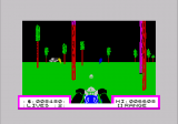
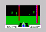
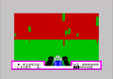
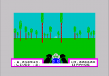
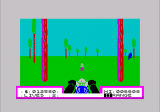
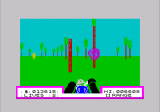
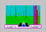
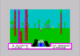
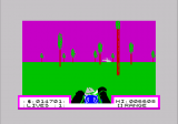
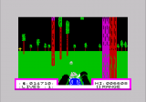
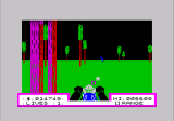
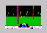
Here are some quality shots via raspi2png from Deathchase, officially the best ZX Spectrum game ever:
The best words ever to appear on a computer screen
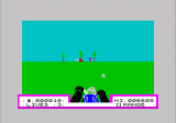
Baddies off in the distance
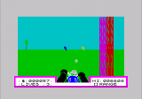
I appear to be shooting small jellyfish, or lumps of ice cream
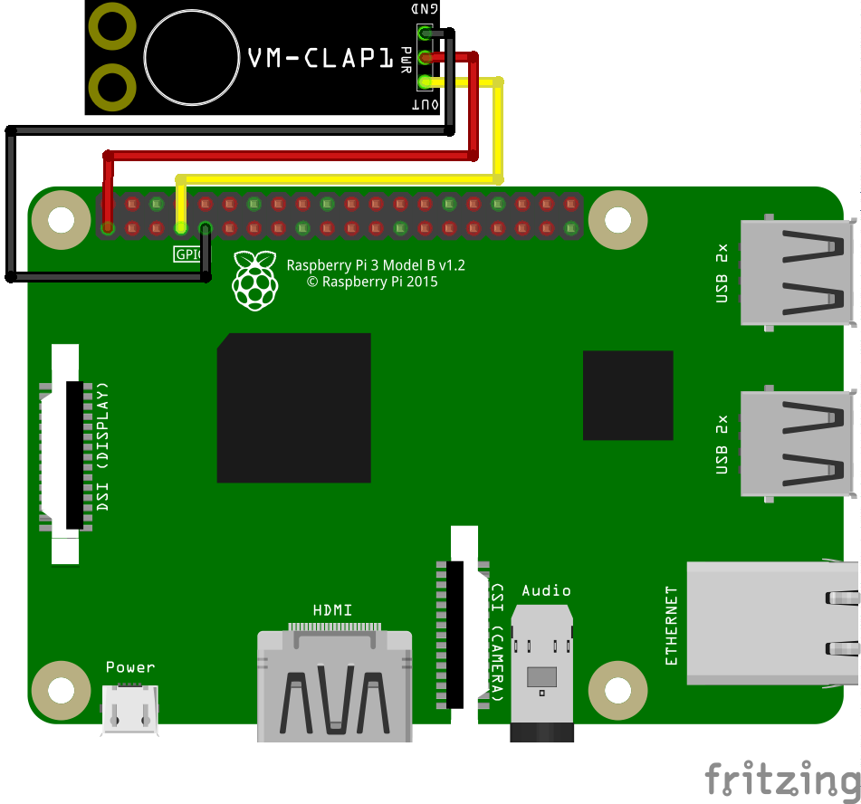
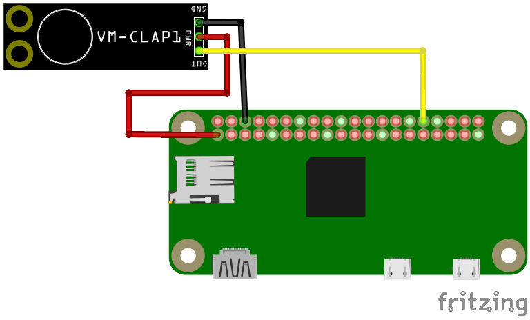
Since the Verbal Machines VM-CLAP1 sensor is an open collector type — that is, it sinks current when triggered — it behaves like a simple button to gpiozero, the Raspberry Pi Python GPIO library. If you attach a callback function to the sensor’s when_pressed event, your Python script will call that function every time it registers a clap.
The wiring is as simple as it could be:
 VM-CLAP1: Raspberry Pi:
 ========= =============
      GND → GND
      PWR → 3V3
      OUT → GPIO 4
This example code just prints clap! when the board picks up a ðŸ‘:
#!/usr/bin/env python3
# -*- coding: utf-8 -*-

# Raspberry Pi gpiozero test for
# Verbal Machines VM-CLAP1 clap sensor
#   scruss - 2017-06
#
# Wiring:
#
#  VM-CLAP1:    Raspberry Pi:
#  =========    =============
#    GND     →   GND
#    PWR     →   3V3
#    OUT     →   GPIO 4

from gpiozero import Button
from signal import pause

def clapping():
        print("clap!")

clap = Button(4)
clap.when_pressed = clapping
pause()
This is a trivial example, but at least it shows that anything you can do with a button, you can also do with this hand-clap sensor.
It should work in Breadboard and Schematic mode, but absolutely doesn’t work in PCB mode. This shouldn’t be a problem, as it’s only available as a standalone board. Fritzing doesn’t have any way to create new parts from scratch any more, so I had to base it on a somewhat similar-looking board, the SparkFun Electret Microphone Breakout.
I’m looking forward to see what I can do with gpiozero and the clap sensor.
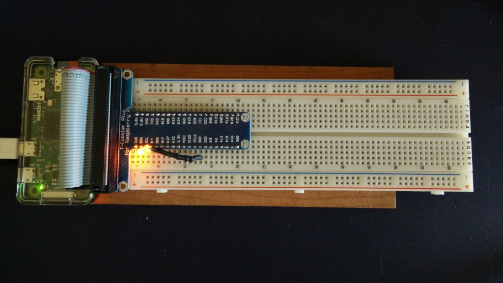
I just set up a Raspberry Pi Zero to be a little breadboard computer. Running a headless machine only through SSH gets a bit dull at times, so the inclusion of VNC Connect in Raspbian is handy.
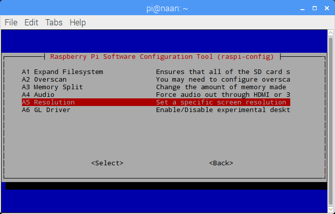
Only problem was that the default screen size — something like 720×480 — was too small for most dialogue windows. Here’s how to enable a more useful resolution of 1024 × 768.
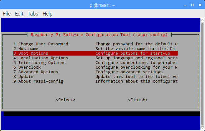
All of these are enabled from the raspi-config tool, so open a terminal and start it with:
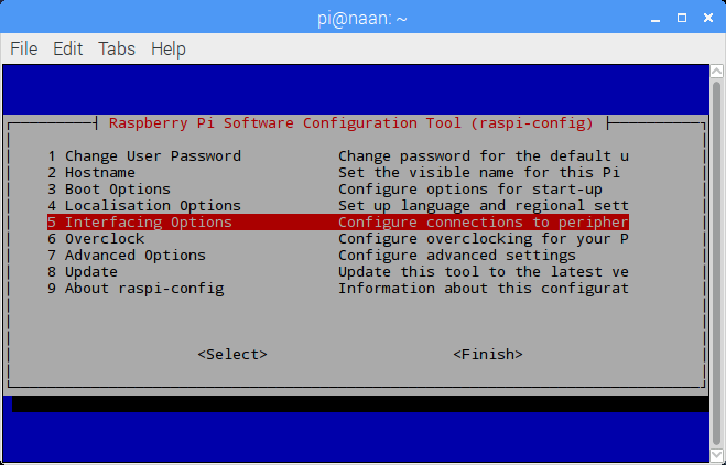
Select 5 Interfacing Options → P3 VNC, and answer Yes to Would you like the VNC Server to be enabled?: Set Screen Resolution
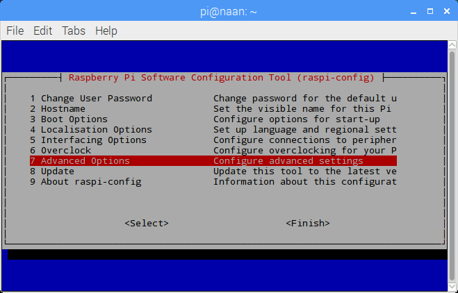
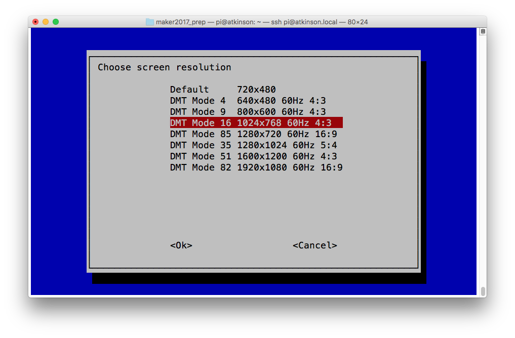
Select 7 Advanced Options → A5 Resolution → DMT Mode 16 (1024×768) …: Once you’ve enabled all of these, raspi-config will ask if you wish to reboot your Raspberry Pi. Once it has rebooted, you should have a usable remote desktop.
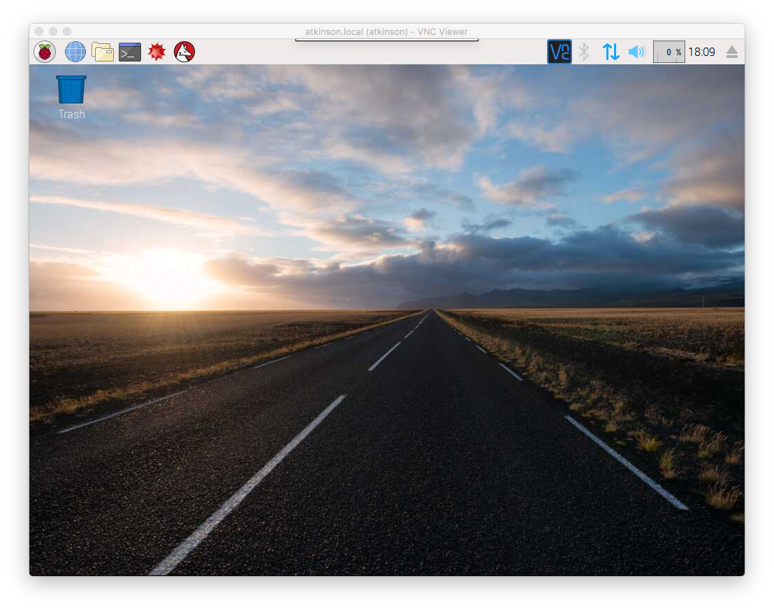
(All of the above screenshots were taken from a headless Raspberry Pi Zero via VNC.)
Before & After
These were taken later on a Raspberry Pi 2 I’m setting up for a maker festival booth:
decidedly smol: 720×480fix it to 1024×768 …so much better!
I don’t know how many times I’ve written bad Arduino code to call a function every few milliseconds. Sometimes this bad code works well enough for my sketch to actually work. Often, it either doesn’t work at all or does something I really didn’t expect.
So on Arduino Day 2017, I’m glad I found out about bhagman/MillisTimer: A Wiring and Arduino library for working with millis(). It couldn’t be simpler to use: include the library, write the function you want to call every N milliseconds, set up the timer to run every N millis, and put timer.run() in a loop that’s called frequently. The library handles the timing and resetting all by itself.
As an example, here’s the eternal “Hello, World!†of the embedded world, Blink, rewritten to use MillisTimer:
// MillisTimerBlink - blink LED every second
//  using Brett Hagman's MillisTimer library
//  https://github.com/bhagman/MillisTimer
//  (or use Sketch → Include Library → Manage Libraries … to install)
// scruss - 2017-04-01

#include <MillisTimer.h>
MillisTimer timer1;               // new empty timer object
const int led_pin = LED_BUILTIN;  // use the built-in LED

void flash() {                    // function called by timer
  static boolean output = HIGH;
  digitalWrite(led_pin, output);  // set LED on or off
  output = !output;               // toggle variable state High/Low
}

void setup() {
  pinMode(led_pin, OUTPUT);       // use built-in LED for output
  timer1.setInterval(1000);       // set timer to trigger every 1000 millis
  timer1.expiredHandler(flash);   // call flash() function when timer runs out
  timer1.setRepeats(0);           // repeat forever if set to 0
  timer1.start();                 // start the timer when the sketch starts
}

void loop() {
  timer1.run();                   // trigger the timer only if it has run out
  // note that run() has to be called more frequently than the timer interval
  //  or timings will not be accurate
}
Note that MillisTimer only triggers when timer.run() is called. Sticking a delay(2000) in the main loop will cause it to fire far less frequently than the interval you set. So it’s not technically a true periodic timer, but is good enough for most of my purposes. If you want a true interrupt-driven timer, use the MsTimer2 library. It relies on the timer interrupts built into the Arduino hardware, and isn’t quite as easy to use as MillisTimer.
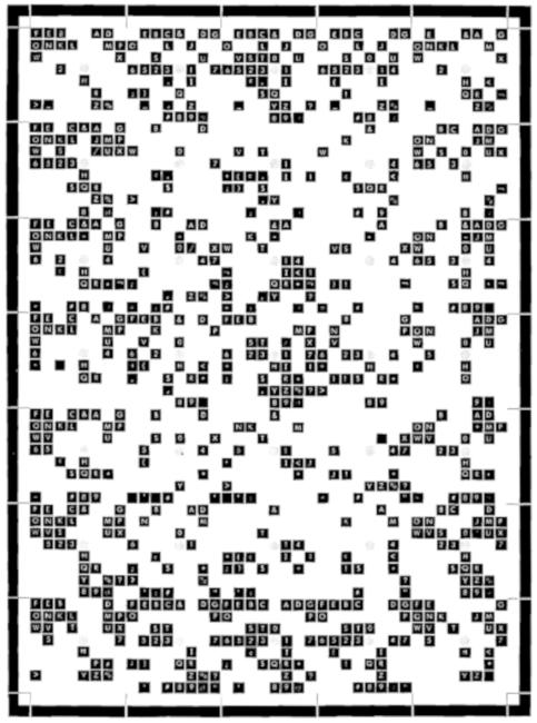
The 029 (as it is sometimes known) generated a bitmap font from an engraved metal plate pressing on a matrix of pins. A picture of this plate from a field engineering manual was used to re-create the pin matrices, and thus an outline font.
029 Code Plate029 Code Key
Historical Accuracy
The 029 could have many different code plates, but the one used here contained the characters:
The character glyphs have been sized such that if printed at 12 points, the 029’s character pitch of 0.087″ is accurately reproduced. No attempt to research the pin matrix pitch or pin diameter has been made: the spacing was eyeballed from a couple of punched cards in my collection.
The earlier IBM Type 26 Card Punch (“026”) included a glyph for a square lozenge (Unicode U+2311, ⌑). The 029 code plate did not include this character, but I added it here for completeness.
The character set was extended to include:
all of ASCII, with lower case characters repeating the upper case glyphs;
sterling currency symbol; and
euro currency symbol.
While there may have been official IBM renditions of some of these additional glyphs (with the exception of euro) no attempt has been made to research the original shapes. This font set is intended to help with the visually accurate reproduction of 1960s-era punched cards, mostly coinciding with my interest in the FORTRAN programming language. No attempt has been made to use historical BCD/EBCDIC encodings in these fonts. We have Unicode now.
The 029 card punch could not produce any bold or italic font variants, but FontForge can, so I did.
Things I learned in making these fonts
The 029 card punch printer could be damaged if you tried to print binary cards, as there was no way to disengage the code plate from the punch mechanism.
FontForge really hates to have paths in a glyph just touching. Either keep them more than one unit apart, or overlap them and merge the overlapping paths.
EBCDIC is weird.
Sources
Norbert Landsteiner’s amazing Punched Card Typography Explained page describes how the code plate system worked, and has JavaScript animations showing how characters were decoded (entirely mechanically) from the plate.
Of all the niche blog entries I’ve written, this must be the nichest. I don’t even like the topic I’m writing about. But I’ve worked it out, and there seems to be a shortage of documented solutions.
UTF-16 grew out of an early standard, UCS-2, that was all like “Hey, there will never be a Unicode code point above 65536, so we can hard code the characters in two bytes … oh shiiii…â€. So not merely does it have to escape emoji code points down to two bytes using a very dank scheme indeed, it then has to further escape everything to ASCII. That’s how your single emoji becomes 17 bytes in an RTF document.
So here’s a tiny subroutine to do the conversion. I wrote it in Perl, but it doesn’t do anything Perl-specific:
#!/usr/bin/env -S perl -CAS
# emoji2rtf - 2017 - scruss
# See UTF-16 decoder for the dank details
#  <https://en.wikipedia.org/wiki/UTF-16>
# run with 'perl -CAS ...' or set PERL_UNICODE to 'AS' for UTF-8 argv
# doesn't work from Windows cmd prompt because Windows ¯\_(ツ)_/¯
# https://scruss.com/blog/2017/03/12/in-the-unlikely-event-you-need-to-represent-emoji-in-rtf-using-perl/

use v5.20;
use strict;
use warnings qw( FATAL utf8 );
use utf8;
use open qw( :encoding(UTF-8) :std );
sub emoji2rtf($);

my $c = substr( $ARGV[0], 0, 1 );
say join( "\t⇒ ", $c, sprintf( "U+%X", ord($c) ), emoji2rtf($c) );
exit;

sub emoji2rtf($) {
    my $n = ord( substr( shift, 0, 1 ) );
    die "emoji2rtf: code must be >= 65536\n" if ( $n < 0x10000 );
    return sprintf( "\\u%d?\\u%d?",
        0xd800 + ( ( $n - 0x10000 ) & 0xffc00 ) / 0x400 - 0x10000,
        0xdC00 + ( ( $n - 0x10000 ) & 0x3ff ) - 0x10000 );
}
This will take any emoji fed to it as a command line argument and spits out the RTF code:
Just to show that this encoding scheme really is correct, I made a tiny test RTF file unicode-emoji.rtf that looked like this in Google Docs on my desktop:
It looks a bit better on my phone, but there are still a couple of glyphs that won’t render:
Update, 2020-07: something has changed in the Unicode handling, so I’ve modified the code to expect arguments and stdio in UTF-8. Thanks to Piyush Jain for noticing this little piece of bitrot.
Further update: Windows command prompt does bad things to arguments in Unicode, so this script won’t work. Strawberry Perl gives me:
perl -CAS .\emoji2rtf.pl ☺
emoji2rtf: code must be >= 65536; saw 63
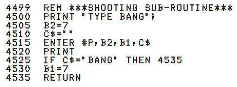
 DI 30
 XC 45
 XC 205
…
 IF 700
 NM 730
… (many, many more lines …)
I thought at first it was a stack trace, but nope — it’s error messages! You need to dig through your trusty language manual, and on page 132 it has a table to explain:
DI ERROR IN DIM STATEMENT
IF ERROR IN IF STATEMENT
NM MISSING LINE NUMBER
XC CHARS AFTER END OF LINE
(and yes, they’re in all-caps. Mixed case? Mixed feelings!)
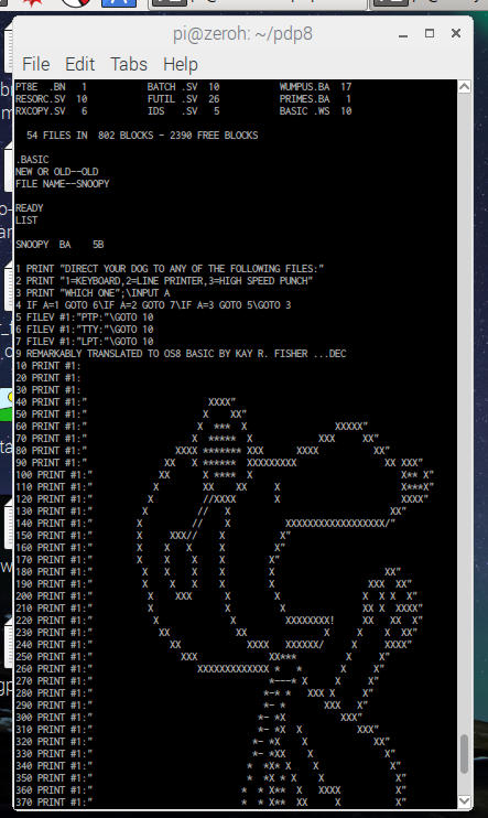
So whenever Python throws a tantrum (or as it calls it, an exception) and wails at length about its problems, remember PDP-8 BASIC: Two letters + a line number. That’s all.
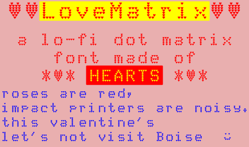
Full Language Support: Afrikaans, Baltic, Basic Latin, Catalan, Central European, Dutch, Esperanto, Euro, Turkish, Western European. Terrible kerning comes free.
PDP (Pocket DEC Pretender) Zero: lettering came out a bit more, um, artisanal than I’d hoped …
Digital (aka DEC) used to make some very solid minicomputers back when a minicomputer was fridge-sized and people were still building nuclear power stations to be controlled by them. The Raspberry Pi Zero is a very mini computer indeed, and in USB gadget mode running SimH it makes a nice little emulation platform.
DEC minis were famous for their arrays of blinkenlights. The Pocket DEC Pretender, not so much: it has one tiny green light that flickers a bit now and again:
PDP (Pocket DEC Pretender) Zero: case open, very few blinkenlights
But it’s a genuinely useful (for my values of useful) emulation platform. Here it is pretending to be a PDP-8, running BASIC under OS-8:
PDP (Pocket DEC Pretender) Zero: PDP-8 BASIC!
(background in case pictures woven in Toronto by Deftly Weft)
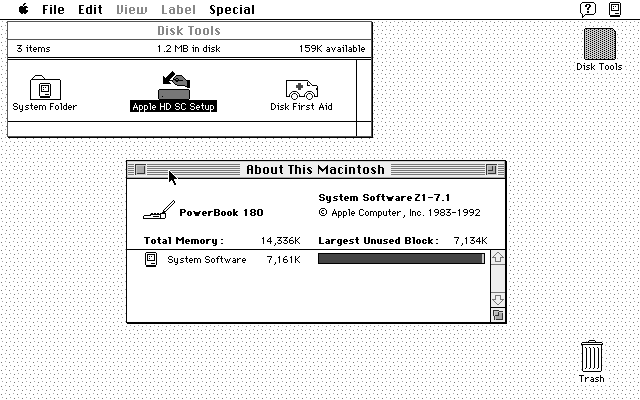
Seems I have two Macintosh PowerBook 180s: one has a dead colour screen but seems to boot fine, and the other (the one screenshotted above; yay ⌘+Shift+3 and enough room on the boot floppy …) has a lovely greyscale screen but a dead hard drive. I suspect we’re going to have to do a head transplant.
And no, I’m not having ¼-century 68030+68882 wish fulfillment one bit …
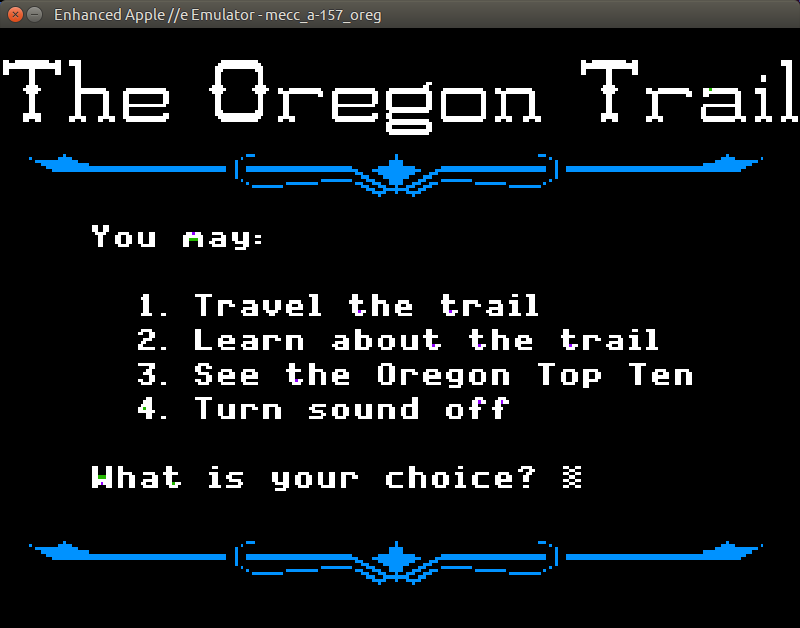
Building and installing the linapple-pie Apple IIe emulator is relatively easy on the Raspberry Pi:
sudo apt install libcurl4-openssl-dev libzip-dev zlib1g-dev libsdl1.2-dev libsdl-gfx1.2-dev libsdl-image1.2-dev libsdl-sound1.2-dev build-essential git
git clone https://github.com/dabonetn/linapple-pie.git
cd linapple-pie/src
make
sudo make install
This also works on an x86_64 Ubuntu machine. It does also install on a PocketCHIP (even if it takes a really long time) but I can’t get the display resolution to fit correctly.
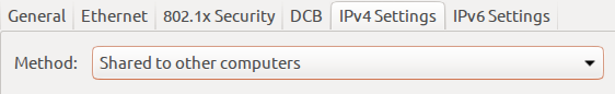
The Raspberry Pi Zero can be set up to appear as one of several USB OTG “gadgets†if you plug it into another computer. The most popular setting seems to be the virtual network gadget that turns your Zero into a computer on the end of your USB cable. Andrew Mulholland’s guide Raspberry Pi Zero – Programming over USB! (Part 2) (along with his super-short simple guide) seems to be the definitive source on how to set these modes up.
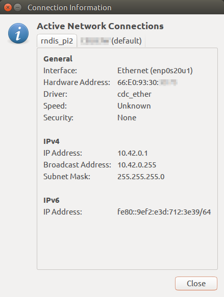
One problem, though, is that the Zero would show up on different network addresses every time it was restarted. The changing addresses made ssh access no fun at all. A suggestion on the Raspberry Pi forum helped me come up with a solution. On the Raspberry Pi Zero, run this command once:
This will set the USB port’s hardware addresses to a fixed value, and you should always get a connection on the same IP address if it’s available.
How my Raspberry Pi Zero appears on my Ubuntu machine
Update: For some reason, this seemed to stop working, and I was getting the old random addresses again. I was resisting putting more stuff in /boot/cmdline.txt, but it seems to me it’s more reliable than what I proposed. So if your g_ether.conf looked like: