Josh Bensadon had brought some very silly little devices he’d made that played the startup chime when you pressed a button. They contained a small PIC chip programmed with the PWM sequence, a tiny speaker, a battery and the switch. For certain people, it brought so much joy. Retrocomputing folks can be easily amused, it seems.
I don’t have a PET, but I do have fond memories of the one we borrowed from school during the holidays around 1980. The PET doesn’t have great sound capabilities, as Dave at Tynemouth Software notes. But looking at the captured waveform dumped from VICE’s audio output, it looks suspiciously close to four repeats of these 7 steps:
80 cycles of 4329.0 Hz;
40 cycles of 2164.5 Hz;
20 cycles of 1082.3 Hz;
10 cycles of 541.1 Hz;
20 cycles of 1082.3 Hz;
40 cycles of 2164.5 Hz;
80 cycles of 4329.0 Hz.
Conveniently, all of these steps have the same duration (0.01848 s). The odd series of frequencies seem to be coming from a clock divider: 4329.0 Hz is 1,000,000 ÷ 231, 2164.5 Hz is 1,000,000 ÷ (2 × 231), and so on.
The end result, cobbled together by many calls to sox, sounds like this:
Commodore PET Synthesized Startup Chime: mp3
It sounds not too bad. It doesn’t have the fade-in effect caused by the PET’s power supply coming on, but it has the right character.
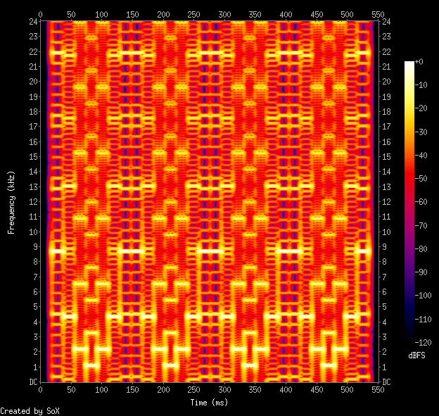
Its spectrogram is particularly special:
Commodore PET Synthesized Startup Chime: spectrogram. Yes, it’s all square waves
E. Lamprecht’s MZ2SYNTH is a delightfully weird piece of code. It is an advanced wavetable synthesizer programmed only by an input image. Here’s an example:
Documentation is pretty sparse, so I’ve had to work it out as best I can:
input data must be a 720 px high NetPBM PPM or PGM image with a black background
waveforms are specified by pixel colour: sine, square, sawtooth and triangle are red, green, blue and luminance
dynamics are manipulated by changing the pixel brightness
the input plays at a constant rate along the horizontal pixels, defaulting to 10 pixels/second
The pitch is specified by the Y coordinate. To convert from MIDI note number n to an input coordinate for mz2synth, use this formula: y=6×(140 – n) So for Middle C (MIDI note 60), the Y coordinate would be 480.
I’ve created a very simple example that plays a C major scale with simple sine waves with no dynamics.
The input image:
The resulting audio:
And the python code that produced the image:
#!/usr/bin/env python3
# -*- coding: utf-8 -*-
# mz2-draw - draw a Cmaj scale in the right input format for mz2synth
# scruss, 2025-11
# mz2synth - https://github.com/frankenbeans/MZ2SYNTH
# command line:
#   mz2 -v -o mz2-cmaj.au mz2-cmaj.ppm

from PIL import Image, ImageDraw


# convert midi note number (20..127) to
# vertical offset for mz2 input
# notes < 20 (G#0) can't be played by mz2
def midi_to_y(n):
    return 6 * (140 - n)


middle_c = 60
maj_scale = (0, 2, 4, 5, 7, 9, 11, 12)
# maj_chord = (0, 4, 7)

# mz2 input must be 720 px high,
# preferably black bg
im = Image.new("RGB", (10 * len(maj_scale), 720), "black")
draw = ImageDraw.Draw(im)

for i, d in enumerate(maj_scale):
    # bright red lines mean full
    # volume sine waves
    draw.line(
        [
            10 * i,
            midi_to_y(middle_c + d),
            10 * i + 8,
            midi_to_y(middle_c + d),
        ],
        "red",
        1,
    )

# mz2 can only read NetPBM PPM format
im.save("mz2-cmaj.ppm")
Building
mz2synth comes with Windows and Mac OS binaries. To run the Mac code, you need Homebrew with the gcc@13 recipe. See this issue for details.
To build on Linux, you’ll need gfortran. A build script could be something like this:
git clone https://github.com/frankenbeans/MZ2SYNTH.git
cd MZ2SYNTH/SOURCE
make -f Makefile.gfortran
Put the resulting mz2 binary somewhere in your path, and that’s all the installation it needs. These same instructions should work for Mac OS.
If you really want to live on the edge (note: not really) and get a faster binary at the expense of array bounds checking, use this to recompile instead of the above make line:
Atari ST disks were weird. Although they were nominally FAT format 3½″ double density disks, they wouldn’t read on a PC. You could format a disk on a PC, however, and the Atari would read/write it just fine.
I had a (virtual) stack of roughly 170 Atari ST disk images that I wanted to access from Linux. mtools, the FAT image reading suite for Linux, could only read 4 of the disks. It didn’t help that some of the images had 82 tracks, or 11 sectors per track, where 80 tracks and 9 sectors per track were standard. I knew that the Hatari emulator could read the images, but the ST’s graphical interface made automation difficult.
I sought help years ago, but that didn’t come to much. I tried again the other day: hatari’s hatari-prg-args combined with the gulam shell made it work.
You’ll probably need EmuTOS so that Hatari can emulate hard drives. I used the current etos512us.img ROM image throughout.
First, I made a folder structure for the emulated hard disk:
If you’re transferring a lot of disk images, you probably want to add some speed-up options to the Hatari command line. For my batch conversion job, I added:
--fast-forward 1 --cpuclock 32 --fast-boot 1 --fastfdc 1 --protect-floppy on
The whole disk contents are now in the gemdos/bclip folder:
This process allowed me to batch-convert most of FaST Club’s Mono Clip Art collection and put it up on the Internet Archive in a readable format: FaST Club Mono Clip Art Selection
Update …
I now have an Atari ST, and something very odd happened: I can read (real) Atari ST disk images just file with mtools. Here’s one to play with:
Tom’s A Short Course In Programming (1980) is a good introduction for new 1802 programmers. Print copies are rare, so someone on the cosmacelf group asked if it existed as a printable PDF. Well, when you put it like that …
conversion shell script, for those who like to tinker and/or want to use a sensible page size: short_course.sh (zipped). It uses curl to download the web pages and Calibre’s ebook-convert to do the HTML → PDF (and e-book) magic.
The linked PDF is quite similar to what you’d get if you went to Tom’s page and selected File → Print… in your browser, except:
the cover image is a Netronics ELF II, from Wikimedia Commons — with the appropriate attribution inserted into the document, as required by the image licence;
a known typo is corrected: references to $2E80 are changed to $2E82;
the document links to Tom’s site.
All of this is done automatically, so if any of the source URLs change, the script will break.
… Other than hats or pins I find there is rarely a good reason for a pi these days. You can get cheap x86 thin clients that beat the pants off them – the dell wyse ones are very cheap on ebay and excellent, the 5070 has an m2 slot and upgradable ram.
I’ve had Raspberry Pis since they were launched. I used to work for an Official Reseller. I’ve been hired for my expertise with them. They’re so much part of the woodwork around here that I’ve never really considered them expensive. So how do they compare to an ex-corporate thin client box?
Dell Wyse 5070
I found one on eBay from a local reseller, GREENSTAR💻⭐. For $68.44 including sales tax (that’s €42), I got a used thin client box including:
a great big power supply brick;
Intel j5005 quad core cpu, fanless;
8 GB of DDR4 RAM (dated 2021);
128 GB SATA M.2 SSD;
3× DisplayPort video ports, 1920×1080 at 60 Hz;
5× USB 3 ports, 1× USB C port and 2× USB 2 ports;
a real 9-pin serial port;
no wifi!
This isn’t a detailed hardware review: for those, I suggest you read Gough Lui and David Parkinson. To get this machine up to a usable spec, I added:
a DisplayPort → HDMI cable (about $20);
a replacement BIOS backup battery ($1);
a cheap USB wifi adapter. I’m still finding old RTL8188CUS dongles about the house from the early Raspberry Pi days, some still in original packaging. These work, but aren’t great, but I can’t beat the price.
All in — excluding monitor, keyboard and mouse — I’ll say I brought it in for $100 inclusive (about €61).
Raspberry Pi 5
To come up with an equivalent system (bought from an Official Reseller that I didn’t work for) I’d need:
Description
Price
Raspberry Pi 5 8GB
$114.95
Raspberry Pi 45W USB-C Power Supply
$21.99
Case (with fan)
$13.95
MicroHDMI to HDMI Cable (2 m)
$9.95
128GB SD Card
$24.95
RTC Battery
$7.00
Subtotal
$192.79
Sales Tax
$25.06
Total
$217.85
(or €134)
Not all of these items are available from the one reseller, particularly the 128 GB SD Card and RTC battery. I’ve included the RTC battery so you can do timed power-on tricks as with a regular PC. All the parts are from Raspberry Pi themselves. Curiously, you can pay more for non-official accessories with the CanaKit Raspberry Pi 5 Starter Kit at $224.95 + tax.
Raspberry Pi 4
An equivalent 8 GB Raspberry Pi 4 system breaks down like this:
Description
Price
Raspberry Pi 4 8GB
$104.95
Raspberry Pi 15W USB-C Power Supply
$10.95
Case
$6.95
Case fan
$6.75
MicroHDMI to HDMI Cable (2 m)
$9.95
128GB SD Card
$24.95
DS3231 Real Time Clock Module for Raspberry Pi
$9.95
Subtotal
$174.45
Sales Tax
$22.68
Total
$197.13
(or €121.)
This is surprisingly expensive, and unless you must have this particular SoC, likely better to go with a Raspberry Pi 5. Again, the RTC is optional, but timed power-on can be handy in a small computer. Most of the “RTC for Pi” boards use a cheaper DS3231M clock chip which can’t issue alarms for power control. You might have to shop around a bit to get this particular part.
(As a former employee of a reseller, I suspect I’m permanently blocked from sharing why official resellers bundle third-party bits with their kits, always with a considerable price bump. Let’s just say that, during the Pandemic Chip Shortage, it was very galling to get a rare shipment of Raspberry Pi boards, go to extreme lengths to cancel multiple orders [oh the javascript injection hack attempts that I saw] and hurry to ship the boards out. The next day, we’d see what had to be the same hardware appearing on eBay at a 300% markup. And there was nothing we could do about it …)
Testing
I’m not interested in testing:
Network throughput — Beyond having a working connection, I don’t have the skill or attention span to test networking stuff
Video performance — I don’t really do video things. Raspberry Pis and thin clients are going to struggle with full screen 60 fps video anyway, and optimizing this is not my jam
Power consumption — I don’t have the right kit for this. All I have is a 20 year old Kill-a-Watt clone which doesn’t have the necessary resolution.
I’m going to have to rely on benchmarks. Benchmark results are notoriously easy to fiddle and give only a rough idea of how a system will perform in real life. I’m going to present the results of three systems (Raspberry Pi 4 and 5, Dell Wyse 5070: all running stock but up-to-date Raspberry Pi OS or Debian) in three tests, in decreasing order of arbitrariness.
1: MP3 Encoding
The time, in seconds, to encode Aphex Twin’s minimalist opus aisatsana [102] (5′ 21″) from a 55MB WAV file to a 6.8MB MP3 with:
time lame -V 2 aphex_twin-aisatsana.wav
System
Time
Raspberry Pi 4
14.2 s
Dell Wyse 5070
8.6 s
Raspberry Pi 5
5.7 s
The thin client comes out between the two Raspberry Pis. It’s not a bad result at all: 8.6 s is still 37× real-time encoding.
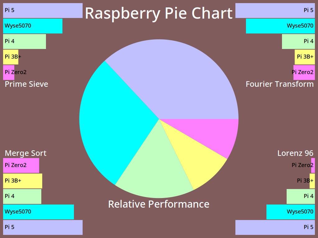
2: pichart
pichart is a processor benchmark developed by Eric Olson for ranking numeric processing power of various computers against Raspberry Pi boards. It’s documented here: A Pi Pie Chart.
It’s possible to tweak this benchmark endlessly with compiler options, but I stuck with whatever version of gcc the system came with. I also used exceptionally conservative compiler options of -O2. I reckon that if your compiler has got to version 12, it won’t be producing terrible code with simple options. Anyway:
All of these are OpenMP multi-core, multi-thread results. The Wyse 5070 holds a pretty solid second place to the Raspberry Pi 5.
3: UnixBench 6.0.0
byte-unixbench must be a very serious benchmark because it wraps a whole suite of results into one impenetrable number. We’re supposed to believe that This Number has some respectable heft. It certainly takes a long time to run (almost half an hour) and if your computer has fans, things can get loud.
Since all three machines have four cores, it’ll save a lot of words to report only the multi-core System Benchmarks Index Score:
For all its purported repeatability, this set of scores surprised me most. The Wyse 5070 doesn’t feel much slower than either Raspberry Pi board. Could the small SATA SSD be a bottleneck? I’d have to spend money to find out.
(I also ran sbc-bench, but the results are even less enlightening. The only thing I could discern was that the Wyse 5070 was running some kind of custom thermal regime. Since it has no fan and only a modest heat-pipe cooler, this is no surprise. My results, have at ’em: sbc-bench)
Conclusions
I can get two Wyse 5070 systems for the cost of one Raspberry Pi 4 or 5. This is what makes the decision for me, and every other issue is window dressing. So much of “I made a thing with a Raspberry Pi!” is really “I made a thing with a small Linux computer!” these days, and the 5070 and other thin clients excel at this.
Yes, the Raspberry Pi 5 is likely to be slightly faster that the Wyse 5070. And if you’re locked-in to their cameras, HATs or GPIO layout, you’re probably going to stick with Raspberry Pi. Likewise, if you’re kitting out a classroom, Raspberry Pis are all repeatable, from the same vendor, and have a proper warranty. Nobody in education got fired for buying Raspberry Pi — even if the micro:bit is the STEM board of choice round these parts.
Even if the supply can be a bit variable, and you can’t be quite sure you’ll be able to get the same spec every time, the Wyse 5070 represents great value for money. I’ll definitely think twice about buying a Raspberry Pi next time.
… about those GPIO pins
If you’re not constrained to using Raspberry Pi’s 40-pin header or specific HAT hardware, you’ve still got options, including but not limited to:
an FT232H Breakout and PyFtdi. It may be possible (with some fiddling) to make the FT232H appear as a Linux gpio chip directly;
and of course, Firmata running on an Arduino is exactly where you left it in 2011. It still works, it hasn’t gone away, and is still at the heart of many custom interactive installations.
Parting thought
“raspberry pi computer” is an anagram of “temporary price burps”. This, I feel, is important for you to know.
this image is supposed to be made almost entirely of sextant blocks, the Unicode characters around U+1FB00 – U+1FB1E made out of two columns of three blocks. They’re originally from broadcast teletext, and were made to build low-resolution images on a text screen
Making the pixel to character map is quite tricky. The Sextant character block isn’t contiguous, and it’s not in the order we need. It’s also missing four characters: empty block, full block, left half block and right half block. These have to be pulled in from other Unicode blocks.
This is the map I came up with, from 0–63 with LSB at bottom right and MSB at top left:
Hey! This code situation may be changing soon, but this article was written about MicroPython v1.25.0 on RP2040. The situation on the Raspberry Pi Pico W / 2W /RP2350 might be quite different.
Many micro-controllers have timed energy-saving modes you can engage when they are idle. These are typically one of:
light sleep: where memory contents are retained, but some parts of the CPU and peripherals are turned off to reduce current;
deep sleep: memory is cleared, most of the CPU and peripherals are powered off. The CPU will reset fully on restart, so your program has to reload.
While MicroPython on the RP2040 has both machine.lightsleep() and machine.deepsleep() functions, there’s not much difference between them. In fact, the deepsleep() routine is merely lightsleep() followed by reset(). So there isn’t any efficiency gain in using deepsleep over lightsleep.
The functions take one argument: the sleep time, given in milliseconds. The largest value that is accepted is 4294966, or (2**32 // 10**3) - 1. That’s 71′ 34″. If you give a larger number, this exception is thrown: ValueError: sleep too long, and the function returns immediately.
If you’ve used machine.deepsleep(), you might want to know whether your micro-controller was started by applying power, or started from the reset() after deepsleep(). The machine.reset_cause() function returns one of two values:
machine.PWRON_RESET: if the CPU was started from power on, or by briefly grounding the RUN pin;
machine.WDT_RESET: if the CPU was soft reset, either by a watchdog timer or other software reset. This is the state returned after deepsleep().
Other MicroPython ports have more nuanced ways of handling sleep and reset states with better power saving.
If you’re running a tight polling loop and still wish to save a little power, machine.idle() is the recommended method.
If you have a Wemos/LOLIN S3 MINI PRO board, you might find that firmware images don’t flash so well. That’s because the ESP32-S3FH4R2 has 4 MB of flash storage, and most ESP32-S3 boards have 8 MB.
This trims down a standard MicroPython ESP32-S3 firmware from a 4 MB filesystem partition down to 2 MB, and sets the overall flash size to 4 MB. Upload that to your board, and all will be well.
Alternatively, v1.26 supports “4MiB and larger” flash chips. I have confirmed that ESP32_GENERIC_S3-20250724-v1.26.0-preview.bin works as expected:
$ mpremote a1 run boardstats.py
Board       : Generic ESP32S3 module with ESP32S3
Frequency   : 160 MHz
Free Memory : 2061232
File storage: 2036 / 2048 K
That Brother laser printer you bought can also pretend it’s a plotter. One of the requirements embedded in a PCL-compatible printer is an implementation of HP-GL/2. This is a slightly modified version of the page description language used by HP’s pen plotters. With care, you can make proofs on a laser printer.
But add some magic header bytes (0x1b, 0x45, 0x1b, 0x25, 0x30, 0x42) and some trailer bytes (0x1b, 0x25, 0x30, 0x41, 0x1b, 0x45), and your printer understands it’s a PCL file.
The file, complete with header and trailer, is here:
full page scan of that HP-GL file as printed on a Brother MFC-L2750DW
HP-GL/2, on mono lasers at least, has some differences to the version used on plotters. The biggest difference is that there’s just one pen. You can change the pattern and line attributes of this pen, but you don’t get to change to multiple pens with different colours.
In late 2024, SparkFun Electronics relaunched their website. In doing so, they deleted roughly 20 years of archived product information, along with all associated datasheets, schematics and tutorials. Luckily, the Internet Archive’s Wayback Machine has good records of the site, and I was able to recover links to 5934 deleted products.
Yes, I was very surprised that the DevEBox STM32H7 at 400 MHz was faster than the 500 MHz MIMXRT1011 in the Metro M7. What was even more impressive is that the STM32H7 board was doing all the calculations in double precision, while all the others were working in single.
As for the other boards, the ESP32 variants performed solidly, but the ESP8266 in last place should be retired. The Raspberry Pi Pico 2 W was fairly nippy, but the original Raspberry Pi Pico is still a lowly Cortex-M0+, no matter how fast you clock it. The STM32F4 boards were slower than I expected them to be, frankly. And yay! to the plucky little W600: it comes in second last, but it’s the cheapest thing out there.
All of these benchmarks were made with the same code, but with two lines changed:
The I2C specification, which is a minor syntax change for each board;
The input trigger pin. Some boards like these as numbers, some take them as strings. Pro tip for W600 users: don’t use D0 for an input that’s tied to ground, unless you want the board to go into bootloader mode …
I’d hoped to run these tests on the SAMD21 little micro-controllers (typically 48 MHz Cortex-M0), but they don’t have enough memory for MicroPython’s framebuf module, so it’s omitted from the build. They would likely have been very slow, though.
In the spirit of fairness, I also benchmarked CircuitPython on a Arduino Nano RP2040 Connect, which has the same processor as a Raspberry Pi Pico:
So it’s about 10% quicker than MicroPython, but I had to muck around for ages fighting with CircuitPython’s all-over-the-shop documentation and ninny syntax changes. For those that like that sort of thing, I guess that’s the sort of thing they like.
Yeah, it’s pretty neat to be able to do that on a Commodore VIC-20 with 5K of RAM. But how about a ZX81 with only 1K? With screen memory that moves around depending on how much stuff you have on the screen? No problem:
that’s it: that’s the whole program
The tricky part is printing just enough to the screen that you have enough memory to store the array and still have enough memory for your program. I did that by printing four lines of “🮐” characters (CHR$ 136 on the ZX81, U+1FB90) and moving the cursor down just far enough that later output wouldn’t zap my data. The screen address (given by the D_FILE pointer at 16396) is used as an array of 100 characters.
The ZX81’s (non-ASCII) character set has a nice quirk that Space is CHR$ 0, and inverse video Space (“█”) is at CHR$ 128. So you can use NOT to toggle the value.
Here’s the program listing, with Unicode characters:
   10 REM 100DOORS1K SCRUSS 2025
  20 FOR I=1 TO 128
  30 PRINT "🮐";
  40 NEXT I
  50 PRINT AT 3,0;"🮐"
  60 LET D=PEEK 16396+PEEK 16397*256
  70 FOR J=1 TO 100
  80 POKE D+J,0
  90 NEXT J
 100 FOR I=1 TO 100
 110 FOR J=I TO 100 STEP I
 120 POKE D+J,128*NOT PEEK (D+J)
 130 NEXT J
 140 NEXT I
 150 FOR I=1 TO 100
 160 IF PEEK (D+I) THEN PRINT I,
 170 NEXT I
The ZX81 program image plus the listing in zmakebas format is included here:
On the left, a Raspberry Pi Pico 2W. On the right, a Raspberry Pi Pico. Each is connected to its own small OLED screen. When a button is pressed, both boards calculate and display the Mandelbrot set, along with its completion time. Needless to say, the Pico 2 W is quite a bit quicker.the before screens …Pico 2 comes in at 10.3 seconds, original Pico at 19.8 seconds
Stuff I found out setting this up:
some old OLEDs, like these surplus pulse oximeter ones, don’t have pull-up resistors on their data lines. These I’ve carefully hidden behind the displays, but they’re there.
Some MicroPython ports don’t include the complex type, so I had to lose the elegant z→z²+C mapping to some ugly code.
Some MicroPython ports don’t have os.uname(), but sys.implementation seems to cover most of the data I need.
On some boards, machine.freq() is an integer value representing the CPU frequency. On others, it’s a list. Aargh.
These displays came from the collection of the late Tom Luff, a Toronto maker who passed away late 2024 after a long illness. Tom had a huge component collection, and my way of remembering him is to show off his stuff being used.
Source:
# benchmark Mandelbrot set (aka Brooks-Matelski set) on OLED
# scruss, 2025-01
# MicroPython
# -*- coding: utf-8 -*-

from machine import Pin, I2C, idle, reset, freq

# from os import uname
from sys import implementation
from ssd1306 import SSD1306_I2C
from time import ticks_ms, ticks_diff

# %%% These are the only things you should edit %%%
startpin = 16  # pin for trigger configured with external pulldown
# I2C connection for display
i2c = machine.I2C(1, freq=400000, scl=19, sda=18, timeout=50000)
# %%% Stop editing here - I mean it!!!1! %%%


# maps value between istart..istop to range ostart..ostop
def valmap(value, istart, istop, ostart, ostop):
    return ostart + (ostop - ostart) * (
        (value - istart) / (istop - istart)
    )


WIDTH = 128
HEIGHT = 64
TEXTSIZE = 8  # 16x8 text chars
maxit = 120  # DO NOT CHANGE!
# value of 120 gives roughly 10 second run time for Pico 2W

# get some information about the board
# thanks to projectgus for the sys.implementation tip
if type(freq()) is int:
    f_mhz = freq() // 1_000_000
else:
    # STM32 has freq return a tuple
    f_mhz = freq()[0] // 1_000_000
sys_id = (
    implementation.name,
    ".".join([str(x) for x in implementation.version]).rstrip(
        "."
    ),  # version
    implementation._machine.split()[-1],  # processor
    "%d MHz" % (f_mhz),  # frequency
    "%d*%d; %d" % (WIDTH, HEIGHT, maxit),  # run parameters
)

p = Pin(startpin, Pin.IN)

# displays I have are yellow/blue, have no pull-up resistors
#  and have a confusing I2C address on the silkscreen
oled = SSD1306_I2C(WIDTH, HEIGHT, i2c)
oled.contrast(31)
oled.fill(0)
# display system info
ypos = (HEIGHT - TEXTSIZE * len(sys_id)) // 2
for s in sys_id:
    ts = s[: WIDTH // TEXTSIZE]
    xpos = (WIDTH - TEXTSIZE * len(ts)) // 2
    oled.text(ts, xpos, ypos)
    ypos = ypos + TEXTSIZE

oled.show()

while p.value() == 0:
    # wait for button press
    idle()

oled.fill(0)
oled.show()
start = ticks_ms()
# NB: oled.pixel() is *slow*, so only refresh once per row
for y in range(HEIGHT):
    # complex range reversed because display axes wrong way up
    cc = valmap(float(y + 1), 1.0, float(HEIGHT), 1.2, -1.2)
    for x in range(WIDTH):
        cr = valmap(float(x + 1), 1.0, float(WIDTH), -2.8, 2.0)
        # can't use complex type as small boards don't have it dammit)
        zr = 0.0
        zc = 0.0
        for k in range(maxit):
            t = zr
            zr = zr * zr - zc * zc + cr
            zc = 2 * t * zc + cc
            if zr * zr + zc * zc > 4.0:
                oled.pixel(x, y, k % 2)  # set pixel if escaped
                break
    oled.show()
elapsed = ticks_diff(ticks_ms(), start) / 1000
elapsed_str = "%.1f s" % elapsed
# oled.text(" " * len(elapsed_str), 0, HEIGHT - TEXTSIZE)
oled.rect(
    0, HEIGHT - TEXTSIZE, TEXTSIZE * len(elapsed_str), TEXTSIZE, 0, True
)

oled.text(elapsed_str, 0, HEIGHT - TEXTSIZE)
oled.show()

# we're done, so clear screen and reset after the button is pressed
while p.value() == 0:
    idle()
oled.fill(0)
oled.show()
reset()
Plug in the CH552 board. You may have to do something with the boot/reset button to make it turn up as the right USB ID (4348:55e0 WinChipHead).
Program the board: sudo ch55xisptool basic52s.bin
Disconnect the board, and wire it up to the USB UART (5 V, GND, TX → RXD [P3.0], RX → TXD [P3.1])
Hit return a few times to get a prompt
PWM is on P1.2, INT1 is on P3.3. See Hackaday project to see how to access I²C, and also do things with SFR values using RDSFR / WRSFR. PORT3 is at SFR(0B0H)
please ignore the following for now …
Who wouldn’t want to run a solid BASIC interpreter on a $3 development board? So maybe there are a couple of drawbacks:
there’s no way to save the program to non-volatile storage: you have to be connected through a serial terminal at all times; and
you’ve got about 600 bytes for the whole program, with no way to expand it.
Despite these limitations, there’s some futile fun to be had. I’ll show you how to flash BASIC-52 onto one of these development boards, and give a quick intro to what you can do with it.
BASIC-52
Intel released the first version of BASIC-52 for their 8051 family of microcontrollers in 1984. They produced a chip (8052AH-BASIC) with the interpreter burnt into mask ROM in 1985. The source code was released into the public domain, and various features such as I²C support were added by the community around 2000.
As befits an embedded language, BASIC-52 supports pin management, timers and interrupts. It’s also a fairly full-featured BASIC interpreter with floating point support and mostly familiar keywords and functions. Because it’s designed for very limited memory use, its string handling is quite unlike any other BASIC dialect. It has one character array that you can treat as a string, and a few functions to work with characters, but that’s about all.
Deqing Sun’s CH552 Stick, from the ch55xduino project
You might know WCH (aka QinHeng Electronics) from their inexpensive CH341 USB serial adapters and other interface boards. What you might not realize is that all of their older interface chips are based on an optimized 8051 design
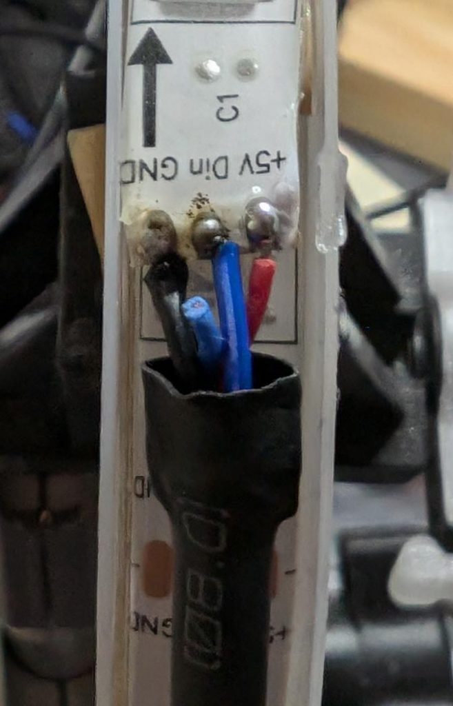
also known as “Monster BASICS Sound reactive RGB+IC Color Flow LED strip”. It’s $5 or so at Dollarama, and includes a USB cable for power and a remote control. It’s two metres long and includes 60 RGB LEDs. Are these really super-cheap NeoPixel clones?
I’m going to keep the USB power so I can power it from a power bank, but otherwise convert it to a string of smart LEDs. We lose the remote control capability.
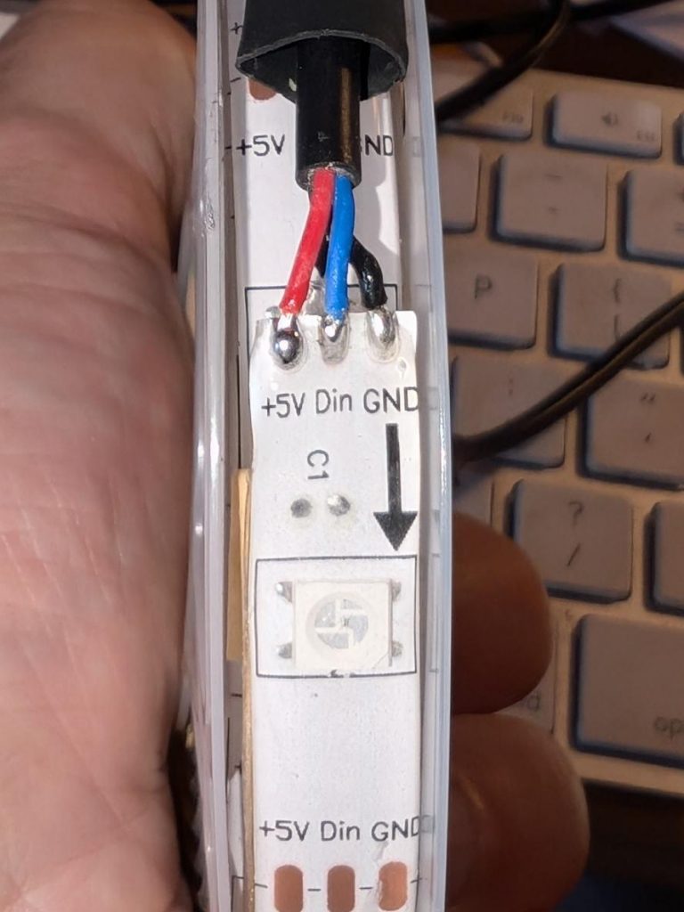
Pull back the heatshrink at the USB end:
… and there are our connectors. We want to disconnect the blue Din (Data In) line from the built in controller, and solder new wires to Din and GND to run from a microcontroller board.
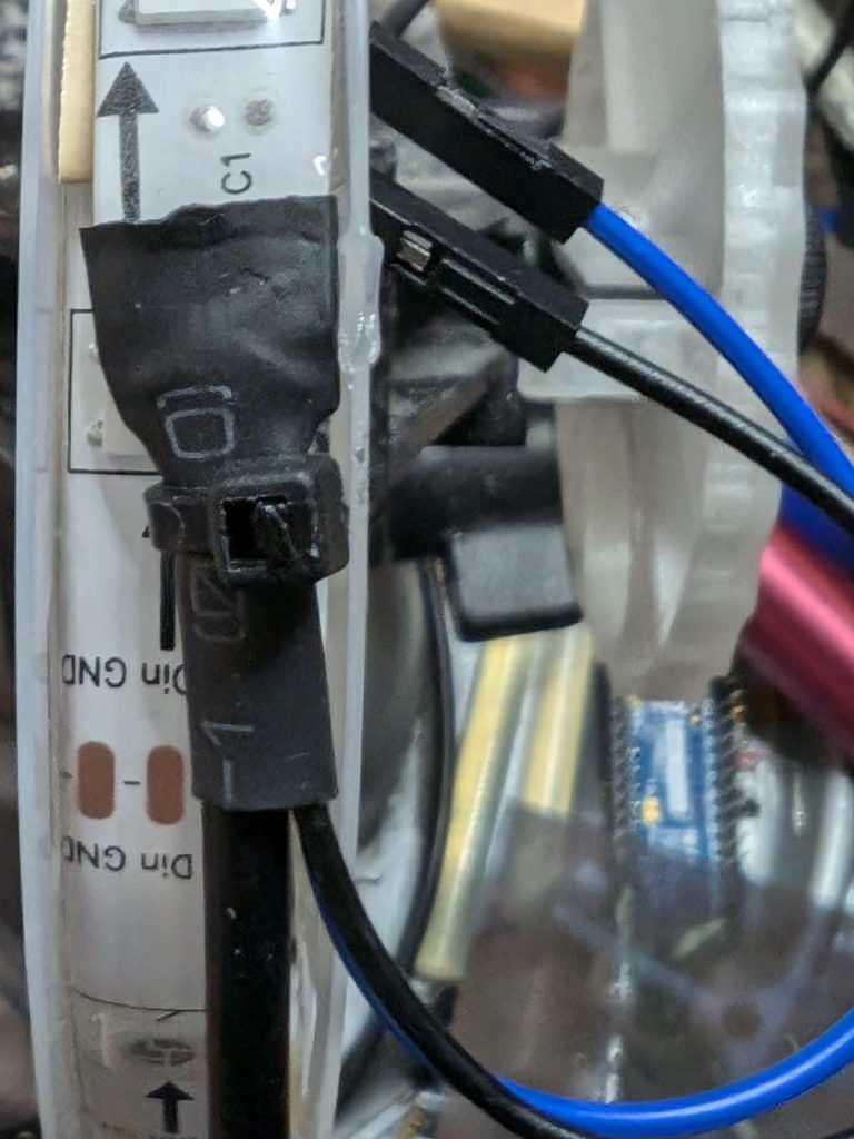
Maybe not the best solder job, but there are new wires feeding through the heatshrink and soldered onto the strip.
Here’s the heatshrink pushed back, and everything secured with a cable tie.
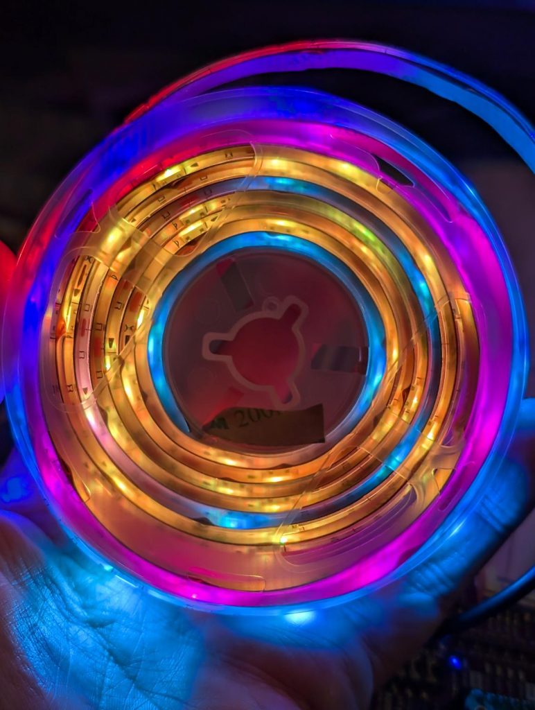
Now to feed it from standard MicroPython NeoPixel code, suitably jazzed up for 60 pixels.
So you bought that Brother laser printer like everyone told you to. And now it’s out of toner, so you replaced the cartridge. If you were in the USA, you could return the cartridge for free using the included label. But in Canada … it’s a whole deal including registering with Brother and giving away your contact details and, and, and …
I’m pretty sure this is a generic label, since:
the file is dated sometime in 2023, and wasn’t generated directly for my download;
I got a different tracking number when I handed the thing in at the post office.
It’s mid-February in Toronto: -10 °C and snowy. The memory of chirping summer fields is dim. But in my heart there is always a cricket-loud meadow.
Short of moving somewhere warmer, I’m going to have to make my own midwinter crickets. I have micro-controllers and tiny speakers: how hard can this be?
more fun than a bucket of simulated crickets (video description: a plastic box containing three USB power banks, each with USB cable leading to a Raspberry Pi Pico board. Each board has a small electromagnetic speaker attached between ground and a data pin)
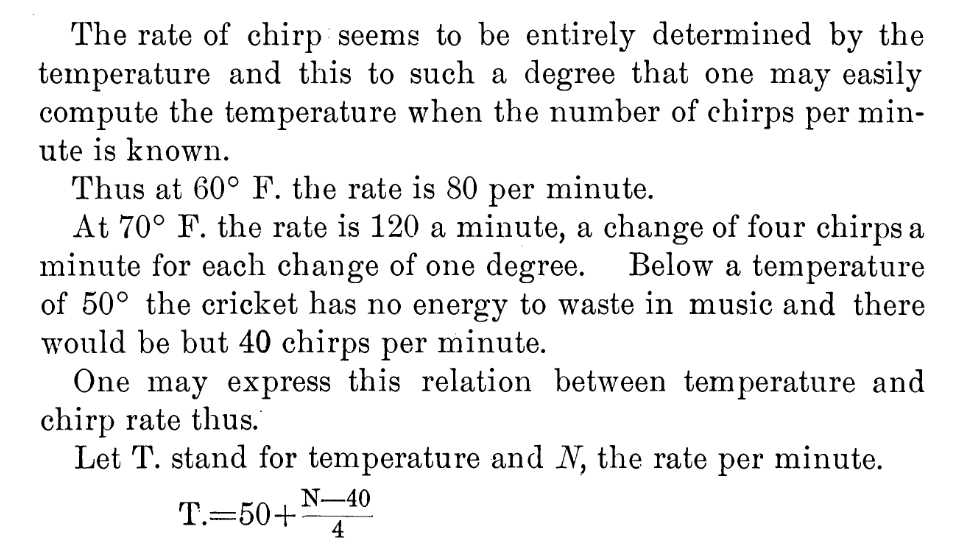
I could have merely made these beep away at a fixed rate, but I know that real crickets tend to chirp faster as the day grows warmer. This relationship is frequently referred to as Dolbear’s law. The American inventor Amos Dolbear published his observation (without data or species identification) in The American Naturalist in 1897: The Cricket as a Thermometer —
pretty bold assertions there without data eh, Amos old son …?
When emulating crickets I’m less interested in the rate of chirps per minute, but rather in the period between chirps. I could also care entirely less about barbarian units, so I reformulated it in °C (t) and milliseconds (p):
t = ⅑ × (40 + 75000 ÷ p)
Since I know that the micro-controller has an internal temperature sensor, I’m particularly interested in the inverse relationship:
p = 15000 ÷ (9 * t ÷ 5 – 8)
I can check this against one of Dolbear’s observations for 70°F (= 21⅑ °C, or 190/9) and 120 chirps / minute (= 2 Hz, or a period of 500 ms):
Now I’ve got the timing worked out, how about the chirp sound. From a couple of recordings of cricket meadows I’ve made over the years, I observed:
The total duration of a chirp is about ⅛ s
A chirp is made up of four distinct events:
a quieter short tone;
a longer louder tone of a fractionally higher pitch;
the same longer louder tone repeated;
the first short tone repeated
There is a very short silence between each tone
Each cricket appears to chirp at roughly the same pitch: some slightly lower, some slightly higher
The pitch of the tones is in the range 4500–5000 Hz: around D8 on the music scale
I didn’t attempt to model the actual stridulating mechanism of a particular species of cricket. I made what sounded sort of right to me. Hey, if Amos Dolbear could make stuff up and get it accepted as a “law”, I can at least get away with pulse width modulation and tiny tinny speakers …
This is the profile I came up with:
21 ms of 4568 Hz at 25% duty cycle
7 ms of silence
28 ms of 4824 Hz at 50% duty cycle
7 ms of silence
28 ms of 4824 Hz at 50% duty cycle
7 ms of silence
21 ms of 4568 Hz at 25% duty cycle
7 ms of silence
That’s a total of 126 ms, or ⅛ish seconds. In the code I made each instance play at a randomly-selected relative pitch of ±200 Hz on the above numbers.
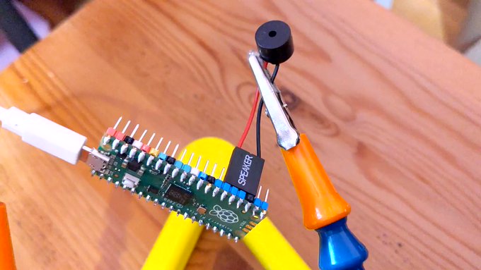
For the speaker, I have a bunch of cheap PC motherboard beepers. They have a Dupont header that spans four pins on a Raspberry Pi Pico header, so if you put one on the ground pin at pin 23, the output will be connected to pin 26, aka GPIO 20:
# cricket thermometer simulator - scruss, 2024-02
# uses a buzzer on GPIO 20 to make cricket(ish) noises
# MicroPython - for Raspberry Pi Pico
# -*- coding: utf-8 -*-

from machine import Pin, PWM, ADC, freq
from time import sleep_ms, ticks_ms, ticks_diff
from random import seed, randrange

freq(125000000)  # use default CPU freq
seed()  # start with a truly random seed
pwm_out = PWM(Pin(20), freq=10, duty_u16=0)  # can't do freq=0
led = Pin("LED", Pin.OUT)
sensor_temp = machine.ADC(4)  # adc channel for internal temperature
TOO_COLD = 10.0  # crickets don't chirp below 10 °C (allegedly)
temps = []  # for smoothing out temperature sensor noise
personal_freq_delta = randrange(400) - 199  # different pitch every time
chirp_data = [
    # cadence, duty_u16, freq
    # there is a cadence=1 silence after each of these
    [3, 16384, 4568 + personal_freq_delta],
    [4, 32768, 4824 + personal_freq_delta],
    [4, 32768, 4824 + personal_freq_delta],
    [3, 16384, 4568 + personal_freq_delta],
]
cadence_ms = 7  # length multiplier for playback


def chirp_period_ms(t_c):
    # for a given temperature t_c (in °C), returns the
    # estimated cricket chirp period in milliseconds.
    #
    # Based on
    # Dolbear, Amos (1897). "The cricket as a thermometer".
    #   The American Naturalist. 31 (371): 970–971. doi:10.1086/276739
    #
    # The inverse function is:
    #     t_c = (75000 / chirp_period_ms + 40) / 9
    return int(15000 / (9 * t_c / 5 - 8))


def internal_temperature(temp_adc):
    # see pico-micropython-examples / adc / temperature.py
    return (
        27
        - ((temp_adc.read_u16() * (3.3 / (65535))) - 0.706) / 0.001721
    )


def chirp(pwm_channel):
    for peep in chirp_data:
        pwm_channel.freq(peep[2])
        pwm_channel.duty_u16(peep[1])
        sleep_ms(cadence_ms * peep[0])
        # short silence
        pwm_channel.duty_u16(0)
        pwm_channel.freq(10)
        sleep_ms(cadence_ms)


led.value(0)  # led off at start; blinks if chirping
### Start: pause a random amount (less than 2 s) before starting
sleep_ms(randrange(2000))

while True:
    loop_start_ms = ticks_ms()
    sleep_ms(5)  # tiny delay to stop the main loop from thrashing
    temps.append(internal_temperature(sensor_temp))
    if len(temps) > 5:
        temps = temps[1:]
    avg_temp = sum(temps) / len(temps)
    if avg_temp >= TOO_COLD:
        led.value(1)
        loop_period_ms = chirp_period_ms(avg_temp)
        chirp(pwm_out)
        led.value(0)
        loop_elapsed_ms = ticks_diff(ticks_ms(), loop_start_ms)
        sleep_ms(loop_period_ms - loop_elapsed_ms)
There are a few more details in the code that I haven’t covered here:
The program pauses for a short random time on starting. This is to ensure that if you power up a bunch of these at the same time, they don’t start exactly synchronized
The Raspberry Pi Pico’s temperature sensor can be slightly noisy, so the chirping frequency is based on the average of (up to) the last five readings
There’s no chirping below 10 °C, because Amos Dolbear said so
The built-in LED also flashes if the board is chirping. It doesn’t mimic the speaker’s PWM cadence, though.
Before I show you the next video, I need to say: no real crickets were harmed in the making of this post. I took the bucket outside (roughly -5 °C) and the “crickets” stopped chirping as they cooled down. Don’t worry, they started back up chirping again when I took them inside.
“If You’re Cold They’re Cold, Bring Them Inside” (video description: a plastic box containing three USB power banks, each with USB cable leading to a Raspberry Pi Pico board. Each board has a small electromagnetic speaker attached between ground and a data pin)
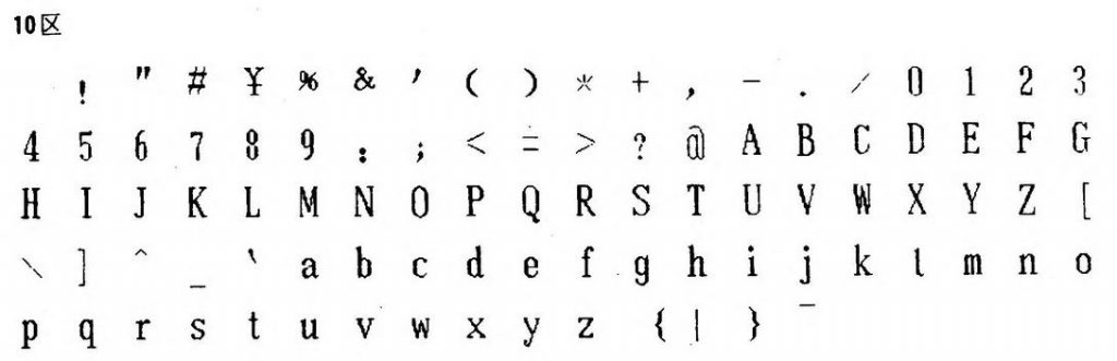
First PostScript font: STSong (华文宋体) was released in 1991, making it the first PostScript font by a Chinese foundry [ref: Typekit blog — Pan-CJK Partner Profile: SinoType]. But STSong looks like Garamond(ish).


![[decorative] a spiralling figure made of scaled and rotated equilateral triangles](https://scruss.com/wordpress/wp-content/uploads/2025/04/hpgl-rotatey.png)
![[decorative] a spiralling figure made of scaled and rotated equilateral triangles](https://scruss.com/wordpress/wp-content/uploads/2025/04/20250408_214147_BRWD89C6730425A_000572a-787x1024.jpg)


![A table of the latin characters @, A-Z, [, \, ], ^, _, `, a-z and { in STSong half-width latin, taken from fontforge](https://scruss.com/wordpress/wp-content/uploads/2024/01/Screenshot-from-2024-01-07-11-44-09.png)