Instagram filter used: Lo-fi
The Earl of Northumberland had dismissed as mere bragging the expressed intention of the Scottish government to try to do something about the Liddesdale robbers. Like Sim the Laird, he believed the Armstrongs were far too powerful for King James. But he was wrong. The young king had undertaken to “proceed to the sharpe and rygorouse pwnyssching of all transgressioune apone the bordourisâ€, and he now went to work, beginning with a gentle approach.
— from The Steel Bonnets, by George MacDonald Fraser, chapter 27.
Yes, the Scots. We may have been the bunk at spelling, but we’ve been pwning since 1529.
After doing almost nothing with the Arduino and the elusive Power Cost Monitor signal, I’m finally getting something from it. Matt Colyer’s Power Monitor sketch does all the heavy lifting, for he managed to reverse engineer the protocol. His solution is a rather complex one, involving ethernet shields and Ruby. All I wanted was a simple serial logger, so I cut down Matt’s code, and modified the network output to simple print statements:
== Waiting (38464857ms, 1676 bytes) ==
== Sending (38467858ms, 1668 bytes) ==
sample[data]=0000000a
sample[data]=0000015a
== Waiting (38467863ms, 1676 bytes) ==
== Received (38592156ms, 1670 bytes) ==
== Waiting (38592157ms, 1676 bytes) ==
== Sending (38595158ms, 1668 bytes) ==
sample[data]=00000000
== Waiting (38595159ms, 1676 bytes) ==
== Received (38624334ms, 1670 bytes) ==
== Waiting (38624335ms, 1676 bytes) ==
== Sending (38627336ms, 1668 bytes) ==
sample[data]=ffffe746
== Waiting (38627337ms, 1676 bytes) ==
== Received (38688007ms, 1670 bytes) ==
== Waiting (38688009ms, 1676 bytes) ==
== Received (38688045ms, 1670 bytes) ==
== Waiting (38688046ms, 1676 bytes) ==
== Sending (38691047ms, 1668 bytes) ==
sample[data]=00001748
sample[data]=00000008
== Waiting (38691052ms, 1676 bytes) ==
== Received (38720026ms, 1670 bytes) ==
== Waiting (38720027ms, 1676 bytes) ==
== Sending (38723028ms, 1668 bytes) ==
sample[data]=00000000
== Waiting (38723030ms, 1676 bytes) ==
== Received (38783686ms, 1670 bytes) ==
== Waiting (38783687ms, 1676 bytes) ==
== Sending (38786688ms, 1668 bytes) ==
sample[data]=00000011
== Waiting (38786689ms, 1676 bytes) ==
== Received (38815636ms, 1670 bytes) ==
== Waiting (38815637ms, 1676 bytes) ==
== Sending (38818638ms, 1668 bytes) ==
sample[data]=fffff322
== Waiting (38818639ms, 1676 bytes) ==
== Received (38847547ms, 1670 bytes) ==
== Waiting (38847548ms, 1676 bytes) ==
== Sending (38850549ms, 1668 bytes) ==
sample[data]=00000001
== Waiting (38850550ms, 1676 bytes) ==
== Received (38879444ms, 1670 bytes) ==
== Waiting (38879446ms, 1676 bytes) ==
== Sending (38882445ms, 1668 bytes) ==
sample[data]=0000374f
== Waiting (38882446ms, 1676 bytes) ==
== Received (38911210ms, 1670 bytes) ==
== Waiting (38911211ms, 1676 bytes) ==
== Sending (38914212ms, 1668 bytes) ==
sample[data]=00000043
== Waiting (38914213ms, 1676 bytes) ==
== Received (39006981ms, 1670 bytes) ==
== Waiting (39006982ms, 1676 bytes) ==
== Sending (39009982ms, 1668 bytes) ==
sample[data]=00000000
== Waiting (39009983ms, 1676 bytes) ==
== Received (39038895ms, 1670 bytes) ==
== Waiting (39038896ms, 1676 bytes) ==
== Sending (39041897ms, 1668 bytes) ==
sample[data]=00000001
== Waiting (39041898ms, 1676 bytes) ==
== Received (39102999ms, 1670 bytes) ==
== Waiting (39103000ms, 1676 bytes) ==
== Sending (39106001ms, 1668 bytes) ==
sample[data]=00000000
== Waiting (39106002ms, 1676 bytes) ==
== Received (39134880ms, 1670 bytes) ==
== Waiting (39134881ms, 1676 bytes) ==
== Sending (39137882ms, 1668 bytes) ==
sample[data]=00000001
== Waiting (39137883ms, 1676 bytes) ==
Now it’s just a small matter of programming to work out what Matt’s Ruby code does. Ruby always looks to me like two programmers started coding at different ends of the same line, and collided in the middle. I’m hoping there’s enough processing power in the Arduino to do the conversion in the chip, and output useful log data as a serial stream.
More later …
I don’t often need it, but the code printing facility in the Arduino IDE is very weak. It has some colour highlighting, but no page numbering, no line numbering, and no headers at all.
a2ps will sort you right out here. Years back, it was a simple text to PostScript filter, but now it has many wonderful filters for pretty-printing code. The Wiring/Arduino language is basically C++, and a2ps knows how to deal with that. So, to create a PostScript file with a nice version of the the most basic Blink sketch:
a2ps --pro=color -C -1 -M letter -g --pretty-print='c++' -o ~/Desktop/Blink.ps Blink.ino
If you’re somewhere that uses sensible paper sizes (in other words, not North America), you probably don’t want the -M letter option. a2ps is supposed to have a PDF print option (. You can’t use the -P pdf), but it doesn’t work on my installation, so I just splat the output through ps2pdf-P «printer» option combined with the -o «file» option, but cups-pdf is your friend if you need to print to a PDF. The results are linked below:

Not bad, eh?
(Update: think I must have written this post on a Mac with a case-insensitive filesystem. Using the --pretty-print='C++' option I had before failed on Linux.)

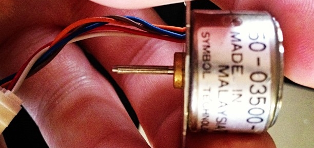
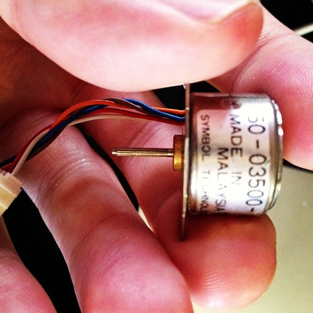
Active Surplus Electronics is the best. I was wanting to learn about driving stepper motors from a microcontroller, but didn’t want to spend a lot or rig up a complex power supply. Active Surplus had a bin of tiny 5V stepper motors at under $3 each. The one I bought is marked:
50-03500-    028
MADE IN
 MALAYSIA   7115
SYMBOL TECHNOLOGIES, INC.
I have no data sheet, but I’ve been able to work out that it’s a unipolar stepper motor, 20 steps/revolution (18°/step; quite coarse), wired:
It’s small enough to be driven directly by USB power through an Arduino and the Adafruit Motor Shield. No idea how much torque this thing puts out, but it can’t be much.
(Setting up my motor shield was a pain, as I’d accidentally put non-stacking headers on it. This required an hour of swearing-filled desoldering; lead-free through-hole desoldering is just the worst*. With wick and solder pump, I finally managed to clear everything up well enough to fit the new headers.)
(more…)

Yay! My article on Arduino and Raspberry Pi is this month’s cover of The MagPi! Read it on Issuu, or download the PDF.
Thanks to Ash and the rest of the team at the magazine.
Hey! This article is really old! So old, in fact, that I clearly thought that saying (ahem) “w00t w00t†was a good idea. Information here may be misleading and possibly wrong. You probably want to be using a newer client library and you definitely want to use an Arduino IDE ≥ 1.6 and not the ancient one that comes with Raspbian.
pyFirmata‘s documentation is, to be charitable, sparse. After writing Raspberry Pi, Python & Arduino *and* a GUI (which should be making an appearance in The MagPi soon, w00t w00t yeet!), I looked at pyFirmata again to see what it could do. That pretty much meant digging through the source.
Firmata can drive hobby servos, and if you’re not driving too many, you can run them straight from the Arduino with no additional power. I used a standard cheapo-but-decent Futaba S3003, which gives you about 180° of motion. The particular one I tried started to make little growly noises past 175°, so in the example below, that’s hardcoded as the limit.
#!/usr/bin/python
# -*- coding: utf-8 -*-
# move a servo from a Tk slider - scruss 2012-10-28

import pyfirmata
from Tkinter import *

# don't forget to change the serial port to suit
board = pyfirmata.Arduino('/dev/tty.usbmodem26271')

# start an iterator thread so
# serial buffer doesn't overflow
iter8 = pyfirmata.util.Iterator(board)
iter8.start()

# set up pin D9 as Servo Output
pin9 = board.get_pin('d:9:s')

def move_servo(a):
    pin9.write(a)

# set up GUI
root = Tk()

# draw a nice big slider for servo position
scale = Scale(root,
    command = move_servo,
    to = 175,
    orient = HORIZONTAL,
    length = 400,
    label = 'Angle')
scale.pack(anchor = CENTER)

# run Tk event loop
root.mainloop()
The code above makes a slider (oh, okay, a Tkinter Scale widget) that moves the servo connected to Arduino pin D9 through its whole range. To set the servo position, you just need to write the angle value to the pin.
I haven’t tried this with the Raspberry Pi yet. It wouldn’t surprise me if it needed external power to drive the Arduino and the servo. This might be a good excuse to use my Omega-328U board — it’s Arduino code compatible, runs from an external power supply, and has Signal-Voltage-Ground (SVG) connectors that the servo cable would just plug straight into.
I would have been posting more Raspberry Pi posts, but my latest Made-in-UK 512MB board seems to have a raft of problems. Left to its own devices, it will happily corrupt any SD card I put in it. This is some fairly typical dmesg output:
[36218.109865] mmc0: final write to SD card still running

[36228.126345] mmc0: Timeout waiting for hardware interrupt - cmd12.

[36228.127534] mmcblk0: error -110 sending stop command, original cmd response 0x900, card status 0x900

[36248.152121] mmc0: final write to SD card still running

[36258.163655] mmc0: Timeout waiting for hardware interrupt - cmd12.

[36258.164865] mmcblk0: error -110 sending stop command, original cmd response 0x900, card status 0x900

[36269.084446] mmc0: final write to SD card still running

[36279.101766] mmc0: Timeout waiting for hardware interrupt - cmd12.

[36279.102953] mmcblk0: error -110 sending stop command, original cmd response 0x900, card status 0x900

[36309.899006] mmc0: Timeout waiting for hardware interrupt - cmd25.

[36309.899047] mmc0: resetting ongoing cmd 25DMA before 4096/4096 [84]/[96] complete

[36309.902774] mmcblk0: error -110 transferring data, sector 1721928, nr 848, cmd response 0x900, card status 0xc00

[36309.902964] mmc0: DMA IRQ 6 ignored - results were reset

[36309.903200] end_request: I/O error, dev mmcblk0, sector 1722649

[36309.903227] end_request: I/O error, dev mmcblk0, sector 1722656

...

[36309.903462] end_request: I/O error, dev mmcblk0, sector 1722768

[36309.903823] Aborting journal on device mmcblk0p2-8.

[36310.460263] journal commit I/O error

[36310.653420] EXT4-fs error (device mmcblk0p2): ext4_journal_start_sb:327: Detected aborted journal

[36310.667118] EXT4-fs (mmcblk0p2): Remounting filesystem read-only
I’m not alone in having this problem; it’s reported by other people at Raspberry Pi • PI freezes and Filesystem corruption on the SD card – Stack Exchange. I don’t see any solutions or responses from the Foundation yet.
Update: for no reason I can explain, setting over_voltage=2 in the /boot/config.txt file seems to make this problem go away. For me, at least.
Perhaps the only disadvantage of riding a Dutch bike like my Batavus is that it uses so many parts that are unknown outside Europe. Simple things like replacing the batteries in the rear light are much harder than they need to be. There are no manuals in English for these parts, and since Batavus’s guidelines start and end at “Take it to your bike shop”, it’s not much help.
The low battery light on my rear LED had just started to glow, so I had to replace the batteries. With no discernible way in, this was tricky. You have to unscrew the two Phillips screws on the reflector, and kind of slide the reflector and batteries straight back and off:

It would be a lot easier to leave the light on the carrier, as it would give you a tonne more leverage. There’s a thumbnail indentation at the bottom of the light to help with this removal, but I had to use a small plastic drift from my electronics toolkit. (Please excuse my manky nails in the picture; I’d been gardening.)
My light says it’s a “Smart Co., Ltd TL271R//RC” on the back, and may be sold under other brands. It’s suspiciously similar to the Move Shaphire 271 rear light. I’m not really complaining — this is the first new set of batteries I’ve had to fit since I bought the bike in February 2009.
Update: hey, who knew? Even folks from the Netherlands are searching for this blog entry. That’s if my site stats for “move fietslicht batterij vervangen” are to be believed …
Withered Hand is one of my favourite artists. Today, I found out that one of his first EPs was for Paul Carter, my childhood friend who died in 2006. Paul’s artwork is on the cover.
I’m not ashamed to say that I cried my eyes out when I heard Big Ten Four (Paul’s Song).
I know a lot of people who bought the Texas Instruments MSP430 LaunchPad development kit but never really got into it. I’m one of them; the $4.30 purchase price was compelling, but the requirement to install a huge proprietary IDE (with its own embedded C dialect) was just too much.
For this reason, Energia is great. It’s a fork of the Wiring/Arduino development environment for the MSP430. Looks just like Arduino, but quite red:

The basics of the language are the same, although the pin names and functions are different from the Arduino. The basic board also has a red and a green LED, a user button, and the obligatory reset button.
Just to try out Energia, I wanted a useful project that only used the onboard hardware. I came up with a version of a pomodoro timer, similar to the one used in The Pomodoro Technique® time management method. The one I made has the following features:
For me, this electronic version has several advantages over the wind-up official timer:
It does have a couple of possible disadvantages, though:
Here’s the code (tested on a MSP-EXP430G2 board, version 1.4):
/*

 launchpomodoro - simple task/rest timer for TMS430/Energia

 On reset: Green LED on for 25 minutes
 After 25 minutes: Red LED
 After 30 minutes: Flashing Red/Green LED (until reset)
 On button press: all lights off.

 scruss - 2012-10-15

 */

// 25 minutes
#define ENDWORKTIME 1500000
// 30 minutes
#define ENDRESTTIME 1800000

unsigned long start=0;
int red=1; // for light flashing state at end of rest time
int green=0;

void setup() {
  pinMode(GREEN_LED, OUTPUT);
  pinMode(RED_LED, OUTPUT);
  pinMode(PUSH2, INPUT);
  digitalWrite(GREEN_LED, HIGH); // start work
  digitalWrite(RED_LED, LOW); // stop rest
  start=millis();
}

void loop () {
  if ((millis()-start)>ENDWORKTIME) {
    digitalWrite(GREEN_LED, LOW); // stop work
    digitalWrite(RED_LED, HIGH); // start rest
  }

  if ((millis()-start)>ENDRESTTIME) {
    flicker(); // warn that we've overrun
  }

  if (digitalRead(PUSH2) == LOW) { // push quiet/off switch
    off();
  }
}

void flicker() { // toggle LEDs and wait a bit
  red=1-red;
  green=1-green;
  digitalWrite(GREEN_LED, green);
  digitalWrite(RED_LED, red);
  delay(333);
}

void off() { // appear to be off
  digitalWrite(GREEN_LED, LOW); // lights off
  digitalWrite(RED_LED, LOW);
  while (1) { // loop until reset
    delay(50);
  }
}
(or if you’d rather have the archived sketch: launchpomodoro-121015a.zip.)
It would be trivial to port this to Arduino, but you would need some external LEDs, resistors and a pushbutton.