Instagram filter used: Hudson
 I’m very taken with Ariel Rojo‘s Piggy Bank Lamp. It’s the first ornament I’ve seen that uses the form of a compact fluorescent bulb as an integral part.
Not sure I’m quite taken enough with it to pay the $98 that the AGO store wants, though …
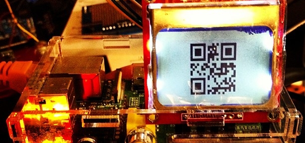
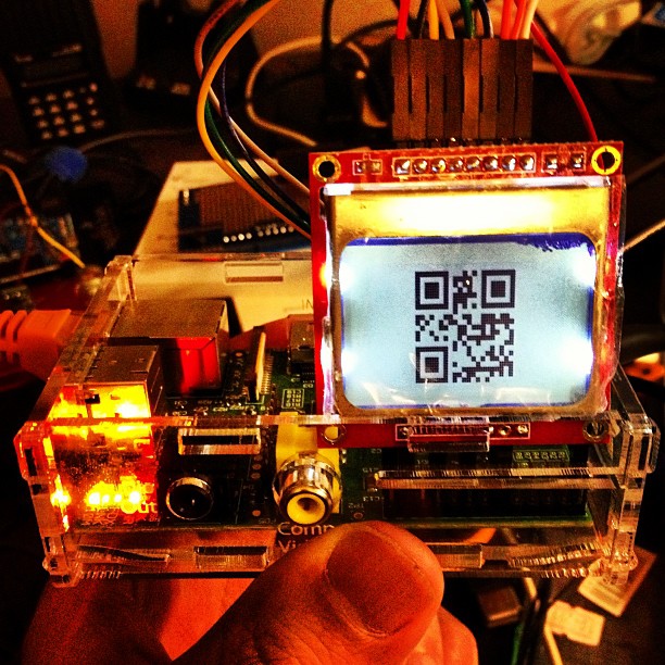
I have, of late, been rather more attached to QR Codes than might be healthy. I’ve been trying all sorts of sizes and input data, printing them, and seeing what camera phones can scan them. I tried three different devices to scan the codes:
QR Code readability is defined by the module size; that is, the number of device pixels (screen or print) that represent a single QR Code pixel. Denso Wave recommends that each module is made up of 4 or more dots. I was amazed that the iPhone could read images with a module size of 1 from the screen, like this one:

On this laptop, one pixel is about 0.24 mm. The other cameras didn’t fare so well on reading from the screen:
So I guess for screen scanning, Denso Wave’s recommendation of 4 pixels/module will pretty much work everywhere.
I then generated and printed a bunch of codes on a laser printer, and scanned them. The results were surprisingly similar:
A test print on an inkjet resulted in far less impressive results. I reckon you need to make the module size around 25% bigger on an inkjet than a laser, perhaps because the inkjet is less crisp.
I have to admit I went a bit nuts with QR Codes. I made a Vcard: 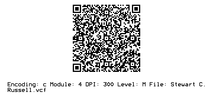
(and while I was at it, I created a new field for ham radio operators: X-CALLSIGN. Why not?). I even encoded some locations in QR Codes.
Just to show you what qrencode can do, here’s a favourite piece of little prose:

Hey! This article is really old. The advice given here will not work on a Raspberry Pi 3, and will need some care with recent versions of Raspbian.
Sometimes you find a computer component that’s so cheap, that works so well, that you’re amazed you managed to live without it for so long. The JY-MCU Arduino Bluetooth Wireless Serial Port Module is that component for me right now.
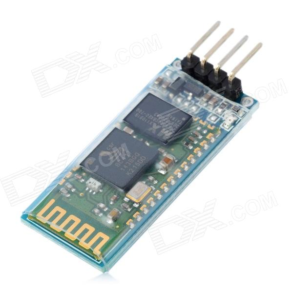
This little board is a cheap ($8.50!) Bluetooth serial port. It’s happy with the Raspberry Pi’s 3.3 V logic levels, and will communicate at standard rates between 1200 and 1,382,400 baud. It even comes with a nifty little cable which is just the right polarity for the Raspberry Pi’s GPIO pins. It’s really meant to do serial comms on an Arduino, but it’s not limited to that.
What this board allows you to do is connect to your Raspberry Pi’s serial console via Bluetooth. That way, you can have your Raspberry Pi hidden away somewhere, and yet still log in as if you were talking to it directly through a serial cable. Combine this with a USB wireless adaptor (like the Belkin N150 that I use) and you’ve got a wireless device you can always connect to, even if your network goes down.
In order to use this device with your Raspberry Pi, you’re going to have to do some reconfiguration. Exactly what reconfiguration you do depends on some additional hardware:
(I chose this option, as it allows me to use the Bluetooth module with Firmata on an Arduino, too.)
The JY-MCU board comes with no instructions, but all the reconfiguration commands you’ll need are explained here: hc06_linvor_1.5_at_command_set [[hc06_linvor_1.5_at_command_set]] (cached copy; original has gone) While you’re setting the communications speed, you’ll probably also want to change the device name (so you can more easily recognize your own board, as the default is something like “Linvor”) and PIN (for that warm feeling of security that only a four digit code can provide). The device is configured using AT commands (or as we eldsters call them, Hayes commands) by plugging it directly into a USB-TTL Serial device attached to your computer. Here’s how you wire it:
USB-TTL Serial    Bluetooth Serial
================= =================
GND               GND
VCC               VCC
TXD               RXD
RXD               TXD
Note that TXD and RXD are crossed. The Bluetooth unit runs on a 3.6-6V supply, but 3.3V logic. To enter the AT commands, start a serial terminal (Hyperterm, minicom, screen …) at 9600 baud talking to the USB-Serial adapter, and copy and paste these commands in:
AT+NAMEBluey
AT+PIN4321
AT+BAUD8
You’ll have to disconnect the terminal and reconnect at 115,200 baud, as that last command just reset the Bluetooth device’s speed. You might want to use other settings than Bluey for the name and 4321 for the PIN, too.
Update: check that your Raspberry Pi’s /boot/cmdline.txt contains:
console=ttyAMA0,115200
You will not get a login prompt otherwise.
Now go to Using the Device.
Serial terminals traditionally ran at 9600 baud, and that seems a bit slow these days. But, if you don’t have a way of setting up the Bluetooth device differently, 9600 is what you’re stuck with. You’ll need to edit your Raspberry Pi’s /boot/cmdline.txt so that the part that previously read:
console=ttyAMA0,115200 kgdboc=ttyAMA0,115200
to
console=ttyAMA0,9600 kgdboc=ttyAMA0,9600
Note that this file should only contain one line, so be careful you don’t add extra line breaks or your Raspberry Pi won’t boot. Save the file, reboot your Raspberry Pi, and go to the next section.
Using the Device
On your Raspberry Pi, connect the Bluetooth Wireless Serial Port Module as follows:
Raspberry Pi      Bluetooth Serial
================= =================
5V  (GPIO Pin  2) VCC
GND (GPIO Pin  6) GND
TXD (GPIO Pin  8) RXD
RXD (GPIO Pin 10) TXD
(Despite the minimum 3.6V rating, I’m happily running mine from the 3V3 power, GPIO Pin 1. YMMV.)
When the board gets power, but isn’t paired, the LEDs on the Bluetooth module flash quickly. Now you need to pair the device with your computer (use 0000 as the PIN, or whatever you chose if you changed it), and it will appear as a serial port on your machine. On my Mac, that’s a device called /dev/tty.Bluey-DevB. The LEDs stop flashing when the port goes into use. Open up a serial terminal, set the device and speed correctly, and if all goes well, you should see:
Debian GNU/Linux wheezy/sid raspberrypi ttyAMA0

raspberrypi login:
Success!

archived from MP3: Black Walls — Gabriel’s Message | Silent Shout — Canadian indie electronic music blog and Toronto DJ night as the original SoundCloud link is gone.


Random fills of Hoop Tiles, perhaps slightly influenced by 10 PRINT.