
Instagram filter used: Lo-fi
Unless you have the heavy analogue Apple CRT that was specially made for it, composite video output on the Apple IIgs is utterly dismal:
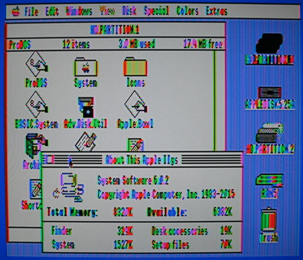
Adding an Apple IIgs → SCART cable through a SCART to HDMI converter is much better:

There’s still a little bit of shimmer to the background, but at least text is legible.
Thank you for the music, Scott. This is how I’ll remember you, lighting up the crowd on a warm Toronto evening:

Frightened Rabbit’s Scott Hutchison: a songwriter who found humanity in our flaws
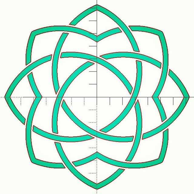

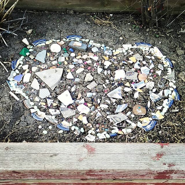
Yup, lots of circles, intersections, differences and offsets went into this attempt at the logo of my favourite museum.
For the determined/demented, here’s the source. It’s probably not that useful for learning OpenSCAD, as it’s written in my typical “carve away all the bits that don’t look like an elephant†style:
// akm logo - why yes this *is* a good tool to use ...

// constants for octagon maths
r1 = 1 - sqrt(2) / 2;           // ~0.292893
r2 = sqrt(r1);                  // ~0.541196
x1 = (sqrt(2) - 1) / 2;         // ~0.207107

sc = 100;                       // size factor
t = 4;                          // line thickness
bigt = 7;                       // strapwork gap thickness
$fn = 256;                      // OpenSCAD circle smoothness

module petal() {
    intersection() {
        translate([ sc * x1, sc * x1])circle(r = sc * r2);
        translate([-sc * x1, sc * x1])circle(r = sc * r2);
    }
}

module hollow_petal() {
    difference() {
        offset(r =  t / 2)petal();
        offset(r = -t / 2)petal();
    }
}

module inner_lobe() {
    difference() {
        for (i = [0:3]) {
            rotate(i * 90 + 45)offset(r = t / 2)petal();
        }
        for (i = [0:3]) {
            rotate(i * 90 + 45)offset(r = -t / 2)petal();
        }
    }
}

module ring() {
    for (i = [0:3]) {
        rotate(i * 90)difference() {
            intersection() {
                inner_lobe();
                union() {
                    offset(r = -bigt / 2)petal();
                    rotate(45)offset(r = t / 2)petal();
                }
            }
            rotate(90)offset(r = bigt / 2)petal();
        }
    }
}

module logo() {
    union() {
        ring();
        for (i = [0:3]) {
            rotate(90 * i)union() {
                intersection() {
                    hollow_petal();
                    rotate(-90)offset(r = -bigt / 2)petal();
                }
                difference() {
                    intersection() {
                        hollow_petal();
                        rotate(45)offset(r = -bigt / 2)petal();
                    }
                    rotate(-90)offset(r = bigt / 2)petal();
                }

                difference() {
                    hollow_petal();
                    offset(r = bigt / 2)union() {
                        rotate(-90)petal();
                        rotate(45)petal();
                    }
                }
            }
        }
    }
}

logo();
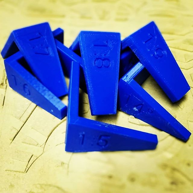
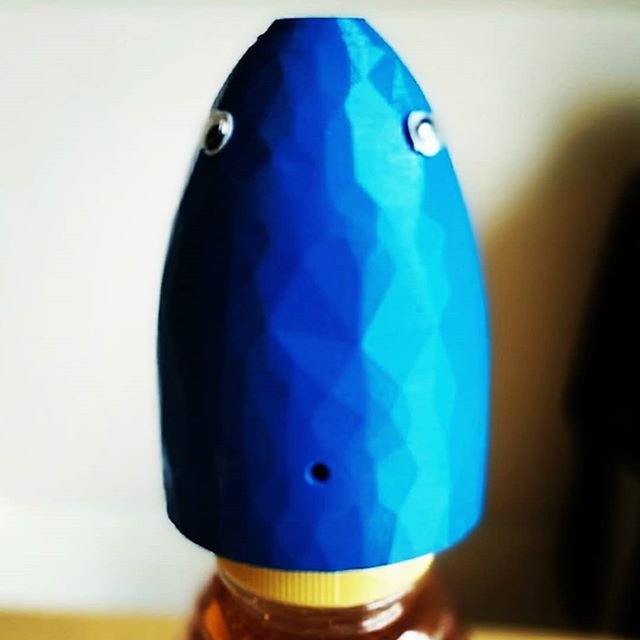
I use a FlashForge Creator Pro 3D printer for work. It’s okay, but I wouldn’t recommend it: you have to manually level the print bed (ಠ_ಠ), you can’t print via USB, it pretends to be a knock-off MakerBot (same USB ID: naughty naughty) and its slicing software is a mishmash of GPL and other code all bundled up in one proprietary lump. It also doesn’t used g-code, which is a bit poo.
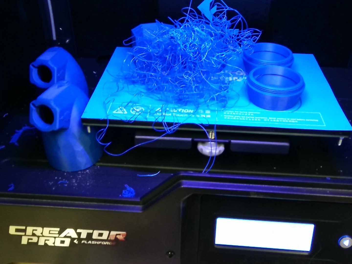
I have been having endless trouble will tall prints losing adhesion, falling over, and leaving a noodly mess everywhere. I’ve fixed it by making some manual changes to the config file, the process as described here: Flashprint advanced print settings by editing the default.cfg configuration file. What I changed was:
[brim]
enable = true                  # valid range {true, false}, default is false # CHANGED
extruderId = 0                  # valid range {0, 1}, default is 0
margin = 10.0                    # valid range [1.0, 10.0], default is 5.0   # CHANGED
layerCnt = 2                    # valid range [1, 5], default is 1           # CHANGED
speed = 60                      # valid range [10, 200], default is 60
excludeInterior = true         # valid range {true, false}, default is false # CHANGED
This makes a colossal double-width, double thickness brim around the prints so that they will not topple. I’m very happy with the results so far.
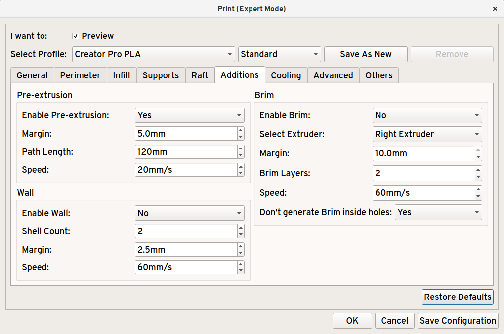
Rather than mucking about with config files, if you enable “Expert Mode” in Flashprint’s preferences:
![]()
Then you can make a brim that stops prints coming off the print bed.
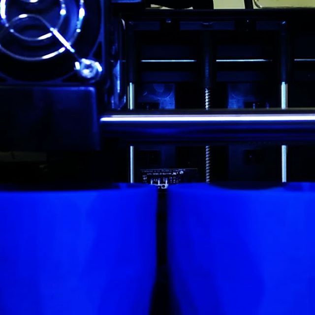
And lo, there was much rejoicing …

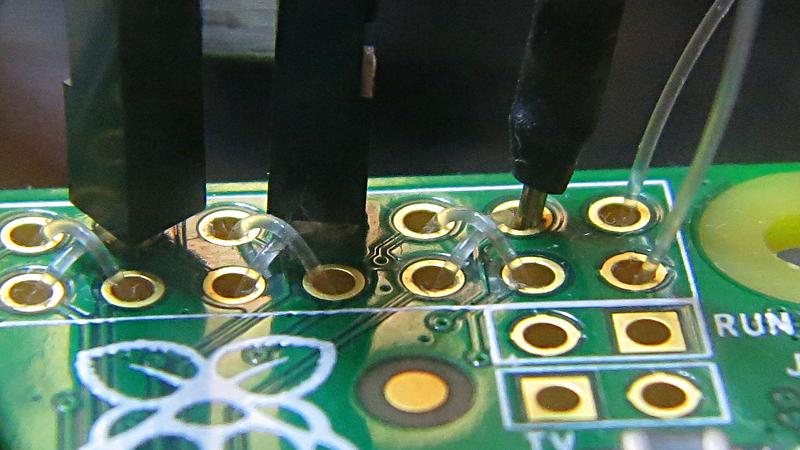
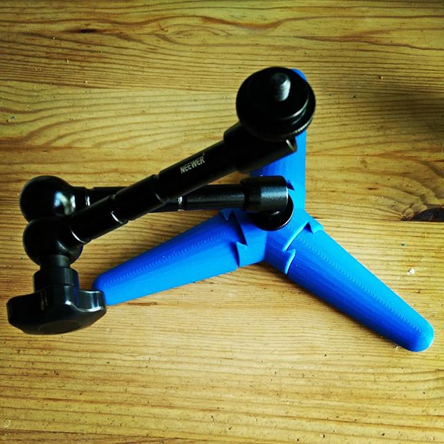
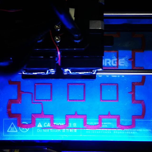
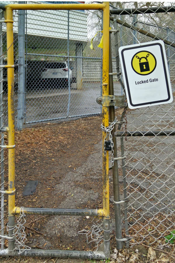
Eugene “thirtytwoteeth” Andruszczenko (of Game Boy Zero – Handheld Edition fame) posted a neat idea to help your Raspberry Pi Zero take jumper wires without soldering. He threaded fishing line through the 40 hole header, making an interference fit for header pins. I tried it with 0.38 mm Trilene, which worked rather well.
Instagram filter used: Lo-fi
… which of course failed 95% through:
You gotta brim all the time.