Niche Knowledge: Z80 parallel port SD card on Zeta2

green circuit board with secure digital card slot on left and 40-pin parallel interface connectors on the right
Mini PPISD board: a slow SD card mass-storage system for 8-bit computers

Almost no-one will need this knowledge, but I might need to remember it. In order to add Mini PPISD support to a RomWBW 3.01-supported system, you need to create a file called something like Source/HBIOS/Config/ZETA2_ppisd.asm (for yes, I’m using a Zeta SBC V2) containing:

#include "cfg_zeta2.asm"
UARTCFG		.SET	UARTCFG | SER_RTS
CRTACT		.SET	TRUE		
PPIDEENABLE	.SET	FALSE		
SDENABLE	.SET	TRUE		
PPPENABLE	.SET	FALSE		
PPISD		.EQU	TRUE

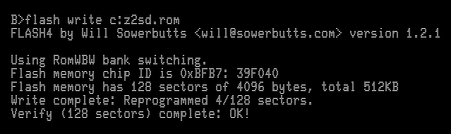
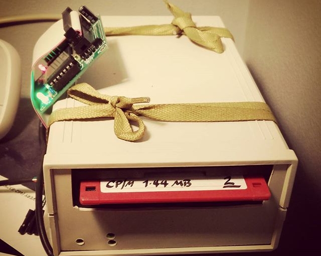
Running make from the top-level directory should create a ROM image called Binary/ZETA2_ppisd.rom for you to write to flash. Since my floppy drive isn’t feeling too happy, I had to resort to buying a TL866II Plus programmer to write the chip.

And it worked!

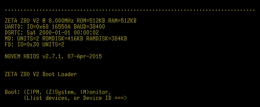
 RomWBW HBIOS v3.0.1, 2021-03-12

 ZETA V2 Z80 @ 8.000MHz
 0 MEM W/S, 1 I/O W/S, INT MODE 2
 512KB ROM, 512KB RAM

 CTC: MODE=Z2 IO=0x20
 UART0: IO=0x68 16550A MODE=38400,8,N,1
 DSRTC: MODE=STD IO=0x70 Sun 2021-03-14 17:47:13 CHARGE=OFF
 MD: UNITS=2 ROMDISK=384KB RAMDISK=384KB
 FD: IO=0x30 UNITS=2
 SD: MODE=PPI IO=0x60 DEVICES=1
 SD0: SDSC NAME=SD    BLOCKS=0x003C7800 SIZE=1935MB

 Unit        Device      Type              Capacity/Mode
 ----------  ----------  ----------------  --------------------
 Char 0      UART0:      RS-232            38400,8,N,1
 Disk 0      MD1:        RAM Disk          384KB,LBA
 Disk 1      MD0:        ROM Disk          384KB,LBA
 Disk 2      FD0:        Floppy Disk       3.5",DS/HD,CHS
 Disk 3      FD1:        Floppy Disk       3.5",DS/HD,CHS
 Disk 4      SD0:        SD Card           1935MB,LBA

 ZETA V2 Boot Loader

 ROM: (M)onitor (C)P/M (Z)-System (F)orth (B)ASIC (T)-BASIC (P)LAY (U)SER ROM  
 Disk: (0)MD1 (1)MD0 (2)FD0 (3)FD1 (4)SD0 

 Boot Selection? 

I was pleasantly surprised how easy it is to use a TL866 programmer under Linux. minipro does all the work, though. To write and verify the whole 512K Flash ROM, it’s:

minipro -p SST39SF040 -w ZETA2_ppisd.rom

The programmer supports over 16000 devices, of which around 10000 are variants (form factor, programming voltage, speed, OTP, etc). It’ll also verify over 100 different 74-series logic chips. It’s not a super cheap device (mine was a little over $80, from Simcoe Diy) but it does a lot for that price.

Next stop: try rebuilding BBC BASIC with RomWBW’s timer support included ..

Zeta: heart-in-mouth time …

flashing zeta romI’d been having no luck getting the SD card working on my Zeta. I got help on the mailing list, and uploaded a new 512KB Flash ROM image (via XMODEM and floppy; teh slow!). So now I have two multi-megabyte drives on my CP/M computer — whee!

Zeta: it lives!

zeta_firstboot-20150725wYou have no idea how good it was to see that message come through over the serial link. The Zeta worked first time!

Here’s the board, fully populated:

zeta-complete-20150725I still have to put it in a proper case. A visit to Above All Electronics did result in getting a floppy drive (and most importantly, 3½” 1.44 MB floppies …) and all the cables, so I’ll add that later. But for now, I’ll try to remember how CP/M works …


Zeta: all soldering done!

Please excuse horrible blurry photo, but I think all the soldering is done —

zeta-20150724This adds the crystal sockets, the 32.768 kHz RTC crystal, the status LED(s) and the reset button.

A whole new board I soldered up is the Mini-PPISD. It adds (slow) SD card storage to an SBC board:

ppisd-20150724Man, but those surface mount SD card pads are a pain. I had to get flux on the PCB pad and the bottom of the SD connector, load a little blob of solder on the iron, then warm up the pad and roll the solder into place. It made a satisfying little Zsht! noise as the flux burnt off, and the molten solder got drawn under the pad by capillary action.

Next up is checking the power and ground continuity, adding the chips, building a null modem (grr; I hate RS232, really) and finding a case. I may already have one, but I may forage at Above All to get a 3½” floppy drive and enclosure. I definitely have an old Turbo/reset button from an XT that would make a great reset breakout.

Zeta: looks more finished than it really is

zeta-20150712Just waiting for the full-can oscillator sockets (and most of the chips) to arrive from Mouser. I could have used 14-pin DIP machine pin sockets, as Sergey was thoughtful and had all of the holes drilled.

Most of the big sockets need to be fully soldered, as at the moment they’re just tack-soldered at the corners. Maybe I’ll put on some dronecore and have a meditative time with the Sn-Ag tonight. I’ll be glad to get the flux off the board, though: it’s not my usual stuff (which is Kester #951; no clean ftw), and what I’m using is smoky and a bit gummy. It does make nice bright joints, though, which is never 951’s strong point.

Zeta: A small matter of soldering …

zeta-20150710That’s all but one of the capacitors in. The big chip sockets are soothing to solder.

Apart from the bits I got in a frantic dash between Supremetronics and Creatron on College, the rest is coming from Mouser. Taking the advice of someone who should know better, I’ve ordered a made-in-DDR UA857D MME chip, since Z80 CTCs are back ordered. Sometimes, it’s good to have chips older than your colleagues …

Minimalist Computer Build: Zeta SBC

zeta sbc v2 boardI’m building a Zeta SBC V2, a basic Z80 computer in the spirit of the N8VEM. I’m trying to kit it out mostly locally, which means extensive trips to Creatron, Supremetronics/Honson Computer (aka the basement of College Home Hardware), Above All Electronic Surplus, and Active Surplus.

Fun discovery #1: not all CR-2032 battery holders are the same size. This board call for the one just a tiny bit larger than the coin cell itself. Most of the ones with the retainer clip that goes over the battery are too big, and will prevent other components being installed.