Combined Restart / Shutdown Button for Raspberry Pi

Hey! This is obsolete. There are better solutions out there now. You should use the system-supplied and supported gpio-shutdown option instead.

A very simple systemd service for Raspberry Pi that provides a software-controlled restart / shutdown button. Code: scruss/shutdown_button

Use

Default behaviour is:

  • your Raspberry Pi will reset if the button is held for more than two seconds but fewer than five seconds;
  • your Raspberry Pi will shut down if the button is held for more than five seconds.

By default, the software assumes the switch is connected to pin BCM 27. Both the pin and the timing can be changed in the Python source file.

Requirements

Hardware

  • A Raspberry Pi (tested on a model 2B, 3B and Zero, and on a model B after minor software modification)
  • A normally open, momentary contact button. I use surplus ATX power buttons (as used on desktop PCs), as they’re cheap and come with a handy set of wires and header connectors. Virtually any button will do the job, though. Just make sure it’s normally open (push to close).

Software

  • A Debian-based operating system that uses systemd (tested on Raspbian Jessie and Stretch)
  • the python3-gpiozero package to provide GPIO Zero (tested on version 1.4.0)

Installation

Hardware

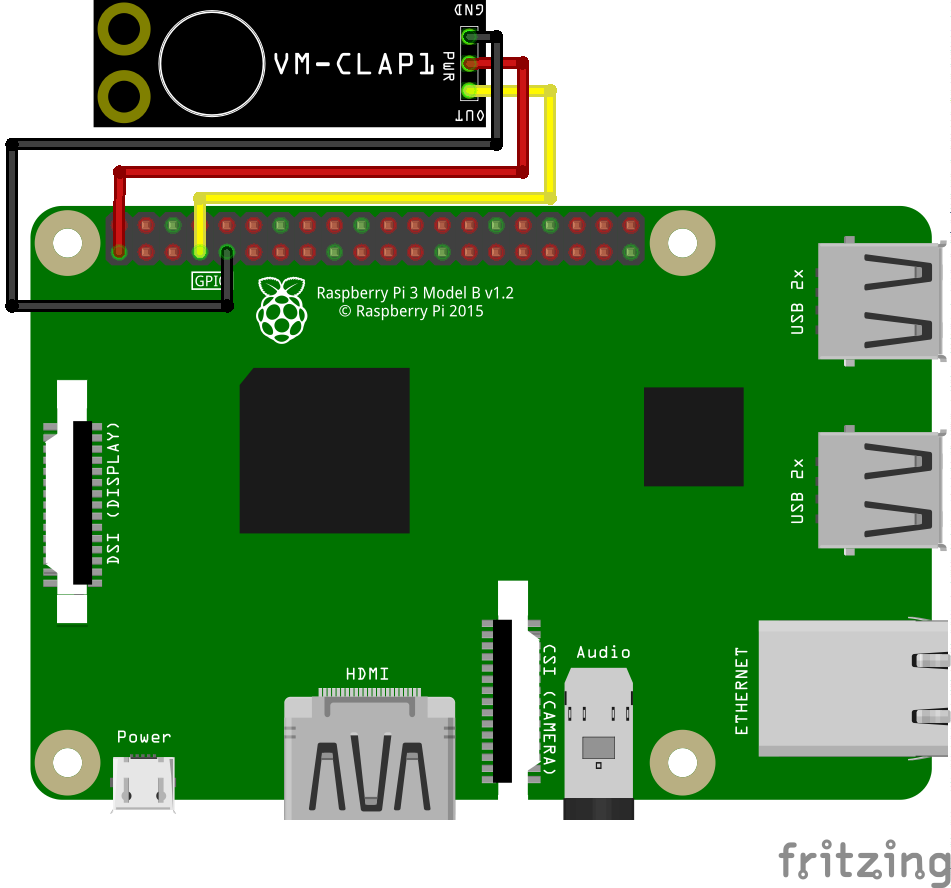
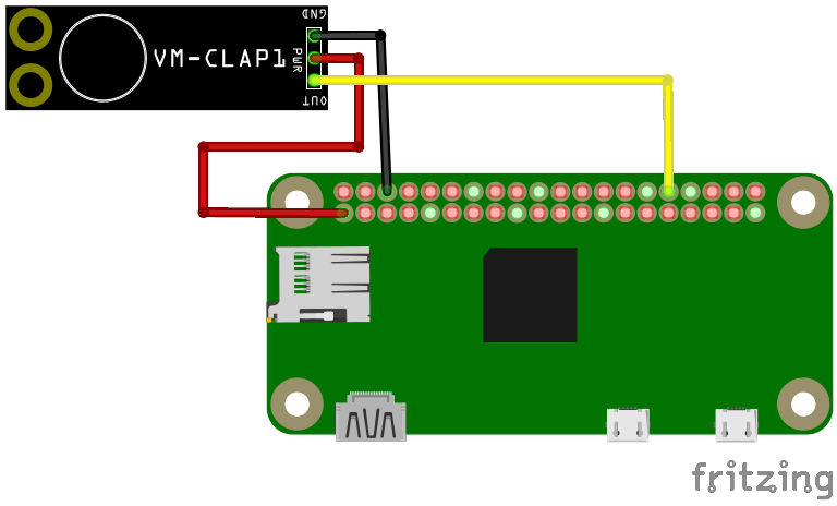
40-pin GPIO connector (B+, 2B, 3B, Zero)

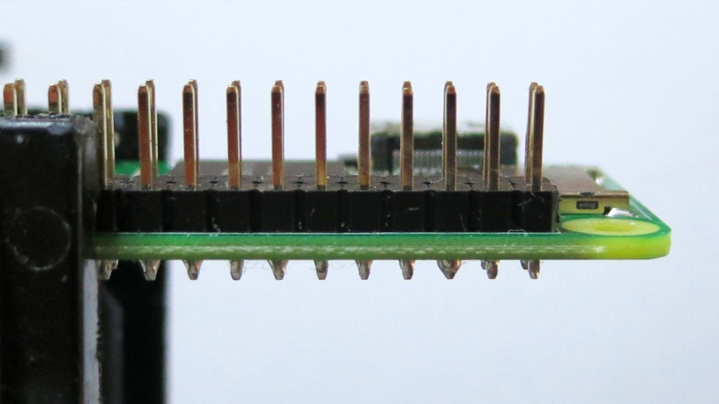
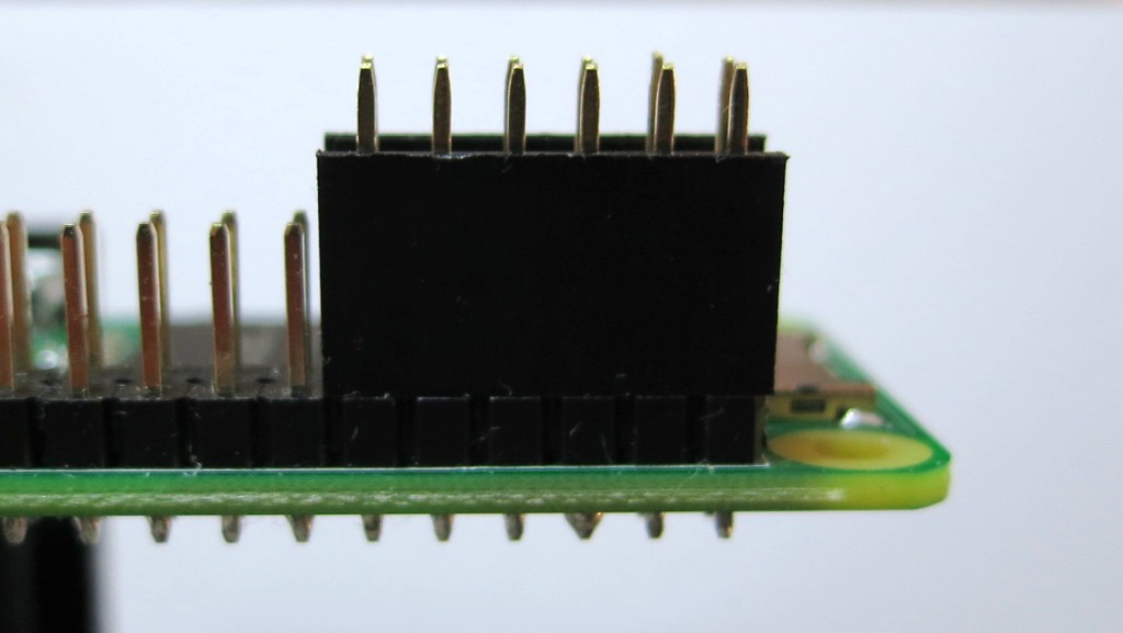
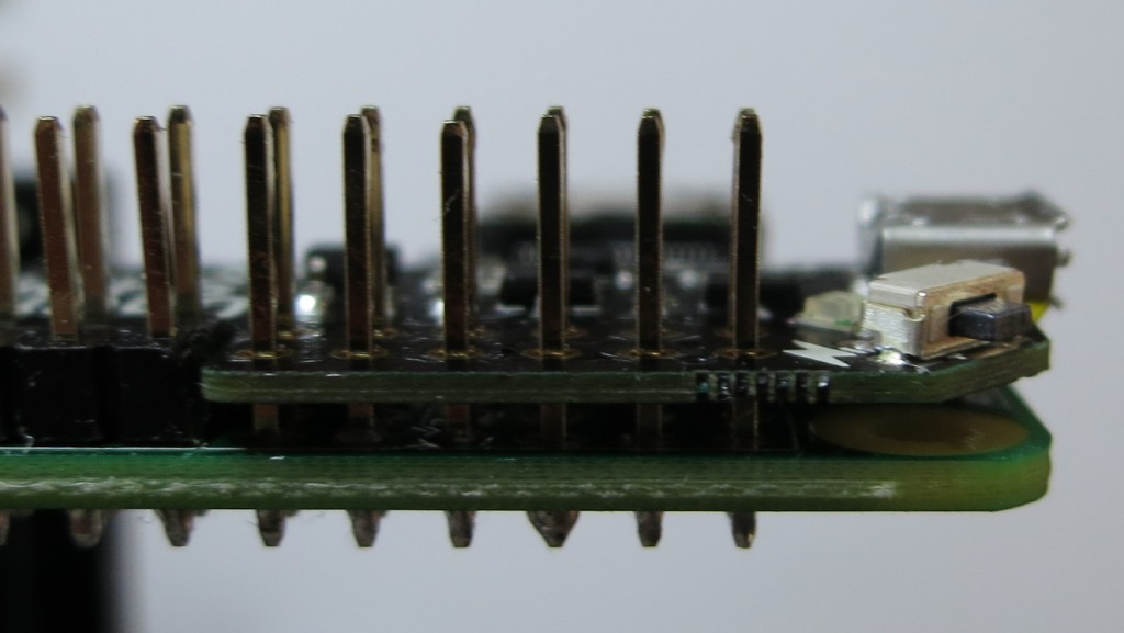
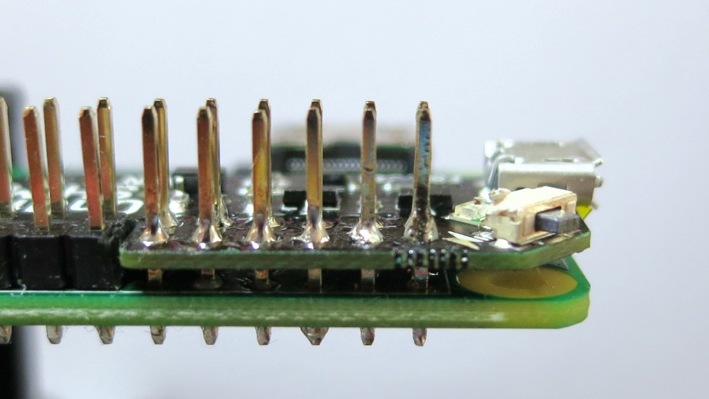
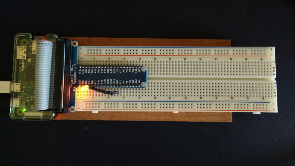
Connect the button between GPIO 27 and GND. If you use an ATX power button and a Raspberry Pi with a 40-pin GPIO header, connect it across the seventh column from the left:

            -
· · · · · ·|·|· · · · · · · · · · · · · 
· · · · · ·|·|· · · · · · · · · · · · · 
            -

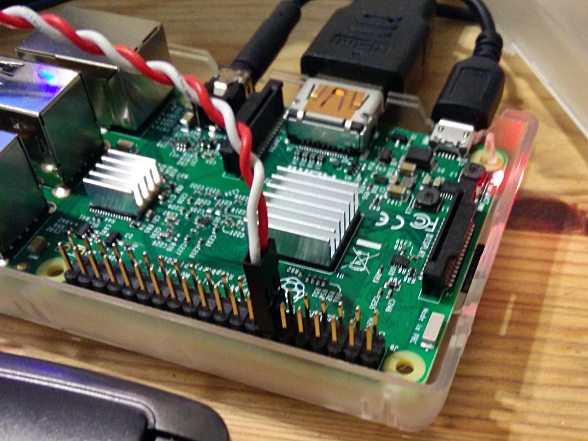
This shorts GPIO 27 (physical pin 13) to ground (physical pin 14) when the button is pressed.

26-pin GPIO connector (models B and A only)

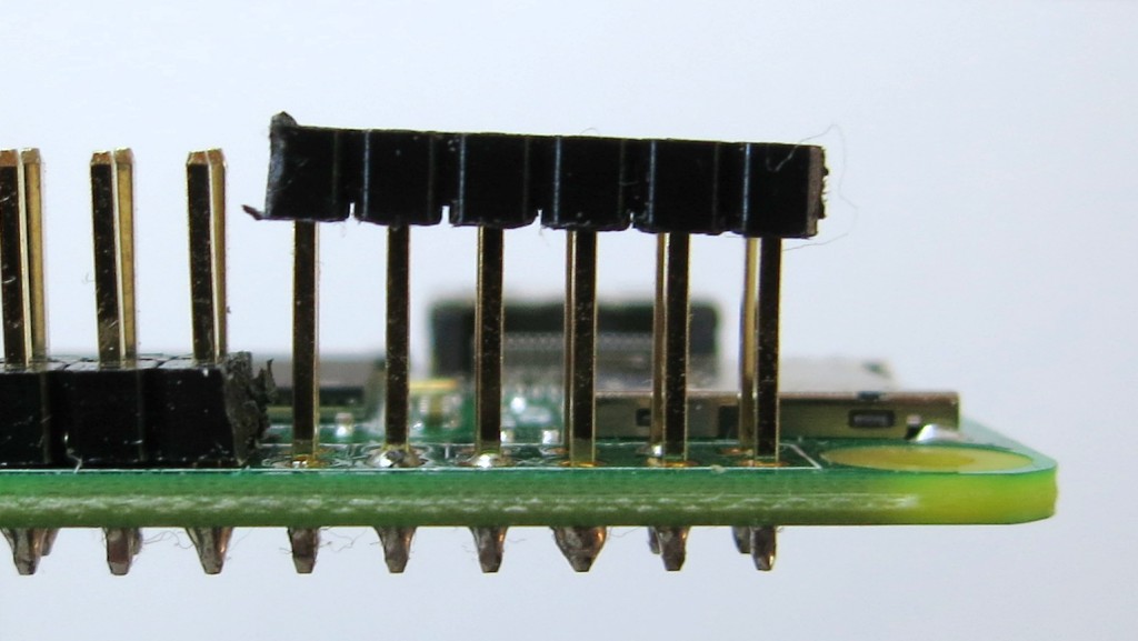
GPIO 27 is not exposed on the original Raspberry Pi header, so GPIO 17 is a reasonable option. If you use an ATX power button and a Raspberry Pi with a 26-pin GPIO header, connect it across the fifth and sixth columns of the second row:

 . . . . ._. . . . . . . .
 . . . .|. .|. . . . . . .
          -

You will also need to change line 7 of shutdown_button.py to read:

use_button=17

Software

Download the software first. I prefer to use

git clone https://github.com/scruss/shutdown_button.git

but you can download the zip file. If you do that, though, make sure to

unzip shutdown_button-master
cd shutdown_button-master

The software is installed with the following commands:

sudo apt install python3-gpiozero
sudo mkdir -p /usr/local/bin
chmod +x shutdown_button.py
sudo cp shutdown_button.py /usr/local/bin
sudo cp shutdown_button.service /etc/systemd/system
sudo systemctl enable shutdown_button.service
sudo systemctl start shutdown_button.service

Troubleshooting

Enabling the service should produce output very similar to:

Created symlink /etc/systemd/system/multi-user.target.wants/shutdown_button.service → /etc/systemd/system/shutdown_button.service.

You can check the status of the program at any time with the command:

systemctl status shutdown_button.service

This should produce output similar to:

● shutdown_button.service - GPIO shutdown button
   Loaded: loaded (/etc/systemd/system/shutdown_button.service; enabled; vendor 
   Active: active (running) since Sat 2017-10-21 11:20:56 EDT; 27s ago
 Main PID: 3157 (python3)
   CGroup: /system.slice/shutdown_button.service
           └─3157 /usr/bin/python3 /usr/local/bin/shutdown_button.py

Oct 21 11:20:56 naan systemd[1]: Started GPIO shutdown button.

If you’re seeing anything other than Active: active (running), it’s not working. Does the Python script have the right permissions? Is it in the right place? If you modified the script, did you check it for syntax errors?

The output from dmesg will show you any error messages generated by the service.

Modifications

If you use a HAT/pHAT/Bonnet/etc. with your Raspberry Pi, check pinout.xyz to see if it uses BCM 27. If you do need to change the pin, best to pick one that doesn’t have a useful system service like serial I/O or SPI. If you’re using an ATX button with a two pin connector, make sure you choose a pin physically adjacent to a ground pin.

If you modify the timing, please ensure that you keep the shutdown button press duration longer than the reboot one. Otherwise you’ll only be able to shut down.

Notes

You should not need to reboot to enable the service. One machine of mine — a Raspberry Pi Zero running Raspbian Stretch — did need a reboot before the button worked.

The reboot code is based on the Shutdown button example from the GPIO Zero documentation.

This is not the only combined shutdown/reset button project to use GPIO Zero. gilyes/pi-shutdown also does so, but pre-dates the implementation of the various hold time functions in GPIO Zero.

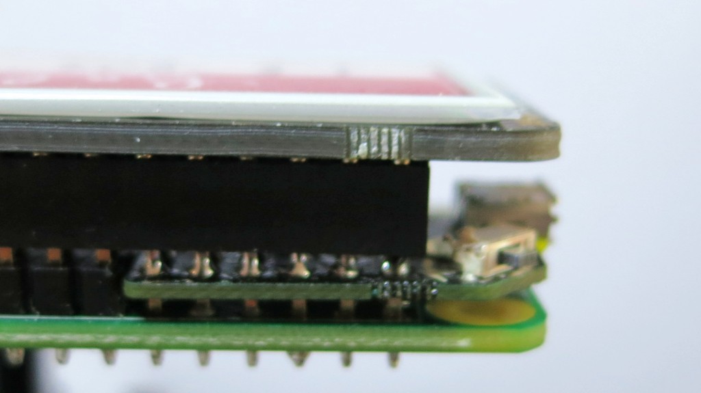
GPIO 27 was used, as it’s broken out onto a physical button on the Adafruit PiTFT+ display I own.

This is my first systemd service, and I’m still at the “amazed it works at all” stage. The service file may not contain the ideal configuration.
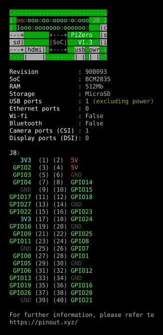
Connector Pinouts

From GPIO Zero’s pinout command

40 pin

   3V3  (1) (2)  5V    
 GPIO2  (3) (4)  5V    
 GPIO3  (5) (6)  GND   
 GPIO4  (7) (8)  GPIO14
   GND  (9) (10) GPIO15
GPIO17 (11) (12) GPIO18
GPIO27 (13) (14) GND   
GPIO22 (15) (16) GPIO23
   3V3 (17) (18) GPIO24
GPIO10 (19) (20) GND   
 GPIO9 (21) (22) GPIO25
GPIO11 (23) (24) GPIO8 
   GND (25) (26) GPIO7 
 GPIO0 (27) (28) GPIO1 
 GPIO5 (29) (30) GND   
 GPIO6 (31) (32) GPIO12
GPIO13 (33) (34) GND   
GPIO19 (35) (36) GPIO16
GPIO26 (37) (38) GPIO20
   GND (39) (40) GPIO21

26 pin

   3V3  (1) (2)  5V    
 GPIO0  (3) (4)  5V    
 GPIO1  (5) (6)  GND   
 GPIO4  (7) (8)  GPIO14
   GND  (9) (10) GPIO15
GPIO17 (11) (12) GPIO18
GPIO21 (13) (14) GND   
GPIO22 (15) (16) GPIO23
   3V3 (17) (18) GPIO24
GPIO10 (19) (20) GND   
 GPIO9 (21) (22) GPIO25
GPIO11 (23) (24) GPIO8 
   GND (25) (26) GPIO7 

Installing the Pimoroni OnOff Shim the hard way

Hey! This process permanently modifies your Raspberry Pi and may prevent it from working with many HATs and add-ons … It also has some really fiddly soldering. If in doubt, don’t.

Pimoroni’s OnOff SHIM adds what the Raspberry Pi should have had all along: a power button. While there are lots of soft power switches out there, the OnOff Shim adds circuitry to cut power to the Raspberry Pi after shutdown.

While the shim comes with a 12-socket header, that prevents you from using any other device that uses the leftmost GPIO pins. I wanted access to all the pins, and not have the shim create an unsightly bump on the pins. So this is what I did …

Regular GPIO header in place on a Raspberry Pi Zero W

Test-fit the socket header to mark where you’re going to cut the pin support block

Very carefully, cut the pin support block between (physical) pins 11-13 and 12-14. I used a mix of a sharp craft knife and nibbling with fine diagonal cutters. Try not to bend the GPIO pins either as you cut the block or lever the block out of the way

Apply non-conductive tape to the back of the OnOff Shim. I used Kapton, but electrical/insulating tape will do. Just make sure you don’t block any of the GPIO holes

Test-fit the shim. You may have to pare away at the support block a bit to get it to fit level with the rest of the pins

Now solder the shim in place. You want the solder joints as small as possible. I used extra liquid flux and very fine silver solder to just fill the pin holes. Too much solder left on the pins will stop HATs and socket headers fitting, so you may have to desolder as I had to do on the rightmost pin

Example HAT fitted with OnOff shim underneath. Note that his particular HAT — the Pimoroni Inky pHAT — will not work with this shim.

The OnOff SHIM uses GPIO pin BCM 17 (physical pin 11) as the power button sensor and BCM 4 as the power off signal. Any device that also uses BCM 17 (and possibly BCM 4) will likely cause the reset process to be triggered. This means that I can’t use the shim with my Inky pHAT EPD. You would have thought that Pimoroni might’ve considered that, since they made both. Consulting pinout.xyz suggests that 41 boards that likely may not work with the OnOff shim: Cirrus Logic Audio Card, Display-o-Tron 3000, DOTs, Enviro pHAT, ESP IoT pHAT, Explorer HAT, Explorer HAT Pro, Flex, GertVGA 666, High-Precision AD/DA Board, Hyperpixel, Inky pHAT, IoT pHAT, LEDBorg, MotoZero, Navio2 Autopilot, PaPiRus HAT, PaPiRus Zero, Piano HAT, Pibrella, Picade HAT, Pi Cap, PiGRRL Gamepad, Pi-LITE-r, Pi-mote, Pi PoE Switch HAT, PiStep2 Dual, PiStep2 Quad, Pi Stop, Propeller HAT, RoboHat, RTK Motor Controller, Servo PWM Pi Zero, Skywriter HAT, Ultimate GPS HAT, Voice HAT, Witty Pi, Witty Pi 2, Zero2Go, Zero LiPo and ZeroSeg.

While I like the OnOff SHIM, check carefully that it will work with your application.

Installing the Versatile Commodore Emulator (VICE) on Raspberry Pi

Updated 2020-11-28: thanks, Ennio! Should now build after new Raspberry Pi OS and Vice changes

As requested on our local Commodore user group mailing list, how to install VICE on a Raspberry Pi running Raspberry Pi OS:

sudo apt install autoconf automake build-essential byacc dos2unix flex libavcodec-dev libavformat-dev libgtk2.0-cil-dev libgtkglext1-dev libmp3lame-dev libmpg123-dev libpcap-dev libpulse-dev libreadline-dev libswscale-dev libvte-dev libxaw7-dev subversion yasm libgtk3.0-cil-dev xa65 libsdl2-dev libsdl2-image-dev libgtk-3-dev libglew-dev

mkdir -p src

cd src

svn checkout https://svn.code.sf.net/p/vice-emu/code/trunk trunk

cd trunk/vice

./autogen.sh

./configure --disable-pdf-docs

make -j4

sudo make install

This was freely adapted from the build docs, Linux-Native-Howto.txt, which has more info if you get stuck.


If you’re feeling fancy and want nice GUI controls and sound recording and menu stuff, try

./configure --disable-pdf-docs  --enable-lame --with-mpg123 --enable-shared-ffmpeg --enable-x64 --enable-native-gtk3ui --enable-desktop-files

This will give you desktop icons too. I’m not sure in the apt line is quite right, though — but I’ve had my doubts about all those CIL entries, ‘cos I think they pull in Mono/.Net, and who would want to use that?

gpiozero is rather good

gpiozero (‘A simple interface to GPIO devices with Raspberry Pi’) continues to impress me. One of its newer features is a pinout guide, accessed by the pinout command:

Raspberry Pi Zero pinout – click through for PDF

I’m trying to resist running it on every generation of Raspberry Pi that I have (B, A, 2B, 3B, Zero, Zero W) just for these pretty displays.

(ANSI console colours captured using script, then fed through ansi2html [from the Ubuntu colorized-logs package], printed to PDF from Firefox then mucked about a bit with in Inkscape)

inky phat draws a design

A bit dusty, and no sound, but worked out pretty well. (YouTube link if embed doesn’t work — inky phat draws a design)

Tiling based on plate 43, “a rotating motif …”, Wilson, Eva. Islamic designs for artists and craftspeople. New York: Dover Publications, 1988. ISBN: 978-0-486-25819-5

two-colour EPD displays are so pretty …

rotating tile pattern on Pimoroni Inky pHAT EPD display

This is a 600 dpi scan of a Pimoroni Inky pHAT EPD display. EPDs — electrophoretic displays, aka ‘e-ink’ or ‘e-paper’ — retain their image when turned off, so this Raspberry Pi had no power when I scanned it.

The image I made to fit the display is really small —

It’s a bit of a process making the images with just the right palette in GIMP, but I’m pleased how it turned out. I’d like to be able to write the vector images directly to the screen from SVG, but that might take some time.

InkyPhat-rotating2-212x104-web.svg
Tiling based on plate 43, “a rotating motif …”, Wilson, Eva. Islamic designs for artists and craftspeople. New York: Dover Publications, 1988. ISBN: 978-0-486-25819-5

Easy Raspberry Pi framebuffer screenshots with raspi2png

I gave a talk about retro-gaming on the Raspberry Pi yesterday. I was describing RetroPie, and I really needed lots of screenshots to illustrate games. I’m used to grabbing screens under X, but RetroPie runs without it, so all my usual tools were of no use.

I’d just found out about raspi2png, and it works really well! Usage is simple: just call it like

raspi2png -p outfile.png

and it’ll save whatever’s on the screen. It doesn’t play well with X, but there are already tools to take screenshots with that. As I was playing games, I didn’t want to have to pause the computer to take a shot, so I ran the command every five seconds for 30*5 seconds like this:

for f in {1..30}; do raspi2png -p retro_$(date -Iseconds).png; sleep 5; done

Here are some quality shots via raspi2png from Deathchase, officially the best ZX Spectrum game ever:

VM-CLAP1 👏 sensor + gpiozero on Raspberry Pi

Well, that was easy!

Since the Verbal Machines VM-CLAP1 sensor is an open collector type — that is, it sinks current when triggered — it behaves like a simple button to gpiozero, the Raspberry Pi Python GPIO library. If you attach a callback function to the sensor’s when_pressed event, your Python script will call that function every time it registers a clap.

The wiring is as simple as it could be:

 VM-CLAP1: Raspberry Pi:
 ========= =============
      GND → GND
      PWR → 3V3
      OUT → GPIO 4

This example code just prints clap! when the board picks up a 👏:

#!/usr/bin/env python3
# -*- coding: utf-8 -*-

# Raspberry Pi gpiozero test for
# Verbal Machines VM-CLAP1 clap sensor
#   scruss - 2017-06
#
# Wiring:
#
#  VM-CLAP1:    Raspberry Pi:
#  =========    =============
#    GND     →   GND
#    PWR     →   3V3
#    OUT     →   GPIO 4

from gpiozero import Button
from signal import pause

def clapping():
        print("clap!")

clap = Button(4)
clap.when_pressed = clapping
pause()

This is a trivial example, but at least it shows that anything you can do with a button, you can also do with this hand-clap sensor.

Clap Sensor part for Fritzing

I have no idea if this wiring would work, but it’s pretty …

For work, I blogged about Verbal MachinesHand Clap Sensor VM-CLAP1 (“Clap on 👏👏, Clap off 👏👏 – Elmwood Electronics”). I’ve made a preliminary part for Fritzing for the board: VM-CLAP1 Clap Sensor for Fritzing.zip

It should work in Breadboard and Schematic mode, but absolutely doesn’t work in PCB mode. This shouldn’t be a problem, as it’s only available as a standalone board. Fritzing doesn’t have any way to create new parts from scratch any more, so I had to base it on a somewhat similar-looking board, the SparkFun Electret Microphone Breakout.

I’m looking forward to see what I can do with gpiozero and the clap sensor.

Headless Raspberry Pi + VNC: useful resolution

Breadboards of Canada …

I just set up a Raspberry Pi Zero to be a little breadboard computer. Running a headless machine only through SSH gets a bit dull at times, so the inclusion of VNC Connect in Raspbian is handy.

Only problem was that the default screen size — something like 720×480 — was too small for most dialogue windows. Here’s how to enable a more useful resolution of 1024 × 768.

All of these are enabled from the raspi-config tool, so open a terminal and start it with:

sudo raspi-config

Enable Boot to Desktop

Select 3 Boot Options → B1 Desktop / CLI → B4 Desktop Autologin:


Enable VNC on Startup

Select 5 Interfacing Options → P3 VNC, and answer Yes to Would you like the VNC Server to be enabled?:


Set Screen Resolution

Select 7 Advanced Options → A5 Resolution → DMT Mode 16 (1024×768) …:


Once you’ve enabled all of these, raspi-config will ask if you wish to reboot your Raspberry Pi. Once it has rebooted, you should have a usable remote desktop.

(All of the above screenshots were taken from a headless Raspberry Pi Zero via VNC.)

Before & After

These were taken later on a Raspberry Pi 2 I’m setting up for a maker festival booth:

decidedly smol: 720×480

fix it to 1024×768 …

so much better!

The Pocket DEC Pretender (PDP) Zero

PDP (Pocket DEC Pretender) Zero: lettering came out a bit more, um,  artisanal than I’d hoped …

Digital (aka DEC) used to make some very solid minicomputers back when a minicomputer was fridge-sized and people were still building nuclear power stations to be controlled by them. The Raspberry Pi Zero is a very mini computer indeed, and in USB gadget mode running SimH it makes a nice little emulation platform.

The case is from Thingiverse: One Piece Raspberry Pi Zero + Camera Case (with GPIO) by Superrei, but with the DEC PDP logo in relief on the top.

DEC minis were famous for their arrays of blinkenlights. The Pocket DEC Pretender, not so much: it has one tiny green light that flickers a bit now and again:

PDP (Pocket DEC Pretender) Zero: case open, very few blinkenlights

But it’s a genuinely useful (for my values of useful) emulation platform. Here it is pretending to be a PDP-8, running BASIC under OS-8:

PDP (Pocket DEC Pretender) Zero: PDP-8 BASIC!

(background in case pictures woven in Toronto by Deftly Weft)

Apple II on Raspberry Pi

C’mon let’s all die of dysentery on the Oregon Trail!

Update: You probably want to use https://github.com/linappleii/linapple instead of Linapple-Pie these days.

Building and installing the linapple-pie Apple IIe emulator is relatively easy on the Raspberry Pi:

sudo apt install libcurl4-openssl-dev libzip-dev zlib1g-dev libsdl1.2-dev libsdl-gfx1.2-dev libsdl-image1.2-dev libsdl-sound1.2-dev build-essential git
git clone https://github.com/dabonetn/linapple-pie.git
cd linapple-pie/src
make
sudo make install

This also works on an x86_64 Ubuntu machine. It does also install on a PocketCHIP (even if it takes a really long time) but I can’t get the display resolution to fit correctly.

Raspberry Pi Zero: avoiding random network addresses in Gadget Mode

The Raspberry Pi Zero can be set up to appear as one of several USB OTG “gadgets” if you plug it into another computer. The most popular setting seems to be the virtual network gadget that turns your Zero into a computer on the end of your USB cable. Andrew Mulholland’s guide Raspberry Pi Zero – Programming over USB! (Part 2) (along with his super-short simple guide) seems to be the definitive source on how to set these modes up.

One problem, though, is that the Zero would show up on different network addresses every time it was restarted. The changing addresses made ssh access no fun at all. A suggestion on the Raspberry Pi forum helped me come up with a solution. On the Raspberry Pi Zero, run this command once:

echo 'options g_ether host_addr='$(dmesg | awk '/: HOST MAC/{print $NF}')' dev_addr='$(dmesg | awk '/: MAC/{print $NF}') | sudo tee /etc/modprobe.d/g_ether.conf

This will set the USB port’s hardware addresses to a fixed value, and you should always get a connection on the same IP address if it’s available.

How my Raspberry Pi Zero appears on my Ubuntu machine

Update: For some reason, this seemed to stop working, and I was getting the old random addresses again. I was resisting putting more stuff in /boot/cmdline.txt, but it seems to me it’s more reliable than what I proposed. So if your g_ether.conf looked like:

options g_ether host_addr=66:e0:94:40:44:74 dev_addr=de:82:66:79:e2:66

right at the end of your /boot/cmdline.txt (which is all one line, btw), add

 g_ether.host_addr=66:e0:94:40:44:74 g_ether.dev_addr=de:82:66:79:e2:66

You’ll probably also want to share the IPv4 connection so your Raspberry Pi Zero can use the network of the device it’s attached to:

Emulating a Mac IIx on Raspberry Pi

Yup, I have a failing for 512×384 screens …

Running Mini vMac on a Raspberry Pi is hardly news. But maybe running it as a colour Mac II is. The screen size I’ve chosen is closer to a Color Classic, for no other reason that I like it.

To build a Mac II-capable version of Mini vMac, you’ll need the Alpha source code. You’ll also need a working Mini vMac setup, as it uses a 68k Mac program to set up the source. Pretty much any basic setup and bootable disk will run this okay:

Mini vMac building on an emulated Mac Classic booting from the System 7 Network Access floppy image (no, I couldn’t boot from Classic’s hidden boot ROM disk)

The build options I chose are:

-t larm -ccs -m II -hres 512 -vres 384 -depth 3 -mf 2 -magnify 1 -em-cpu 2 -mem 8M

I’ve chosen to swap the Ctrl key with the Command (⌘) key, as most non-Mac keyboards work better with this.

The build program will export a file out/minivmac-3.5.0-larm.tar that you can unpack into the full source code. It’s a really simple build, and fast, too.

Now you’ll need a Mac IIx ROM image (which I’m not supposed to help you find, but it’s an easy search) and OS image disks from the Mini vMac System Software page. Have fun!

making an hourly chime with cron

I wanted to have a “Hey, be here now!” ping throughout the working day. Something loud enough to hear, but not irritating.

Doing this with cron was harder than you might expect. It seems that sound is typically part of the X11 display infrastructure, so you need to give the command permission to make a noise on this particular machine’s display. Here’s the crontab line I came up with:

# m h    dom mon dow   command
  0 9-17 *   *   1-5   export DISPLAY=:0 && /usr/bin/play -q /home/scruss/sounds/ting/ting.wav

That translates as: at 0 minutes past the hours of 09:00 to 17:00 on any weekday (day of week = 1-5, and we don’t care about day of month or which month it is), execute the command play (part of the sox package) with no text output (-q). cron needs environment variables like DISPLAY set, and prefers full command paths. It may trigger a second or so after the turn of the hour; this is good enough for me.

As for the alert, I wanted something distinctive — percussive, short, bright — but with a tiny bit of modulation to stop it sounding like a bland computer-generated sine wave. This is what I made; click on the image and the sound should play or download:

ting-audacityIt’s essentially a 2093 Hz (C7) sine wave, mixed with itself frequency-modulated at 7 Hz. Why 7 Hz? Apart from sounding about right, 2093 is exactly divisible by 7, 13 & 23, so I used a factor for neatness.

There was some later messing about in Audacity (mostly fades and length edits; I forget exactly what). The two components were generated using sox:

sox -n ting-plain.wav synth 1 sine C7 fade l 0 1 1
 sox -n ting-vibrato.wav synth 1 sin C7 synth 1 sine fmod 7 fade l 0 1 1

Yes, sox does have pretty horrible syntax, doesn’t it?

The frequency-modulated one seems to be pretty close to the final result. It would be less time spent trying to save time …

micro, a nice little text editor

screenshot-from-2016-09-18-15-24-13

micro – https://github.com/zyedidia/micro – is a terminal-based text editor. Unlike vi, emacs and nano, it has sensible default command keys: Ctrl+S saves, Ctrl+Q quits, Ctrl+X/C/V cuts/copies/pastes, etc. micro also supports full mouse control (even over ssh), Unicode and colour syntax highlighting.

micro is written in Go – https://golang.org – so is very easy to install:

go get -u github.com/zyedidia/micro/...

If you don’t already have Go installed, it’s pretty simple, even on a Raspberry Pi: https://golang.org/doc/install

If your running under Linux, you probably want to have xclip installed for better cut/paste support.

Overall, I really like micro. It’s much easier to use than any of the standard Linux text editors. It uses key commands that most people expect. Creating code should not be made harder than it needs to be.

(I was about to suggest FTE, as it appears to be the closest thing to the old MS-DOS 6 editor that I’ve seen under Linux. While it’s a great plain text editor, its Unicode support isn’t where it needs to be in 2016.
micro suggestion came via MetaFilter’s Ctrl + Q to quit. Need I say more?
)