In early 2013, I must’ve been left unsupervised for too long since I made The Quite Rubbish Clock:
It still isn’t human readable …
Written in (Owen Wilson voice) kind of an obsolete vernacular and running on hardware that’s now best described as “quaint”, it was still absurdly popular at the time. Raspberry Pis were still pretty new, and people were looking for different things to do with them.
I happened across the JASchilz/uQR: QR Code Generator for MicroPython the other day, and remembered I had some tiny OLED screens that were about the same resolution as the old Nokia I’d used in 2013. I wondered: could I …?
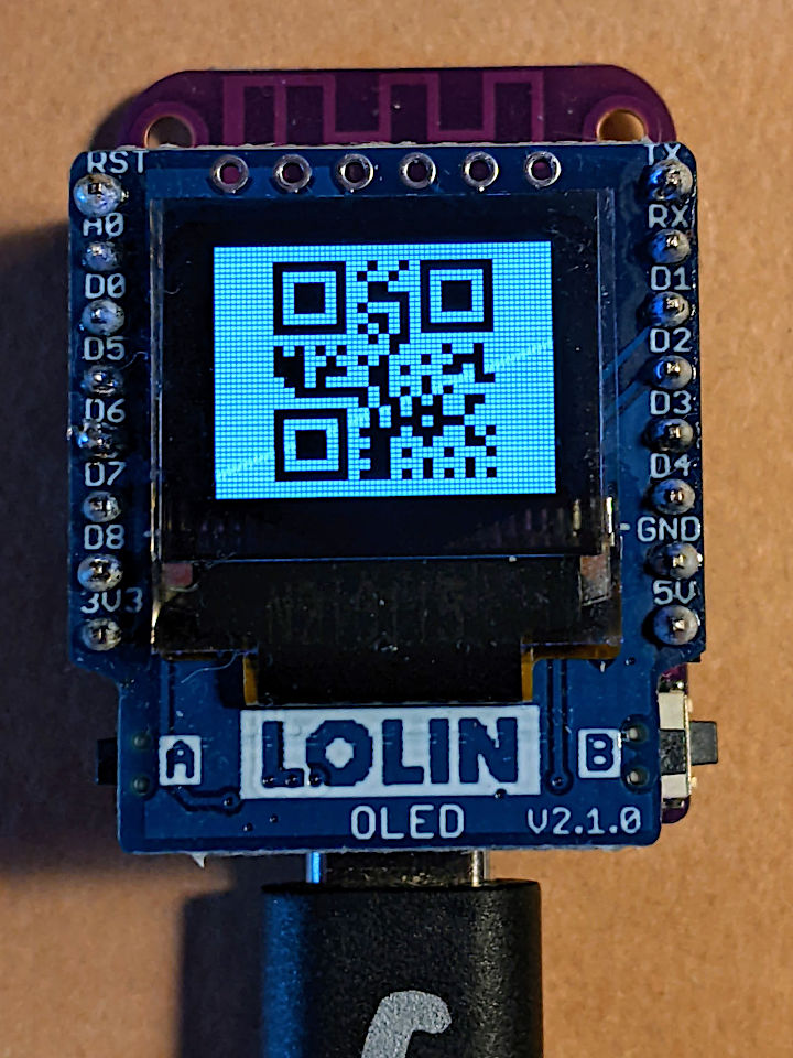
OLED Shield on a LOLIN S2 Mini: very smol indeed
The board is a LOLIN S2 Mini with a OLED 0.66 Inch Shield on top, all running MicroPython. One limitation I found in the MicroPython QR library was that it was very picky about input formats, so it only displays the time as HHMMSS with no separators.
Source, of course:
# -*- coding: utf-8 -*-
# yes, the Quite Rubbish Clock rides again ...
# scruss, 2022-06-30
# MicroPython on Lolin S2 Mini with 64 x 48 OLED display
# uses uQR from https://github.com/JASchilz/uQR
# - which has problems detecting times with colons

from machine import Pin, I2C, RTC
import s2mini  # on Lolin ESP32-S2 Mini
import ssd1306
from uQR import QRCode

WIDTH = 64  # screen size
HEIGHT = 48
SIZE = 8  # text size
r = RTC()

# set up and clear screen
i2c = I2C(0, scl=Pin(s2mini.I2C_SCL), sda=Pin(s2mini.I2C_SDA))
oled = ssd1306.SSD1306_I2C(WIDTH, HEIGHT, i2c)
oled.fill(0)


def snazz():
    marquee = [
        "   **",
        "   **",
        "   **",
        "   **",
        "   **",
        "********",
        " ******",
        "  ****",
        "   **",
        " quite",
        "rubbish",
        " clock",
        "  mk.2",
        "<scruss>",
        " >2022<"
    ]
    for s in marquee:
        oled.scroll(0, -SIZE)  # scroll up one text line
        oled.fill_rect(0, HEIGHT-SIZE, WIDTH,
                       SIZE, 0)  # blank last line
        oled.text("%-8s" % s, 0, HEIGHT-SIZE)  # write text
        oled.show()
        time.sleep(0.25)
    time.sleep(5)
    oled.fill(1)
    oled.show()


snazz()  # tedious crowd-pleasing intro

qr = QRCode()
while True:
    qr.add_data("%02d%02d%02d" % r.datetime()[4:7])
    qr.border = 1  # default border too big to fit small screen
    m = qr.get_matrix()
    oled.fill(1)
    for y in range(len(m)):
        for x in range(len(m[0])):
            # plot a double-sized QR code, centred, inverted
            oled.fill_rect(9 + 2*x, 1 + 2*y, 2, 2, not m[y][x])
    oled.show()
    time.sleep(0.05)
    qr.clear()
If your output is glitchy, you might need to put the following in boot.py:
import machine
machine.freq(240000000)
This increases the ESP32-S2’s frequency from 160 to 240 MHz.
Update: Eep! This post was featured on the Raspberry Pi blog today. Thanks, Liz!
And now for something completely different:
… a clock that isn’t human readable. You’ll need a QR code reader to be able to tell the time.
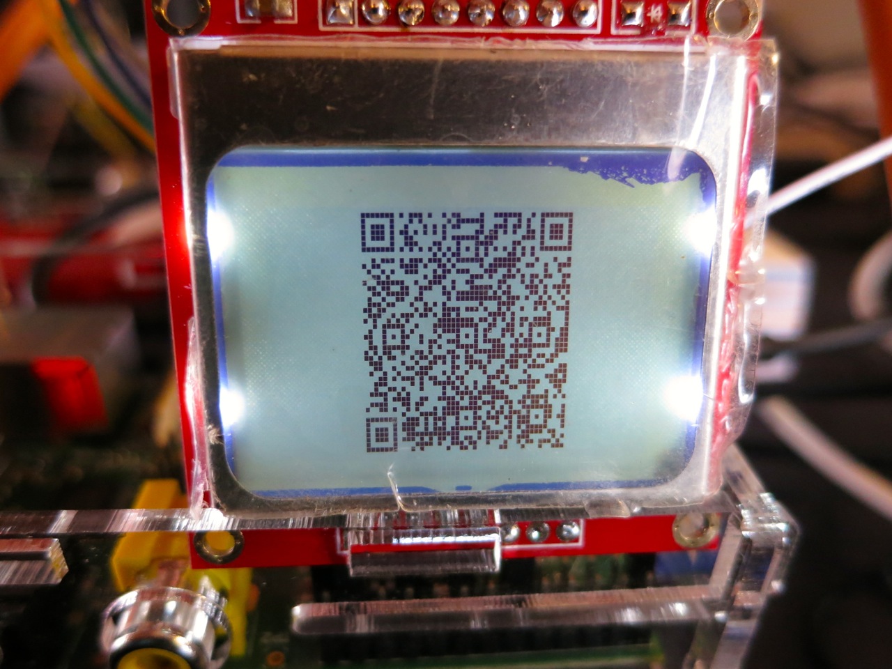
This, however, is not the prime purpose of the exercise. I was looking for an excuse to try some direct hardware projects with the GPIO, and I remembered I had a couple of Nokia-style surplus LCDs lying about that could be pressed into service. These LCDs aren’t great: 84×48 pixels, 3V3 logic, driven by SPI via an 8-pin header which includes PWM-controllable LED backlighting. They are cheap, and available almost everywhere: DealExtreme ($5.36), SparkFun ($9.95), Adafruit ($10, but includes a level shifter, which you really need if you’re using a 5V logic Arduino), Solarbotics ($10) and Creatron (about $12; but you can walk right in and buy one). Despite being quite difficult to use, helpful people have written drivers to make these behave like tiny dot-addressable screens.
I’d been following the discussion on the Raspberry Pi forum about driving the Nokia LCD from a Raspberry Pi. Only when user bgreat posted some compact code that was supposed to run really fast did I dig out the LCD board and jumper wires. Building on bgreat’s nokiaSPI.py class and a few other bits of code, here’s what I built to make this singularly pointless clock:
#!/usr/bin/python
# -*- coding: utf-8 -*-
# qrclock - The Quite Rubbish Clock for Raspberry Pi - scruss, 2013-01-19
import time
# need to use git://github.com/mozillazg/python-qrcode.git
import qrcode
from PIL import Image
import ImageOps
# uses bgreat's SPI code; see
# raspberrypi.org/phpBB3/viewtopic.php?f=32&amp;amp;amp;t=9814&amp;amp;amp;p=262274&amp;amp;amp;hilit=nokia#p261925
import nokiaSPI
noki = nokiaSPI.NokiaSPI() # create display device
qr = qrcode.QRCode(version=1, # V.1 QR Code: 21x21 px
error_correction=qrcode.constants.ERROR_CORRECT_M,
box_size=2, border=1)
bg = Image.new('1', (84, 48)) # blank (black) image background
while 1:
qr.clear()
newbg = bg.copy() # copy blank background
s = time.strftime('%Y-%m-%d %H:%M:%S')
qr.add_data(s) # make QR Code of YYYY-MM-DD HH:MM:SS
qr.make()
qrim = qr.make_image() # convert qrcode object to PIL image
qrim = qrim.convert('L') # make greyscale
qrim = ImageOps.invert(qrim) # invert colours: B-&amp;amp;gt;W and W-&amp;amp;gt;B
qrim = qrim.convert('1') # convert back to 1-bit
newbg.paste(qrim, (18, 0)) # paste QR Code into blank background
noki.show_image(newbg) # display code on LCD
time.sleep(0.4) # pause before next display
(Convenient archive of all the source: qrclock2.zip, really including bgreat’s nokiaSPI class this time …)
To get all this working on your Raspberry Pi, there’s a fair amount of configuration. The best references are bgreat’s own comments in the thread, but I’ve tried to include everything here.
Enabling the SPI kernel module
As root, edit the kernel module blacklist file:
sudo vi /etc/modprobe.d/raspi-blacklist.conf
Comment out the spi-bcm2708 line so it looks like this:
#blacklist spi-bcm2708
Save the file so that the module will load on future reboots. To enable the module now, enter:
sudo modprobe spi-bcm2708
Now, if you run the lsmod command, you should see something like:
Module                  Size  Used by
spi_bcm2708             4421  0
Installing the WiringPi, SPI and other required packages
WiringPi by Gordon is one of the neater Raspberry Pi-specific modules, as it allows relatively easy access to the Raspberry Pi’s GPIO pins. For Raspbian, there are a few other imaging libraries and package management tools you’ll need to install here:
Finding a library that provided all the right functions was the hardest part here. I ended up using mozillazg‘s fork of lincolnloop‘s python-qrcode module. mozillazg’s fork lets you use most of the lovely PIL methods, while the original hides most of them. Since I had to do some image compositing and colour remapping to make the image appear correct on the Nokia screen, the new fork was very helpful.
To install it:
git clone git://github.com/mozillazg/python-qrcode.git
cd python-qrcode/
sudo python ./setup.py install
The tiny 84×48 resolution of the Nokia screen doesn’t give you many options for sizing QR codes. For the time display of the clock, a 21×21 module Version 1 code with two pixels per module and one module margin just fits into 48 pixels. Using a medium level of error correction, you can fit the 19-character message (such as “2013-01-19 18:56:59”) into this tiny screen with a very good chance of it being read by any QR code reader.
(In the video, there’s a much larger QR code that’s a link to this blog post. That’s a Version 7 code [45×45 modules] at one pixel per module and no margin. This doesn’t meet Denso Wave’s readability guidelines, but the Nokia screen has large blank margins which seem to help. It won’t read on every phone, but you’re here at this link now, so you don’t need it …)
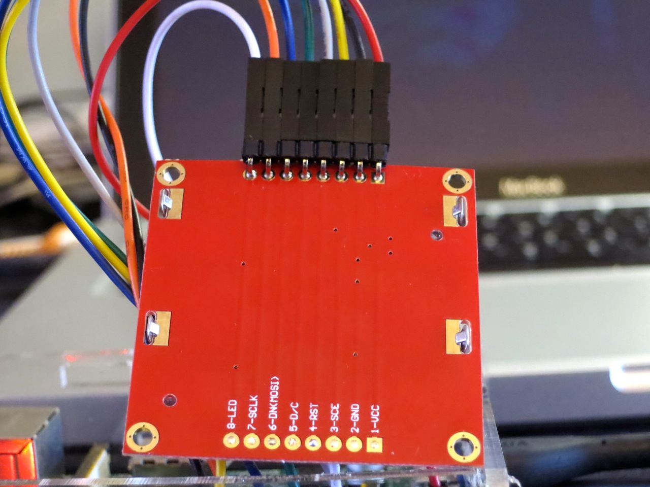
Wiring it all up
(Do I really need to say that you’ll be messing around with the inner delicate bits of your Raspberry Pi here, and if you do something wrong, you could end up with a dead Raspberry Pi? No? Okay. Just make sure you take some static precautions and you really should have the thing shut down and powered off.)
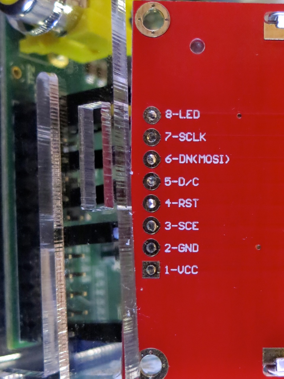
You’ll need 8 female-female right-angled ones). Note that the thick border of the LCD is the top of the screen. These boards are made who-knows-where by who-knows-whom, and there’s a hugevariety of labels and layouts on the pins. My one appears to be yet another variant, and is labelled:
VCC
GND
SCE
RST
D/C
DNK(MOSI)
SCLK
LED
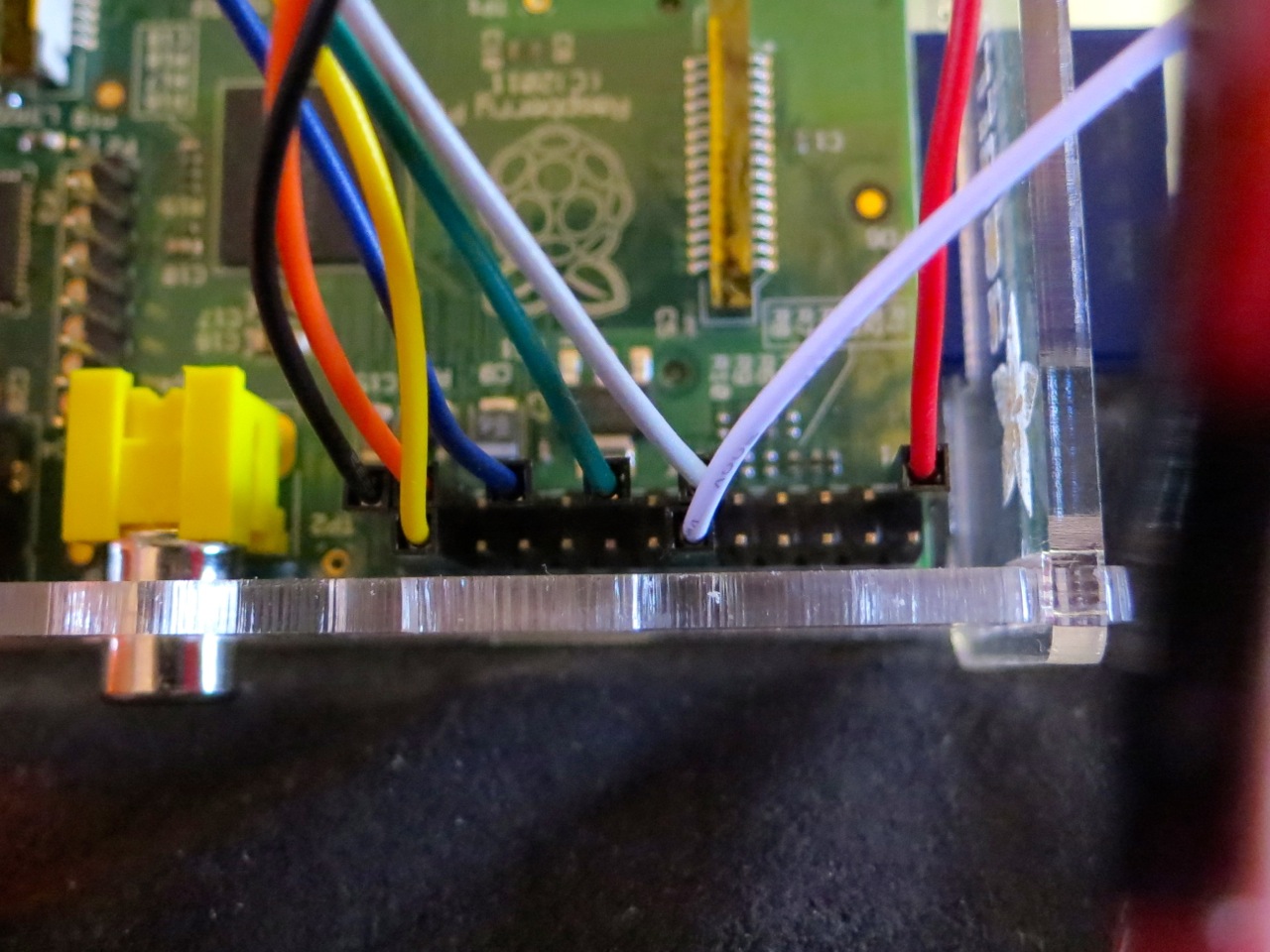
This is how I wired it (from comments in bgreat’s code and the GPIO reference):
 LCD Pin       Function      Pi GPIO Pin #   Pi Pin Name
============= ============= =============== =============
 1 VCC         Vcc            1              3.3 V
 2 GND         Ground        25              GND
 3 SCE         Chip Enable   24              GPIO08 SPI0_CE0_N
 4 RST         Reset         11              GPIO17
 5 D/C         Data/Command  15              GPIO22
 6 DNK(MOSI)   Data In       19              GPIO10 SPI0_MOSI
 7 SCLK        Serial Clock  23              GPIO11 SPI0_SCLK
 8 LED         Backlight     12              GPIO18 PWM0
Wire it up, and fire up the program:
sudo ./qrclock.py
Yes, code that accesses GPIO needs to be run as root. Pesky, but helps you avoid running code that accidentally scrams the nuclear power station you’re controlling from your Raspberry Pi …
One book put me off geography for ever, and it was called Find the Place. Each page had a map of the UK like this
Next to it, was the numbered list of places. What you were supposed to do was memorize the name and location, and then (with the list covered by the pupils) the teacher would go through the class by turn and you’d have to say the place name. “Find the Place”; clever, huh?
I’ve always been allergic to rote learning, and I never even tried to get these. I just remember trying to hide when that part of the lesson came round. I don’t think there was any theme to the places; they weren’t even the five main glove manufacturing towns in the Midlands, or anything. Just random dots.
To try your mad geog skillz, those dots are real places. Can you name them? Answers after the fold.