It’s mid-February in Toronto: -10 °C and snowy. The memory of chirping summer fields is dim. But in my heart there is always a cricket-loud meadow.
Short of moving somewhere warmer, I’m going to have to make my own midwinter crickets. I have micro-controllers and tiny speakers: how hard can this be?
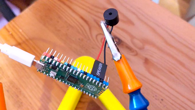
more fun than a bucket of simulated crickets (video description: a plastic box containing three USB power banks, each with USB cable leading to a Raspberry Pi Pico board. Each board has a small electromagnetic speaker attached between ground and a data pin)
I could have merely made these beep away at a fixed rate, but I know that real crickets tend to chirp faster as the day grows warmer. This relationship is frequently referred to as Dolbear’s law. The American inventor Amos Dolbear published his observation (without data or species identification) in The American Naturalist in 1897: The Cricket as a Thermometer —
pretty bold assertions there without data eh, Amos old son …?
When emulating crickets I’m less interested in the rate of chirps per minute, but rather in the period between chirps. I could also care entirely less about barbarian units, so I reformulated it in °C (t) and milliseconds (p):
t = ⅑ × (40 + 75000 ÷ p)
Since I know that the micro-controller has an internal temperature sensor, I’m particularly interested in the inverse relationship:
p = 15000 ÷ (9 * t ÷ 5 – 8)
I can check this against one of Dolbear’s observations for 70°F (= 21⅑ °C, or 190/9) and 120 chirps / minute (= 2 Hz, or a period of 500 ms):
Now I’ve got the timing worked out, how about the chirp sound. From a couple of recordings of cricket meadows I’ve made over the years, I observed:
The total duration of a chirp is about ⅛ s
A chirp is made up of four distinct events:
a quieter short tone;
a longer louder tone of a fractionally higher pitch;
the same longer louder tone repeated;
the first short tone repeated
There is a very short silence between each tone
Each cricket appears to chirp at roughly the same pitch: some slightly lower, some slightly higher
The pitch of the tones is in the range 4500–5000 Hz: around D8 on the music scale
I didn’t attempt to model the actual stridulating mechanism of a particular species of cricket. I made what sounded sort of right to me. Hey, if Amos Dolbear could make stuff up and get it accepted as a “law”, I can at least get away with pulse width modulation and tiny tinny speakers …
This is the profile I came up with:
21 ms of 4568 Hz at 25% duty cycle
7 ms of silence
28 ms of 4824 Hz at 50% duty cycle
7 ms of silence
28 ms of 4824 Hz at 50% duty cycle
7 ms of silence
21 ms of 4568 Hz at 25% duty cycle
7 ms of silence
That’s a total of 126 ms, or ⅛ish seconds. In the code I made each instance play at a randomly-selected relative pitch of ±200 Hz on the above numbers.
For the speaker, I have a bunch of cheap PC motherboard beepers. They have a Dupont header that spans four pins on a Raspberry Pi Pico header, so if you put one on the ground pin at pin 23, the output will be connected to pin 26, aka GPIO 20:
# cricket thermometer simulator - scruss, 2024-02
# uses a buzzer on GPIO 20 to make cricket(ish) noises
# MicroPython - for Raspberry Pi Pico
# -*- coding: utf-8 -*-

from machine import Pin, PWM, ADC, freq
from time import sleep_ms, ticks_ms, ticks_diff
from random import seed, randrange

freq(125000000)  # use default CPU freq
seed()  # start with a truly random seed
pwm_out = PWM(Pin(20), freq=10, duty_u16=0)  # can't do freq=0
led = Pin("LED", Pin.OUT)
sensor_temp = machine.ADC(4)  # adc channel for internal temperature
TOO_COLD = 10.0  # crickets don't chirp below 10 °C (allegedly)
temps = []  # for smoothing out temperature sensor noise
personal_freq_delta = randrange(400) - 199  # different pitch every time
chirp_data = [
    # cadence, duty_u16, freq
    # there is a cadence=1 silence after each of these
    [3, 16384, 4568 + personal_freq_delta],
    [4, 32768, 4824 + personal_freq_delta],
    [4, 32768, 4824 + personal_freq_delta],
    [3, 16384, 4568 + personal_freq_delta],
]
cadence_ms = 7  # length multiplier for playback


def chirp_period_ms(t_c):
    # for a given temperature t_c (in °C), returns the
    # estimated cricket chirp period in milliseconds.
    #
    # Based on
    # Dolbear, Amos (1897). "The cricket as a thermometer".
    #   The American Naturalist. 31 (371): 970–971. doi:10.1086/276739
    #
    # The inverse function is:
    #     t_c = (75000 / chirp_period_ms + 40) / 9
    return int(15000 / (9 * t_c / 5 - 8))


def internal_temperature(temp_adc):
    # see pico-micropython-examples / adc / temperature.py
    return (
        27
        - ((temp_adc.read_u16() * (3.3 / (65535))) - 0.706) / 0.001721
    )


def chirp(pwm_channel):
    for peep in chirp_data:
        pwm_channel.freq(peep[2])
        pwm_channel.duty_u16(peep[1])
        sleep_ms(cadence_ms * peep[0])
        # short silence
        pwm_channel.duty_u16(0)
        pwm_channel.freq(10)
        sleep_ms(cadence_ms)


led.value(0)  # led off at start; blinks if chirping
### Start: pause a random amount (less than 2 s) before starting
sleep_ms(randrange(2000))

while True:
    loop_start_ms = ticks_ms()
    sleep_ms(5)  # tiny delay to stop the main loop from thrashing
    temps.append(internal_temperature(sensor_temp))
    if len(temps) > 5:
        temps = temps[1:]
    avg_temp = sum(temps) / len(temps)
    if avg_temp >= TOO_COLD:
        led.value(1)
        loop_period_ms = chirp_period_ms(avg_temp)
        chirp(pwm_out)
        led.value(0)
        loop_elapsed_ms = ticks_diff(ticks_ms(), loop_start_ms)
        sleep_ms(loop_period_ms - loop_elapsed_ms)
There are a few more details in the code that I haven’t covered here:
The program pauses for a short random time on starting. This is to ensure that if you power up a bunch of these at the same time, they don’t start exactly synchronized
The Raspberry Pi Pico’s temperature sensor can be slightly noisy, so the chirping frequency is based on the average of (up to) the last five readings
There’s no chirping below 10 °C, because Amos Dolbear said so
The built-in LED also flashes if the board is chirping. It doesn’t mimic the speaker’s PWM cadence, though.
Before I show you the next video, I need to say: no real crickets were harmed in the making of this post. I took the bucket outside (roughly -5 °C) and the “crickets” stopped chirping as they cooled down. Don’t worry, they started back up chirping again when I took them inside.
“If You’re Cold They’re Cold, Bring Them Inside” (video description: a plastic box containing three USB power banks, each with USB cable leading to a Raspberry Pi Pico board. Each board has a small electromagnetic speaker attached between ground and a data pin)
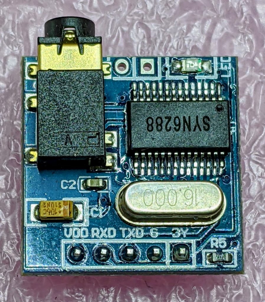
After remarkable success with the SYN-6988 TTS module, then somewhat less success with the SYN-6658 and other modules, I didn’t hold out much hope for the YuTone SYN-6288, which – while boasting a load of background tunes that could play over speech – can only convert Chinese text to speech
The wiring is similar to the SYN-6988: a serial UART connection at 9600 baud, plus a Busy (BY) line to signal when the chip is busy. The serial protocol is slightly more complicated, as the SYN-6288 requires a checksum byte at the end.
As I’m not interested in the text-to-speech output itself, here’s a MicroPython script to play all of the sounds:
# very crude MicroPython demo of SYN6288 TTS chip
# scruss, 2023-07
import machine
import time

### setup device
ser = machine.UART(
    0, baudrate=9600, bits=8, parity=None, stop=1
)  # tx=Pin(0), rx=Pin(1)

busyPin = machine.Pin(2, machine.Pin.IN, machine.Pin.PULL_UP)


def sendspeak(u2, data, busy):
    # modified from https://github.com/TPYBoard/TPYBoard_lib/
    # u2 = UART(uart, baud)
    eec = 0
    buf = [0xFD, 0x00, 0, 0x01, 0x01]
    # buf = [0xFD, 0x00, 0, 0x01, 0x79]  # plays with bg music 15
    buf[2] = len(data) + 3
    buf += list(bytearray(data, "utf-8"))
    for i in range(len(buf)):
        eec ^= int(buf[i])
    buf.append(eec)
    u2.write(bytearray(buf))
    while busy.value() != True:
        # wait for busy line to go high
        time.sleep_ms(5)
    while busy.value() == True:
        # wait for it to finish
        time.sleep_ms(5)


for s in "abcdefghijklmnopqrstuvwxy":
    playstr = "[v10][x1]sound" + s
    print(playstr)
    sendspeak(ser, playstr, busyPin)
    time.sleep(2)

for s in "abcdefgh":
    playstr = "[v10][x1]msg" + s
    print(playstr)
    sendspeak(ser, playstr, busyPin)
    time.sleep(2)

for s in "abcdefghijklmno":
    playstr = "[v10][x1]ring" + s
    print(playstr)
    sendspeak(ser, playstr, busyPin)
    time.sleep(2)
Each sound starts and stops with a very loud click, and the sound quality is not great. I couldn’t get a good recording of the sounds (some of which of which are over a minute long) as the only way I could get reliable audio output was through tiny headphones. Any recording came out hopelessly distorted:
I’m not too disappointed that this didn’t work well. I now know that the SYN-6988 is the good one to get. It also looks like I may never get to try the XFS5152CE speech synthesizer board: AliExpress has cancelled my shipment for no reason. It’s supposed to have some English TTS function, even if quite limited.
Here’s the auto-translated SYN-6288 manual, if you do end up finding a use for the thing
I have a bunch of other boards on order to see if the other chips (SYN6288, SYN6658, XF5152) work in the same way. I really wonder which I’ll end up receiving!
Update (2023-07-09): Got the SYN6658. It does not support English TTS and thus is not recommended. It does have some cool sounds, though.
Embedded Text Command Sound Table
The github repo references Embedded text commands, but all of the sound references was too difficult to paste into a table there. So here are all of the ones that the SYN-6988 knows about:
Name is the string you use to play the sound, eg: [x1]sound101
Alias is an alternative name by which you can call some of the sounds. This is for better compatibility with the SYN6288 apparently. So [x1]sound101 is exactly the same as specifying [x1]sounda
Type is the sound description from the manual. Many of these are blank
Link is a playable link for a recording of the sound.
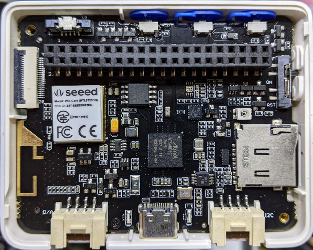
A while back, Seeed Studio sent me one of their Wio Terminal devices to review. It was pretty neat, but being limited to using Arduino to access all of it features was a little limiting. I still liked it, though, and wrote about it here: SeeedStudio Wio Terminal
Wio Terminal, doing a thing
There wasn’t any proper MicroPython support for the device as it used a MicroChip/Atmel SAMD51 ARM® Cortex®-M4 micro-controller. But since I wrote the review, one developer (robert-hh) has worked almost entirely solo to make SAMD51 and SAMD21 support useful in mainline MicroPython.
Hey! Development is still somewhere between “not quite ready for prime time” and “beware of the leopard”. MicroPython on the SAMD51 works remarkably well for supported boards, but don’t expect this to be beginner-friendly yet.
I thought I’d revisit the Wio Terminal and see what I could do using a nightly build (downloaded from Downloads – Wio Terminal D51R – MicroPython). Turns out, most of the board works really well!
What doesn’t work yet
Networking/Bluetooth – this is never going to be easy, especially with Seeed Studio using a separate RTL8720 SoC. It may not be entirely impossible, as previously thought, but so far, wifi support seems quite far away
RTC – this is a compile-time option, but isn’t available on the stock images. Not all SAMD51 boards have a separate RTC oscillator, and deriving the RTC from the system oscillator would be quite wobbly. RTC works now! It may even be possible to provide backup battery power and have it keep time when powered off. VBAT / PB03 / SPI_SCK is broken out to the 40-pin connector.
What does work
Display – ILI9341 320×240 px, RGB565 via SPI
Accelerometer – LIS3DHTR via I²C
Microphone – analogue
Speaker – more like a buzzer, but this little PWM speaker element does allow you to play sounds
Light Sensor – via analogue photo diode
IR emitter – PWM, not tied to any hardware protocol
Internal LED – a rather faint blue thing, but useful for low-key signalling
Micro SD Card – vi SPI. Works well with MicroPython’s built-in virtual file systems
Switches and buttons – three buttons on the top, and a five-way mini-joystick
I²C via Grove Connector – a second, separate I²C channel.
I’ll go through each of these here, complete with a small working example.
Inside the remarkably hard-to-open Wio Terminal
LED
Let’s start with the simplest feature: the tiny blue LED hidden inside the case. You can barely see this, but it glows out around the USB C connector on the bottom of the case.
MicroPython interfaces: machine.Pin, machine.PWM
Control pin: Pin(“LED_BLUE”) or Pin(15), or Pin(“PA15”): any one of these would work.
# MicroPython / Seeed Wio Terminal / SAMD51
# Wio-Terminal-LED.py - blink the internal blue LED
# scruss, 2022-10
# -*- coding: utf-8 -*-

from machine import Pin
from time import sleep_ms

led = Pin("LED_BLUE", Pin.OUT)  # or Pin(15) or Pin("PA15")

try:
    while True:
        led.value(not led.value())
        sleep_ms(1200)
except:
    led.value(0)  # turn it off if user quits
    exit()
IR LED
I don’t have any useful applications of the IR LED for device control, so check out Awesome MicroPython’s IR section for a library that would work for you.
# MicroPython / Seeed Wio Terminal / SAMD51
# Wio-Terminal-IR_LED.py - blink the internal IR LED
# scruss, 2022-10
# -*- coding: utf-8 -*-

# Hey! This is a completely futile exercise, unless you're able
# to see into the IR spectrum. But we're here to show you the pin
# specification to use. For actual useful libraries to do stuff with
# IR, take a look on https://awesome-micropython.com/#ir

# So this is a boring blink, 'cos we're keeping it short here.
# You might be able to see the LED (faintly) with your phone camera

from machine import Pin, PWM
from time import sleep_ms

ir = PWM(Pin("PB31"))  # "IR_CTL" not currently defined

try:
    while True:
        ir.duty_u16(32767)  # 50% duty
        ir.freq(38000)  # fast flicker
        sleep_ms(1200)
        ir.duty_u16(0)  # off
        sleep_ms(1200)
except:
    ir.duty_u16(0)  # turn it off if user quits
    exit()
Buttons
There are three buttons on top, plus a 5-way joystick on the front. Their logic is inverted, so they read 0 when pressed, 1 when not. It’s probably best to use machine.Signal with these to make operation more, well, logical.
Control pins: Pin(“BUTTON_3”) or Pin(92) or Pin(PC28) – top left; Pin(“BUTTON_2”) or Pin(91) or Pin(PC27) – top middle; Pin(“BUTTON_1”) or Pin(90) or Pin(PC26) – top right; Pin(“SWITCH_B”) or Pin(108) or Pin(PD12) – joystick left; Pin(“SWITCH_Y”) or Pin(105) or Pin(PD09) – joystick right; Pin(“SWITCH_U”) or Pin(116) or Pin(PD20) – joystick up; Pin(“SWITCH_X”) or Pin(104) or Pin(PD08) – joystick down; Pin(“SWITCH_Z”) or Pin(106) or Pin(PD10) – joystick button
# MicroPython / Seeed Wio Terminal / SAMD51
# Wio-Terminal-Buttons.py - test the buttons
# scruss, 2022-10
# -*- coding: utf-8 -*-

# using Signal because button sense is inverted: 1 = off, 0 = on
from machine import Pin, Signal
from time import sleep_ms

pin_names = [
    "BUTTON_3",  # Pin(92)  or Pin(PC28) - top left
    "BUTTON_2",  # Pin(91)  or Pin(PC27) - top middle
    "BUTTON_1",  # Pin(90)  or Pin(PC26) - top right
    "SWITCH_B",  # Pin(108) or Pin(PD12) - joystick left
    "SWITCH_Y",  # Pin(105) or Pin(PD09) - joystick right
    "SWITCH_U",  # Pin(116) or Pin(PD20) - joystick up
    "SWITCH_X",  # Pin(104) or Pin(PD08) - joystick down
    "SWITCH_Z",  # Pin(106) or Pin(PD10) - joystick button
]

pins = [None] * len(pin_names)
for i, name in enumerate(pin_names):
    pins[i] = Signal(Pin(name, Pin.IN), invert=True)

while True:
    for i in range(len(pin_names)):
        print(pins[i].value(), end="")
    print()
    sleep_ms(100)
Buzzer
A very quiet little PWM speaker.
MicroPython interfaces: machine.PWM
Control pin: Pin(“BUZZER”) or Pin(107) or Pin(“PD11”)
# MicroPython / Seeed Wio Terminal / SAMD51
# Wio-Terminal-Microphone.py - print values from the microphone
# scruss, 2022-10
# -*- coding: utf-8 -*-

from time import sleep_ms
from machine import ADC

mic = ADC("MIC")

while True:
    print([mic.read_u16()])
    sleep_ms(5)
Grove I²C Port
The Wio Terminal has two Grove ports: the one on the left (under the speaker port) is an I²C port. As I don’t know what you’ll be plugging in there, this example does a simple bus scan. You could make a, appalling typewriter if you really wanted.
# MicroPython / Seeed Wio Terminal / SAMD51
# Wio-Terminal-Grove-I2C.py - show how to connect on Grove I2C
# scruss, 2022-10
# -*- coding: utf-8 -*-

from machine import Pin, I2C

# NB: This doesn't do much of anything except list what's
# connected to the left (I²C) Grove connector on the Wio Terminal

i2c = I2C(3, scl=Pin("SCL1"), sda=Pin("SDA1"))
devices = i2c.scan()

if len(devices) == 0:
    print("No I²C devices connected to Grove port.")
else:
    print("Found these I²C devices on the Grove port:")
    for n, id in enumerate(devices):
        print(" device", n, ": ID", id, "(hex:", hex(id) + ")")
LIS3DH Accelerometer
This is also an I²C device, but connected to a different port (both logically and physically) than the Grove one.
Library: from MicroPython-LIS3DH, copy lis3dh.py to the Wio Terminal’s small file system. Better yet, compile it to mpy using mpy-cross to save even more space before you copy it across
# MicroPython / Seeed Wio Terminal / SAMD51
# Wio-Terminal-Accelerometer.py - test out accelerometer
# scruss, 2022-10
# -*- coding: utf-8 -*-
# based on
#  https://github.com/tinypico/tinypico-micropython/tree/master/lis3dh%20library

import lis3dh, time, math
from machine import Pin, I2C

i2c = I2C(4, scl=Pin("SCL0"), sda=Pin("SDA0"))
imu = lis3dh.LIS3DH_I2C(i2c)

last_convert_time = 0
convert_interval = 100  # ms
pitch = 0
roll = 0

# Convert acceleration to Pitch and Roll
def convert_accell_rotation(vec):
    x_Buff = vec[0]  # x
    y_Buff = vec[1]  # y
    z_Buff = vec[2]  # z

    global last_convert_time, convert_interval, roll, pitch

    # We only want to re-process the values every 100 ms
    if last_convert_time < time.ticks_ms():
        last_convert_time = time.ticks_ms() + convert_interval

        roll = math.atan2(y_Buff, z_Buff) * 57.3
        pitch = (
            math.atan2((-x_Buff), math.sqrt(y_Buff * y_Buff + z_Buff * z_Buff)) * 57.3
        )

    # Return the current values in roll and pitch
    return (roll, pitch)


# If we have found the LIS3DH
if imu.device_check():
    # Set range of accelerometer (can be RANGE_2_G, RANGE_4_G, RANGE_8_G or RANGE_16_G).
    imu.range = lis3dh.RANGE_2_G

    # Loop forever printing values
    while True:
        # Read accelerometer values (in m / s ^ 2).  Returns a 3-tuple of x, y,
        # z axis values.  Divide them by 9.806 to convert to Gs.
        x, y, z = [value / lis3dh.STANDARD_GRAVITY for value in imu.acceleration]
        print("x = %0.3f G, y = %0.3f G, z = %0.3f G" % (x, y, z))

        # Convert acceleration to Pitch and Roll and print values
        p, r = convert_accell_rotation(imu.acceleration)
        print("pitch = %0.2f, roll = %0.2f" % (p, r))

        # Small delay to keep things responsive but give time for interrupt processing.
        time.sleep(0.1)
Control Pins: Pin(“SD_SCK”), Pin(“SD_MOSI”), Pin(“SD_MISO”) for SD access. Pin(“SD_DET”) is low if an SD card is inserted, otherwise high
Library: copy sdcard.py from micropython-lib to the Wio Terminal’s file system.
Rather than provide a small canned example (there’s one here, if you must: Wio-Terminal-SDCard.py) here’s my boot.py startup file, showing how I safely mount an SD card if there’s one inserted, but keep booting even if it’s missing:
# boot.py - MicroPython / Seeed Wio Terminal / SAMD51

import sys

sys.path.append("/lib")

import machine
import gc
import os
import sdcard

machine.freq(160000000)  # fast but slightly jittery clock
gc.enable()

# mount SD card if there's one inserted
try:
    sd_detected = machine.Signal(
        machine.Pin("SD_DET", machine.Pin.IN),
        invert=True,
    )
    sd_spi = machine.SPI(
        6,
        sck=machine.Pin("SD_SCK"),
        mosi=machine.Pin("SD_MOSI"),
        miso=machine.Pin("SD_MISO"),
        baudrate=40000000,
    )
    sd = sdcard.SDCard(sd_spi, machine.Pin("SD_CS"))
    if sd_detected.value() == True:
        os.mount(sd, "/SD")
        print("SD card mounted on /SD")
    else:
        raise Exception("SD card not inserted, can't mount /SD")
except:
    print("SD card not found")
The Wio Terminal may have an XPT2046 resistive touch controller installed, but I haven’t been able to test it. There are LCD_XL, LCD_YU, LCD_XR and LCD_YD lines on the schematic that might indicate it’s there, though.
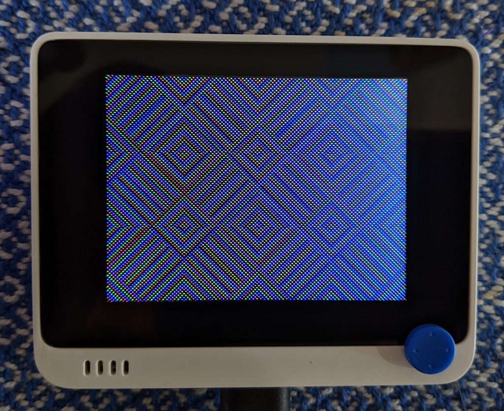
# MicroPython / Seeed Wio Terminal / SAMD51
# Wio-Terminal-Screen.py - output something on the ILI9341 screen
# scruss, 2022-10
# -*- coding: utf-8 -*-


from time import sleep
from ili9341 import Display, color565
from machine import Pin, SPI


def wheel565(pos):
    # Input a value 0 to 255 to get a colour value.
    # The colours are a transition r - g - b - back to r.
    # modified to return RGB565 value for ili9341 - scruss
    (r, g, b) = (0, 0, 0)
    if (pos < 0) or (pos > 255):
        (r, g, b) = (0, 0, 0)
    if pos < 85:
        (r, g, b) = (int(pos * 3), int(255 - (pos * 3)), 0)
    elif pos < 170:
        pos -= 85
        (r, g, b) = (int(255 - pos * 3), 0, int(pos * 3))
    else:
        pos -= 170
        (r, g, b) = (0, int(pos * 3), int(255 - pos * 3))
    return (r & 0xF8) << 8 | (g & 0xFC) << 3 | b >> 3


# screen can be a little slow to turn on, so use built-in
# LED to signal all is well
led = Pin("LED_BLUE", Pin.OUT)

backlight = Pin("LED_LCD", Pin.OUT)  # backlight is not a PWM pin
spi = SPI(
    7, sck=Pin("LCD_SCK"), mosi=Pin("LCD_MOSI"), miso=Pin("LCD_MISO"), baudrate=4000000
)
display = Display(spi, dc=Pin("LCD_D/C"), cs=Pin("LCD_CS"), rst=Pin("LCD_RESET"))
display.display_on()
display.clear()
led.on()  # shotgun debugging, embedded style
backlight.on()

# use default portrait settings: x = 0..239, y = 0..319
dx = 3
dy = 4
x = 3
y = 4
i = 0

try:
    while True:
        # display.draw_pixel(x, y, wheel565(i))
        display.fill_hrect(x, y, 3, 4, wheel565(i))
        i = (i + 1) % 256
        x = x + dx
        y = y + dy
        if x <= 4:
            dx = -dx
        if x >= 234:
            dx = -dx
        if y <= 5:
            dy = -dy
        if y >= 313:
            dy = -dy
except:
    backlight.off()
    led.off()
    display.display_off()
MIDI seems to be absurdly complex. In all the files I looked at, there didn’t seem to be much of a standard in encoding whether the note duration was in the NOTE_ON event or the NOTE_OFF event. Eventually, I managed to fudge a tiny single channel file that had acceptable note durations in the NOTE_OFF events. Here is the file:
# extremely crude MicroPython MIDI demo
# MicroPython / Raspberry Pi Pico - scruss, 2022-08
# see https://github.com/bixb922/umidiparser

import umidiparser
from time import sleep_us
from machine import Pin, PWM

# pin 26 - GP20; just the right distance from GND at pin 23
#  to use one of those PC beepers with the 4-pin headers
pwm = PWM(Pin(20))
led = Pin('LED', Pin.OUT)


def play_tone(freq, usec):
    # play RTTL/midi notes, also flash onboard LED
    # original idea thanks to
    #   https://github.com/dhylands/upy-rtttl
    print('freq = {:6.1f} usec = {:6.1f}'.format(freq, usec))
    if freq > 0:
        pwm.freq(int(freq))       # Set frequency
        pwm.duty_u16(32767)       # 50% duty cycle
    led.on()
    sleep_us(int(0.9 * usec))     # Play for a number of usec
    pwm.duty_u16(0)               # Stop playing for gap between notes
    led.off()
    sleep_us(int(0.1 * usec))     # Pause for a number of usec


# map MIDI notes (0-127) to frequencies. Note 69 is 440 Hz ('A4')
freqs = [440 * 2**((float(x) - 69) / 12) for x in range(128)]

for event in umidiparser.MidiFile("lg2.mid", reuse_event_object=True):
    if event.status == umidiparser.NOTE_OFF and event.channel == 0:
        play_tone(freqs[event.note], event.delta_us)
This isn’t be any means a general MIDI parser, but is rather specialized to play monophonic tunes on channel 0. The result is gloriously awful:
More Micropython programmers — and especially beginners — should know about Awesome MicroPython. It’s a community-curated list of remarkably decent MicroPython libraries, frameworks, software and resources. If you need to interface to a sensor, look there first.
For example, take the INA219 High Side DC Current Sensor. It’s an I²C sensor able to measure up to 26 V, ±3.2 A. It does this by measuring the voltage across a 0.1 ohm precision shunt resistor with its built-in 12-bit ADC. I got a customer return from the store that was cosmetically damaged but still usable, so I thought I’d try it with the simplest module I could find in Awesome MicroPython and see how well it worked.
I guess I needed a test circuit too. Using all of what was immediately handy — a resistor I found on the bench and measured at 150.2 ohm — I came up with this barely useful circuit:
Should indicate a current of 3.3 / (150.2 + 0.1) = 21.96 mA
The INA219 would be happier with a much higher current to measure, but I didn’t have anything handy that could do that.
Looking in Awesome MicroPython’s Current section, I found robert-hh/INA219: INA219 Micropython driver. It doesn’t have much (okay, any) documentation, but it’s a very small module and the code is easy enough to follow. I put the ina219.py module file into the /lib folder of a WeAct Studio RP2040 board, and wrote the following code:
# INA219 demo - uses https://github.com/robert-hh/INA219

from machine import Pin, I2C
import ina219

i = I2C(0, scl=Pin(5), sda=Pin(4))
print("I2C Bus Scan: ", i.scan(), "\n")

sensor = ina219.INA219(i)
sensor.set_calibration_16V_400mA()

# my test circuit is 3V3 supply through 150.2 ohm resistor
r_1 = 150.2
r_s = 0.1  # shunt resistor on INA219 board

# current is returned in milliamps
print("Current       / mA: %8.3f" % (sensor.current))
# shunt_voltage is returned in volts
print("Shunt voltage / mV: %8.3f" % (sensor.shunt_voltage * 1000))
# estimate supply voltage from known resistance * sensed current
print("3V3 (sensed)  / mV: %8.3f" % ((r_1 + r_s) * sensor.current))
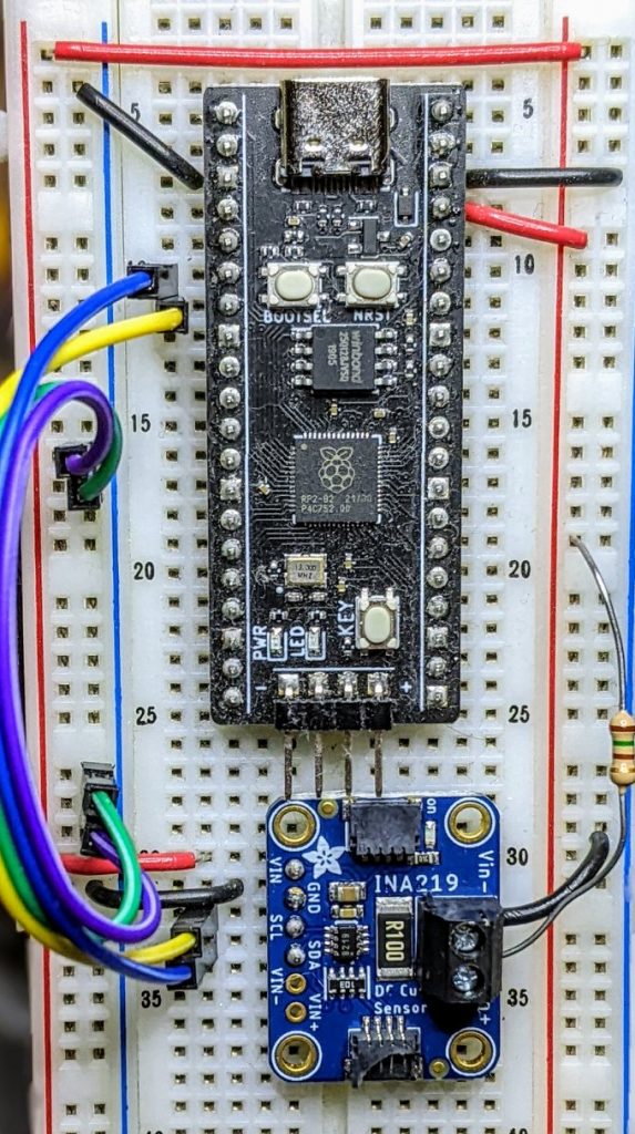
with everything wired up like this (Blue = SDA, Yellow = SCL):
all of the wires
Running it produced this:
I2C Bus Scan:  [64]

Current       / mA:   22.100
Shunt voltage / mV:    2.210
3V3 (sensed)  / mV: 3321.630
So it’s showing just over 22 mA: pretty close to what I calculated!
In early 2013, I must’ve been left unsupervised for too long since I made The Quite Rubbish Clock:
It still isn’t human readable …
Written in (Owen Wilson voice) kind of an obsolete vernacular and running on hardware that’s now best described as “quaint”, it was still absurdly popular at the time. Raspberry Pis were still pretty new, and people were looking for different things to do with them.
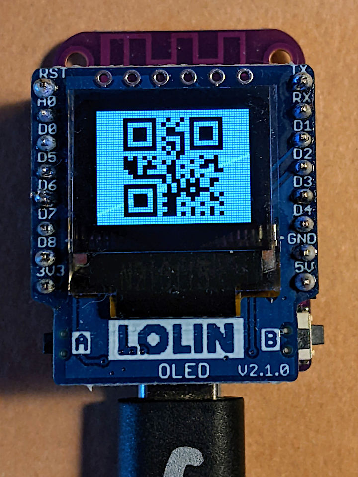
I happened across the JASchilz/uQR: QR Code Generator for MicroPython the other day, and remembered I had some tiny OLED screens that were about the same resolution as the old Nokia I’d used in 2013. I wondered: could I …?
OLED Shield on a LOLIN S2 Mini: very smol indeed
The board is a LOLIN S2 Mini with a OLED 0.66 Inch Shield on top, all running MicroPython. One limitation I found in the MicroPython QR library was that it was very picky about input formats, so it only displays the time as HHMMSS with no separators.
Source, of course:
# -*- coding: utf-8 -*-
# yes, the Quite Rubbish Clock rides again ...
# scruss, 2022-06-30
# MicroPython on Lolin S2 Mini with 64 x 48 OLED display
# uses uQR from https://github.com/JASchilz/uQR
# - which has problems detecting times with colons

from machine import Pin, I2C, RTC
import s2mini  # on Lolin ESP32-S2 Mini
import ssd1306
from uQR import QRCode

WIDTH = 64  # screen size
HEIGHT = 48
SIZE = 8  # text size
r = RTC()

# set up and clear screen
i2c = I2C(0, scl=Pin(s2mini.I2C_SCL), sda=Pin(s2mini.I2C_SDA))
oled = ssd1306.SSD1306_I2C(WIDTH, HEIGHT, i2c)
oled.fill(0)


def snazz():
    marquee = [
        "   **",
        "   **",
        "   **",
        "   **",
        "   **",
        "********",
        " ******",
        "  ****",
        "   **",
        " quite",
        "rubbish",
        " clock",
        "  mk.2",
        "<scruss>",
        " >2022<"
    ]
    for s in marquee:
        oled.scroll(0, -SIZE)  # scroll up one text line
        oled.fill_rect(0, HEIGHT-SIZE, WIDTH,
                       SIZE, 0)  # blank last line
        oled.text("%-8s" % s, 0, HEIGHT-SIZE)  # write text
        oled.show()
        time.sleep(0.25)
    time.sleep(5)
    oled.fill(1)
    oled.show()


snazz()  # tedious crowd-pleasing intro

qr = QRCode()
while True:
    qr.add_data("%02d%02d%02d" % r.datetime()[4:7])
    qr.border = 1  # default border too big to fit small screen
    m = qr.get_matrix()
    oled.fill(1)
    for y in range(len(m)):
        for x in range(len(m[0])):
            # plot a double-sized QR code, centred, inverted
            oled.fill_rect(9 + 2*x, 1 + 2*y, 2, 2, not m[y][x])
    oled.show()
    time.sleep(0.05)
    qr.clear()
If your output is glitchy, you might need to put the following in boot.py:
import machine
machine.freq(240000000)
This increases the ESP32-S2’s frequency from 160 to 240 MHz.
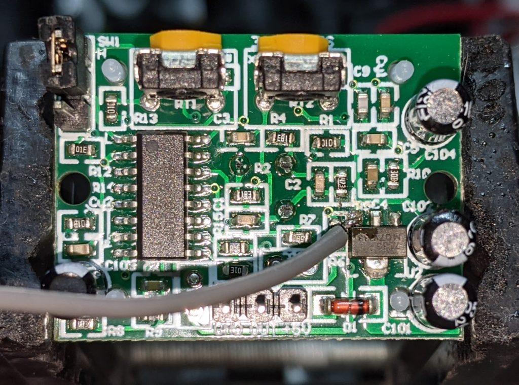
slightly dodgy soldering of a grey jumper wire to the Vout pin of the PIR’s voltage regulator
Consider the Adafruit PIR (motion) sensor (aka PIR Motion Sensor, if you’re in Canada). Simple, reliable device, but only runs from a 5 V supply. Yes, there are smaller PIRs that run off 3.3 V, but if this is what you have, you need to do some soldering. Annoyingly, the sensor on the board is a 3.3 V part, but the carrier was designed in Olden Tymes when King 5 V ruled.
You can try powering it from 3.3 V, but it’ll go all off on its own randomly as its own power supply won’t be supplying enough voltage. There are a couple of sites on how to modify these PIRs that either describe old kit you can’t get any more, or do it completely wrongly. Just one post on the Adafruit support forum gets it right.
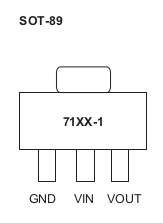
One way of doing this is to provide 3.3 V directly to the output pin of the voltage regulator, and ignore the 5 V power line entirely. The regulator’s a SOT89-3 part that looks a bit like this:
wee leggy thing
In the photo above, it’s flipped over. Whichever way it’s oriented, we want to put power directly into the Vout pin. There may be easier points to solder this to than a tiny surface mount pin (almost definitely one of the capacitors) but this has held for me.
How to use it in MicroPython? Like the TTP223 capacitive touch sensors I looked at before, a PIR gives a simple off/on output, so you can use something like this:
from machine import Pin
from time import sleep_ms

pir = Pin(21, Pin.IN)

while True:
    print("[", pir.value(), "]")
    sleep_ms(1000)
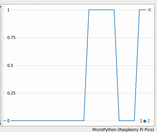
value() will return 1 if there’s movement, 0 if not. There are trigger time and sensitivity potentiometers to fiddle with on the board if you need to tweak the output.
Thonny plotter output showing a couple of movement detections. High output (on my device) stays up for about 4 seconds, so you can be pretty leisurely about polling PIRs
Just remember: don’t connect the 5 V power line if you make this mod. I’m not responsible for any smoke emitted if you do — but I can always sell you a replacement …
This is almost too trivial to write up, as the TTP223 does exactly what you’d expect it to do with no other components.
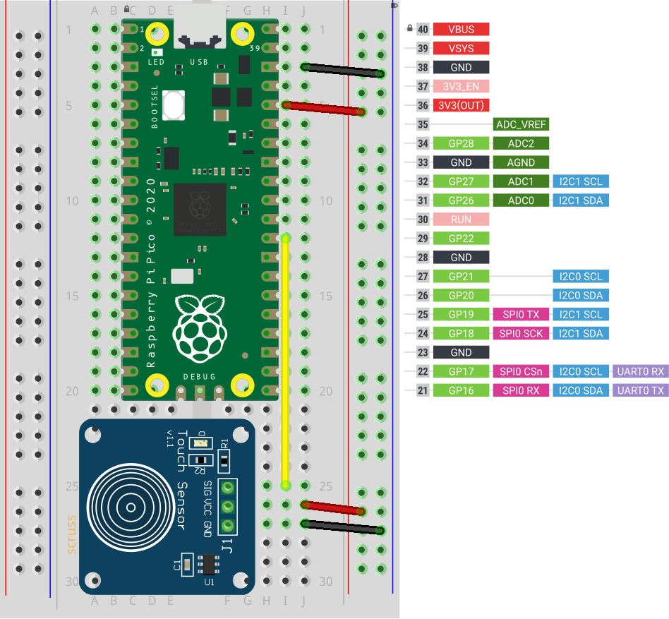
TTP223 sensor board connected to GP22 / physical pin 29
Breakout boards for the TTP223 capacitive touch sensor come in a whole variety of sizes. The ones I got from Simcoe DIY are much smaller, have a different connection order, and don’t have an indicator LED. What they all give you, though, is a single touch/proximity switch for about $1.50
Trivial code to light the Raspberry Pi Pico’s LED when a touch event is detected looks like this:
import machine
touch = machine.Pin(22, machine.Pin.IN)
led = machine.Pin(25, machine.Pin.OUT)

while True:
    led.value(touch.value())
For the default configuration, the sensor’s output goes high while a touch is detected, then goes low. This might not be the ideal configuration for you, so these sensor boards have a couple of solder links you can modify:
Active Low — sometimes you want a switch to indicate a touch with a low / 0 V signal. On the boards I have, the A link controls that: put a blob of solder across it to reverse the switch’s sense.
Toggle — if you want the output to stay latched at one level until you touch it again, a blob of solder across the T link will do that. Unlike a mechanical switch, this won’t stay latched after a power cycle, though.
And that’s all it does. Sometimes it’s nice to have a sensor that does exactly one thing perfectly well.
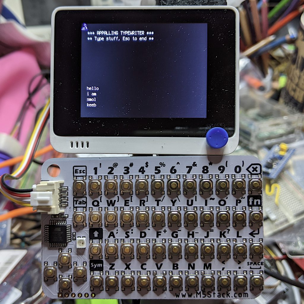
it really is the size of a credit card (running with a SeeedStudio Wio Terminal)
I got one of these CardKB Mini Keyboards to see if I could use it for small interactives with MicroPython devices. It’s very small, and objectively not great as a mass data entry tool. “Better than a Pocket C.H.I.P. keyboard” is how I’d describe the feel. It’s also pretty reliable.
It’s got an I²C Grove connector, and its brains are an ATMega chip just like an Arduino. It’s strictly an ASCII keyboard: that is, it sends the 8-bit ASCII code of the key combination you pressed. It doesn’t send scan codes like a PC keyboard. The driver source is in the CardKB m5-docs, so if you really felt ambitious you could write a scan code-like firmware for yourself.
The device appears at I²C peripheral address 95, and returns a single byte when polled. That byte’s either 0 if no key was pressed, or the character code of what was pressed. The Esc key returns chr(27), and Enter returns CR. If you poll the keyboard too fast it seems to lose the plot a little, so a tiny delay seems to help
Here’s a small demo for MicroPython that acts as the world’s worst typewriter:
# M5Stack CardKB tiny keyboard - scruss, 2021-06
# MicroPython - Raspberry Pi Pico

from machine import Pin, I2C
from time import sleep_ms

i2c = I2C(1, scl=Pin(7), sda=Pin(6))
cardkb = i2c.scan()[0]  # should return 95
if cardkb != 95:
    print("!!! Check I2C config: " + str(i2c))
    print("!!! CardKB not found. I2C device", cardkb,
          "found instead.")
    exit(1)

ESC = chr(27)
NUL = '\x00'
CR = "\r"
LF = "\n"
c = ''

print("*** APPALLING TYPEWRITER ***")
print("** Type stuff, Esc to end **")

while (c != ESC):
    # returns NUL char if no character read
    c = i2c.readfrom(cardkb, 1).decode()
    if c == CR:
        # convert CR return key to LF
        c = LF
    if c != NUL or c != ESC:
        print(c, end='')
    sleep_ms(5)
And here’s the CircuitPython version. It has annoying tiny differences. It won’t let me use the I²C Grove connector on the Wio Terminal for some reason, but it does work much the same:
# M5Stack CardKB tiny keyboard - scruss, 2021-06
# CircuitPython - SeeedStudio Wio Terminal
# NB: can't use Grove connector under CPY because CPY

import time
import board
import busio

i2c = busio.I2C(board.SCL, board.SDA)

while not i2c.try_lock():
    pass

cardkb = i2c.scan()[0]  # should return 95
if cardkb != 95:
    print("!!! Check I2C config: " + str(i2c))
    print("!!! CardKB not found. I2C device", cardkb,
          "found instead.")
    exit(1)

ESC = chr(27)
NUL = '\x00'
CR = "\r"
LF = "\n"
c = ''
b = bytearray(1)

# can't really clear screen, so this will do
for i in range(12):
    print()
print("*** APPALLING TYPEWRITER ***")
print("** Type stuff, Esc to end **")
for i in range(8):
    print()

while (c != ESC):
    # returns NUL char if no character read
    i2c.readfrom_into(cardkb, b)
    c = b.decode()
    if c == CR:
        # convert CR return key to LF
        c = LF
    if c != NUL or c != ESC:
        print(c, end='')
    time.sleep(0.005)

# be nice, clean up
i2c.unlock()
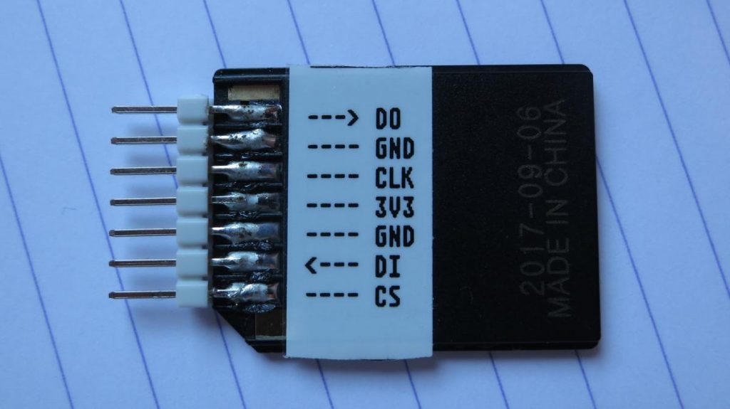
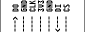
micro-SD adapter + pins + solder = working SD interface
It’s only a serial SPI interface, but you can’t beat the price. It should only be used with 3.3 V micro-controllers like the Raspberry Pi Pico, since micro-SD cards don’t like 5 V directly atall.
You might want to pre-tin the pins and apply some extra flux on both surfaces, because these pads are thin and you don’t want to melt them. I used my standard SnAgCu lead-free solder without trouble, though.
got a label maker? This label’s the same length as an SD card is wide, as shown above. Made entirely with netpbm
You only need to use one of the Ground connections for the card to work.
I built a DS0150 — successfully, on my second try — and wanted to measure something. My demo MicroPython program from MicroPython on the terrible old ESP8266-12 Development Board has been running since May 2020, and the RGB LED’s red channel is conveniently broken out to a header. Since the DSO150 has precisely one channel, it let me see the how the PWM duty cycle affects the voltage (and brightness) of the LED.
I can’t think of oscilloscopes without being reminded of a scene from one of my favourite sci-fi books, The Reproductive System by John Sladek. Cal, the hapless new hire in the Wompler toy factory-turned-military research lab, is showing the boss some equipment while making up more and more extravagant names for them for the clueless owner:
At each exhibit, Grandison [Wompler] would pause while Cal named the piece of equipment. Then he would repeat the name softly, with a kind of wonder, nod sagely, and move on. Cal was strongly reminded of the way some people look at modern art exhibitions, where the labels become more important to them than the objects. He found himself making up elaborate names. “And this, you’ll note, is the Mondriaan Modular Mnemonicon.†“—onicon, yes.†“And the Empyrean diffractosphere.†“—sphere. Mn. I see.†Nothing surprised Grandison, for he was looking at nothing. Cal became wilder. Pointing to Hita’s desk, he said, “The chiarascuro thermocouple.†“Couple? Looks like only one, to me. Interesting, though.†A briar pipe became a “zygotic pipette,†the glass ashtray a “Piltdown retort,†and the lamp a “phase-conditioned Aeolian.†Paperclips became “nuances.†“Nuances, I see. Very fine. What’s that thing, now?†He pointed to an oscilloscope. Cal took a deep breath. “Its full name,†he said, “is the Praetorian eschatalogical morphomorphic tangram, Endymion-type, but we usually just call it a ramification.†The old man fixed him with a stern black eye. “Are you trying to be funny or something? I mean, I may not be a smart-aleck scientist, but I sure as hell know a television when I see one.†Cal assured him it was not a television, and proved it by switching it on. “See,†he said, pointing to a pattern of square waves, “there are the little anapests.â€
— The Reproductive system, by John Sladek (text copypasta from Grey Goo in the 1960s)
So we were displaying roughly 500 anapests/s there. Not bad, not bad at all …
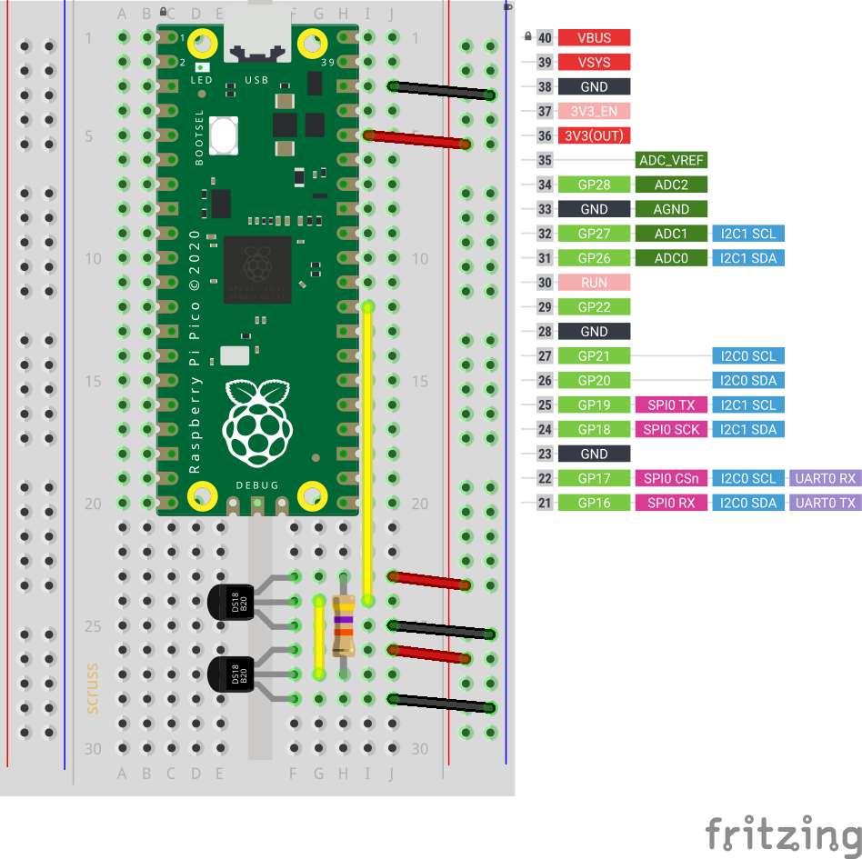
Updated: Thanks to Ben, who noticed the Fritzing diagrams had the sensors the wrong way round. Fixed now…
Hidden away in the Pico MicroPython guide is a hint that there may be more modules installed in the system than they let on. In the section about picotool, the guide has a seemingly innocuous couple of lines:
The third and fourth ‘frozen modules’ are a giveaway: it shows that support for the popular Dallas/Maxim DS18x20 1-Wire temperature sensors is built in. Nowhere else in the guide are they mentioned. I guess someone needs to write them up.
DS18x20 digital temperature sensors – usually sold as DS18B20 by Maxim and the many clone/knock-off suppliers – are handy. They can report temperatures from -55 to 125 °C, although not every sensor will withstand that range. They come in a variety of packages, including immersible sealed units. They give a reliable result, free from ADC noise. They’re fairly cheap, the wiring’s absurdly simple, and you can chain long strings of them together from the same input pin and they’ll all work. What they aren’t, though, is fast: 1-Wire is a slow serial protocol that takes a while to query all of its attached devices and ferry the results back to the controller. But when we’re talking about environmental temperature, querying more often than a few times a minute is unnecessary.
So this is the most complex way you can wire up a DS18x20 sensor:
Raspberry Pi Pico connected to a single DS18x20 sensor
and this is how it’s wired:
   DS18X20    Pico
   =========  =========
   VDD      ? 3V3
              /
     --47 k?--
    /
   DQ       ? GP22
   GND      ? GND

 (47 k? resistor between DQ and 3V3 as pull-up)
Adding another sensor is no more complicated: connect it exactly as the first, chaining the sensors together –
Two DS18x20 sensors, though quite why you’d want two temperature sensors less than 8 mm apart, I’ll never know. Imagine one is a fancy immersible one on a long cable
The code is not complex, either:
# Raspberry Pi Pico - MicroPython DS18X20 Sensor demo
# scruss - 2021-02
# -*- coding: utf-8 -*-

from machine import Pin
from onewire import OneWire
from ds18x20 import DS18X20
from time import sleep_ms
from ubinascii import hexlify    # for sensor ID nice display

ds = DS18X20(OneWire(Pin(22)))
sensors = ds.scan()

while True:
    ds.convert_temp()
    sleep_ms(750)     # mandatory pause to collect results
    for s in sensors:
        print(hexlify(s).decode(), ":", "%6.1f" % (ds.read_temp(s)))
        print()
    sleep_ms(2000)
This generic code will read any number of attached sensors and return their readings along with the sensor ID. The sensor ID is a big ugly hex string (the one I’m using right now has an ID of 284c907997070344, but its friends call it ThreeFourFour) that’s unique across all of the sensors that are out there.
If you’re reading a single sensor, the code can be much simpler:
# Raspberry Pi Pico - MicroPython 1x DS18X20 Sensor demo
# scruss - 2021-02
# -*- coding: utf-8 -*-

from machine import Pin
from onewire import OneWire
from ds18x20 import DS18X20
from time import sleep_ms

ds = DS18X20(OneWire(Pin(22)))
sensor_id = ds.scan()[0]  # the one and only sensor

while True:
    ds.convert_temp()
    sleep_ms(750)         # wait for results
    print(ds.read_temp(sensor_id), " °C")
    sleep_ms(2000)
The important bits of the program:
Tell your Pico you have a DS18x20 on pin GP22: ds = DS18X20(OneWire(Pin(22)))
Get the first (and only) sensor ID: sensor_id = ds.scan()[0]
Every time you need a reading:
Request a temperature reading: ds.convert_temp()
Wait for results to come back: sleep_ms(750)
Get the reading back as a floating-point value in °C: ds.read_temp(sensor_id)
That’s it. No faffing about with analogue conversion factors and mystery multipliers. No “will it feel like returning a result this time?” like the DHT sensors. While the 1-Wire protocol is immensely complicated (Trevor Woerner has a really clear summary: Device Enumeration on a 1-Wire Bus) it’s not something you need to understand to make them work.
Rather than use the Adafruit trade name, these are more properly called WS2812 LEDs. Each one contains a tiny microcontroller and it only takes three connections to drive a long chain of addressable colour LEDs. The downside is that the protocol to drive these is a bit of a bear, and really needs an accurate, fast clock signal to be reliable.
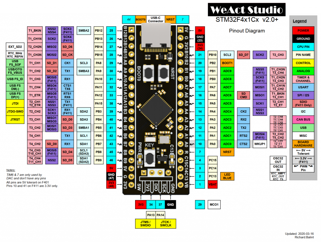
The STM32F411 chip does have just such a clock, and the generic micropython-ws2812 library slightly misuses the SPI bus to handle the signalling. The wiring’s simple:
F411 GND to WS2812 GND;
F411 3V3 to WS2812 5V;
F411 PA7 (SPI1_MOSI) PB15 (SPI2_MOSI) to WS2812 DIn
Next, copy ws2812.py into the WeAct F411’s flash. Now create a script to drive the LEDs. Here’s one to drive 8 LEDs, modified from the library’s advanced example:
# -*- coding: utf-8 -*-

import time
import math

from ws2812 import WS2812

ring = WS2812(spi_bus=2, led_count=8, intensity=0.1)

def data_generator(led_count):
    data = [(0, 0, 0) for i in range(led_count)]
    step = 0
    while True:
        red = int((1 + math.sin(step * 0.1324)) * 127)
        green = int((1 + math.sin(step * 0.1654)) * 127)
        blue = int((1 + math.sin(step * 0.1)) * 127)
        data[step % led_count] = (red, green, blue)
        yield data
        step += 1

for data in data_generator(ring.led_count):
    ring.show(data)
    time.sleep_ms(100)
Previously I said you’d see your WS2812s flicker and shimmer from the SPI bus noise. I thought it was cool, but I suspect it was also why the external flash on my F411 board just died. By pumping data into PA7, I was also hammering the flash chip’s DI line …
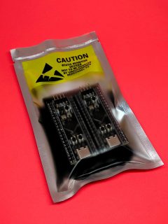
Volker Forster at Universal Solder was kind enough to send me a couple of these boards for free when I asked about availability. By way of thanks, I’m writing this article about what’s neat about these micro-controller boards.
always neat packaging from Universal Solder
Can I just say how nicely packaged Universal Solder’s own or customized products are? They want it to get to you, and they want it to work.
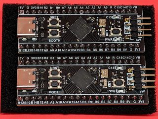
I’d previously played around with Blue Pill and Black Pill boards with limited success. Yes, they’re cheap and powerful, but getting the toolchain to work reliably was so much work. So when I read about the WeAct STM32F411CEU6 board on the MicroPython forum, I knew they’d be a much better bet.
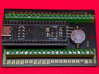
Canaduino Black Pill Carrier Board with STM32F411 (and battery) installed
Let’s start with the STM32 Screw Terminal Adapter:
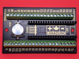
Canaduino Black Pill Carrier Board (front)
It’s a neat, solid board built on a black 1.6 mm thick PCB. Apart from the obvious screw terminals — essential for long-term industrial installations — it adds three handy features:
a real-time clock battery. If you’re using a micro-controller for data logging, an RTC battery helps you keep timestamps accurate even if the device loses power.
mounting holes! This may seem a small thing, but if you can mount your micro-controller solidly, your project will look much more professional and last longer too.
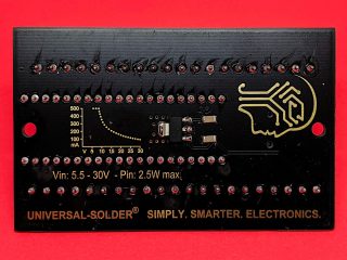
A 6–30 V DC regulator. Connect this voltage between Vin and GND and the regulator will keep the board happy. From the helpful graph on the back of the board, it doesn’t look as if things start getting efficient until around 12 V, but it’s really nice to have a choice.
Canaduino Black Pill Carrier Board (back)
I made a little slip-case for this board so it wouldn’t short out on the workbench. The project is here: Canaduino STM32 Screw Terminal board tray and you can download a snapshot here:
Gone are the lumpy pin headers of the earlier Blue and Black Pill boards, replaced by tactile switches. The iffy micro USB connectors are replaced by much more solid USB C connectors. According to STM32-base, the STM32F411 has:
100 MHz ARM Cortex-M4 core. This brings fast (single-precision) floating point so you don’t have to fret over integer maths
512 K Flash, 128 K RAM. MicroPython runs in this, but more flash is always helpful
Lots of digital and analogue I/O, including a 12-bit ADC
A user LED and user input switch.
About the only advanced features it’s missing are a true RNG, a DAC for analogue outputs, and WiFi. But on top of all this, Volker added:
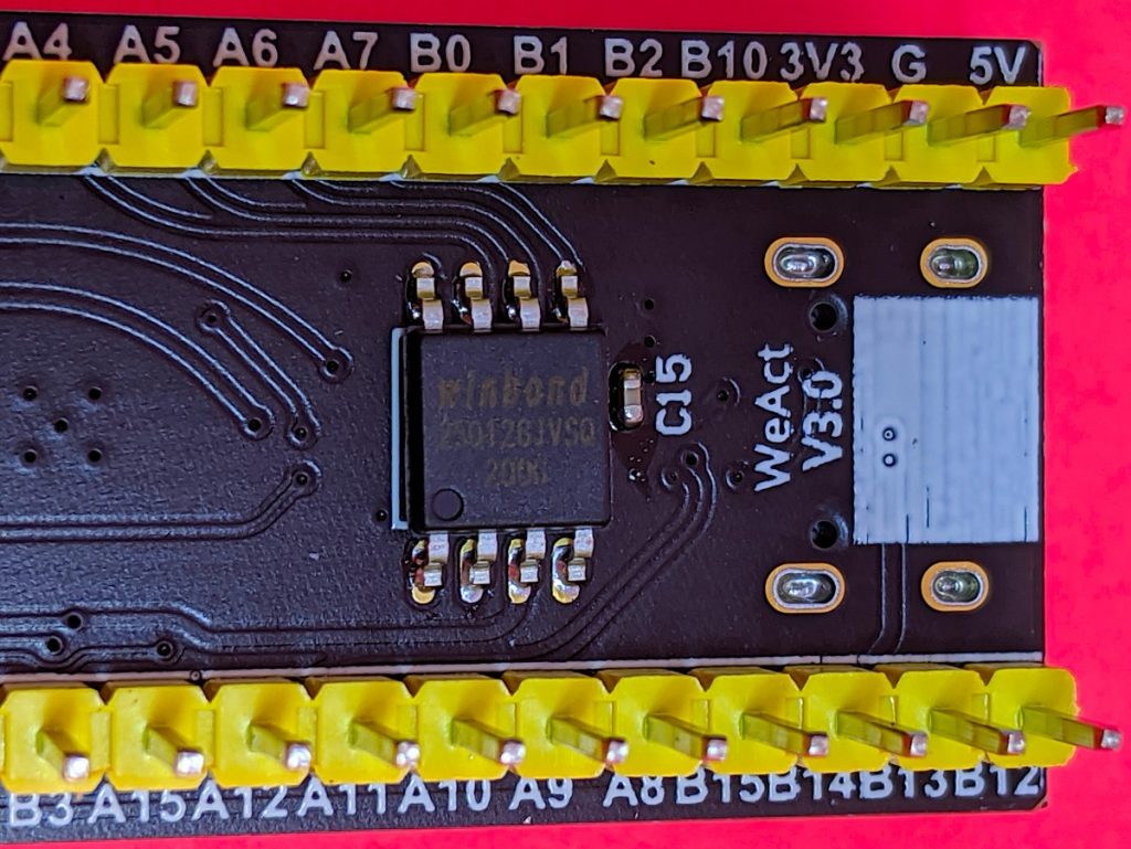
the all-important 128 Mbit flash chip (and capacitor) fitted by Universal Solder
128 Mbit of Flash! This gives the board roughly 16 MB of storage that, when used with MicroPython, appears as a small USB drive for your programs and data. I found I was able to read the ADC more than 22,000 times/second under MicroPython, so who needs slow-to-deploy compiled code?
I had to run make a couple of times before it would build, but it built and installed quickly. This board doesn’t take UF2 image files that other boards use, so the installation is a little more complicated than other. But it works!
Once flashed, you should have a USB device with two important MicroPython files on it: boot.py and main.py. boot.py is best left alone, but main.py can be used for your program. I’m going into more details in a later article, but how about replacing the main.py program with the fanciest version if Blink you ever saw:
# main.py -- fancy Blink (scruss, 2020-05)

from pyb import LED
from machine import Timer
tim = Timer(-1)
tim.init(period=1000, mode=Timer.PERIODIC,
         callback=lambda t: LED(1).toggle())
None of that blocking delay() nonsense: we’re using a periodic timer to toggle the user LED every second!
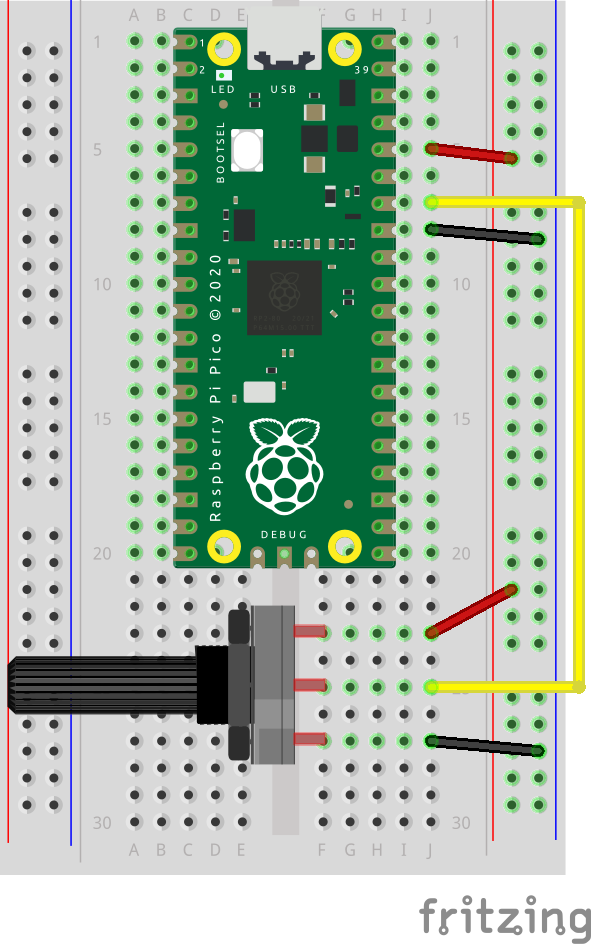
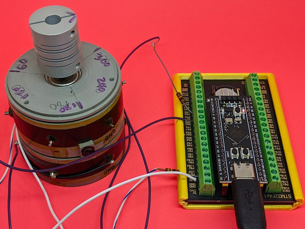
debugging the mystery huge potentiometer using two ADC channels
I’m really impressed with the Universal Solder-modified board as an experimentation/discovery platform. MicroPython makes development and testing really quick and easy.
[and about the mystery huge potentiometer: it’s a Computer Instruments Corporation Model 206-IG multi-turn, multi-track potentiometer I picked up from the free table at a nerd event. I think it’s a 1950s (so Servo-control/Cybernetics age) analogue equivalent of a shaft encoder, looking at the patent. Best I can tell is that each pot (there are two, stacked, with precision bearings) appears to have two 120° 10k ohm sweep tracks offset 90° to one another. The four wipers are labelled -COS, -SIN, +COS and +SIN. If anyone knows more about the thing, let me know!]
Hey! This doesn’t work any more, as CircuitPython changed and I haven’t found a way to update it with the new interpreter.
Since there are seven touch pads on a Circuit Playground Express, that’s enough for traditional 3-chord (â… , â…£, â…¤) songs in the keys of C, D and G. That leaves one pad extra for a â…¥min chord for so you can play Neutral Milk Hotel songs in G, of course.
The code is really simple: poll the seven touch pads on the CPX, and if one of them is touched, play a sample and pause for a short time:
# Circuit Playground Express Chord Guitar
# scruss - 2017-12

# these libraries should be installed by default in CircuitPython
import touchio
import board
import time
import neopixel
import digitalio
import audioio

# touch pins, anticlockwise from battery connector
touch_pins= [
    touchio.TouchIn(board.A1),
    touchio.TouchIn(board.A2),
    touchio.TouchIn(board.A3),
    touchio.TouchIn(board.A4),
    touchio.TouchIn(board.A5),
    touchio.TouchIn(board.A6),
    touchio.TouchIn(board.A7)
]

# 16 kHz 16-bit mono audio files, in same order as pins
chord_files = [
    "chord-C.wav",
    "chord-D.wav",
    "chord-E.wav",
    "chord-Em.wav",
    "chord-F.wav",
    "chord-G.wav",
    "chord-A.wav"
]

# nearest pixels to touch pads
chord_pixels = [ 6, 8, 9, 0, 1, 3, 4 ]

# set up neopixel access
pixels = neopixel.NeoPixel(board.NEOPIXEL, 10, brightness=.2)
pixels.fill((0, 0, 0))
pixels.show()

# set up speaker output
speaker_enable = digitalio.DigitalInOut(board.SPEAKER_ENABLE)
speaker_enable.switch_to_output(value=True)

# poll touch pins
while True:
    for i in range(len(touch_pins)):
        # if a pin is touched
        if touch_pins[i].value:
            # set nearest pixel
            pixels[chord_pixels[i]] = (0, 0x10, 0)
            pixels.show()
            # open and play corresponding file
            f=open(chord_files[i], "rb")
            a = audioio.AudioOut(board.A0, f)
            a.play()
            # blank nearest pixel
            pixels[chord_pixels[i]] = (0, 0, 0)
            pixels.show()
            # short delay to let chord sound
            # might want to try this a little shorter for faster play
            time.sleep(0.2)
This is roughly how I synthesized the samples, but I made them quieter (the MEMS speaker on the CPX went all buzzy at full volume, and not in a good way) and added a bit of reverb. Here’s the sox command from the modified script:
Really, you do want to take a look at shortening the delay between the samples: you want it long enough for all of the notes of the chord to sound, but short enough that you can play faster songs. I came up with something that worked for me, kinda, and quickly; it’s worth fixing if you have the time.
I’m not proud of this, but I made it so you won’t have to:
Craig at Elmwood Electronics very kindly gave me an ADABOX 006. It’s based around Adafruit’s Circuit Playground Express which just happens to feature a small built-in speaker, IR remote control and the ability to play back audio samples. You see where this is going, don’t you?