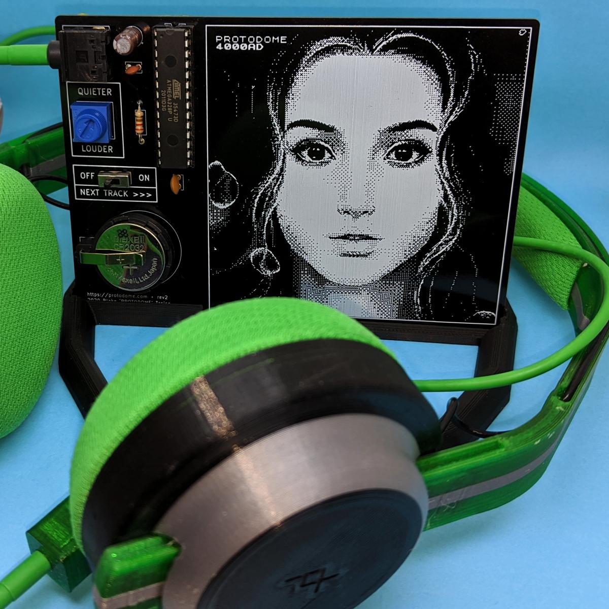
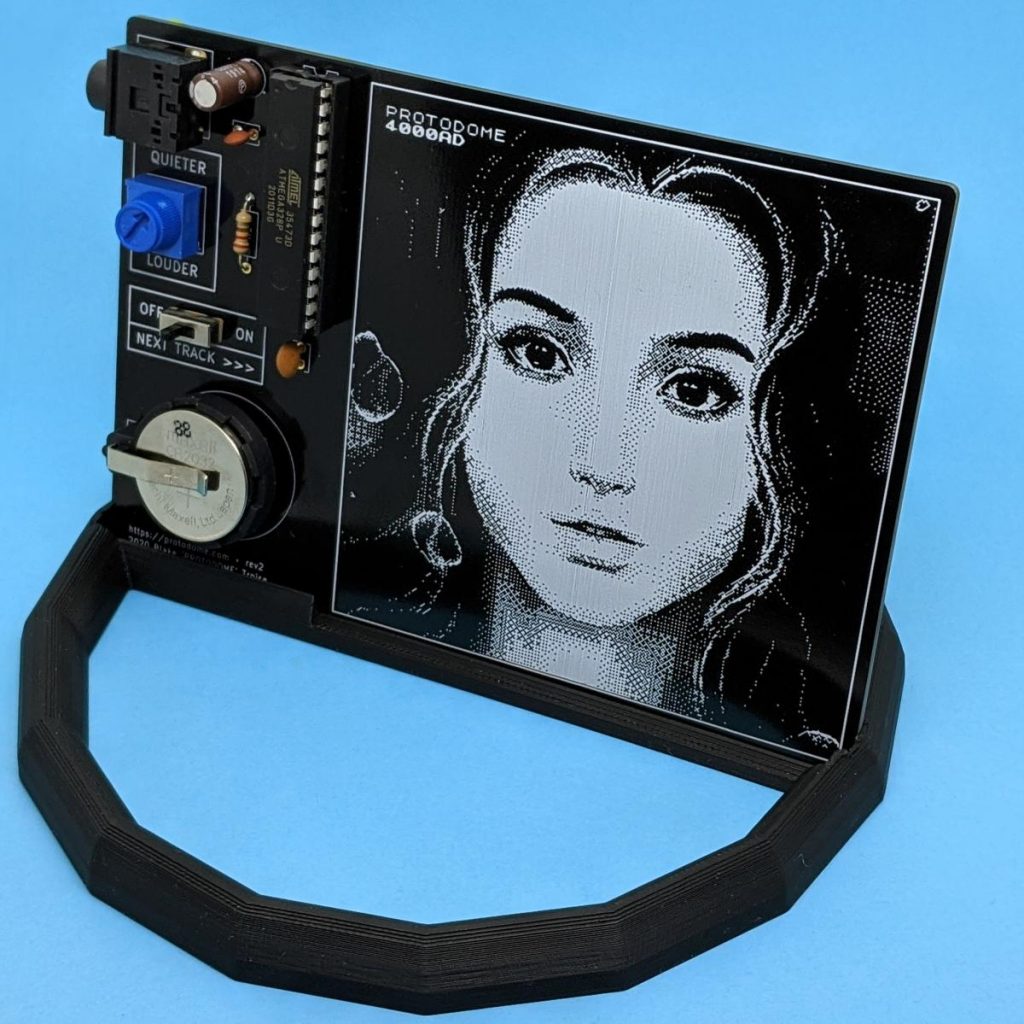
4000AD album PCB in stand, with Print+ 3D printed headphones in foreground
4000AD album PCB in stand, with Print+ 3D printed headphones in foreground
So Dr. Blake “PROTODOME†Troise (previously) made a chiptune album that’s entirely synthesized by an Atmel/Microchip ATmega328P microcontroller in realtime. And every chip needs a PCB, right? So Blake released the album as a physical device you can solder up for yourself.
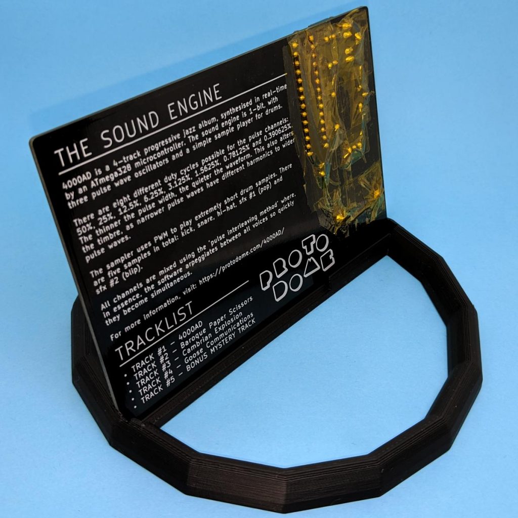
Of course, having the PCB lying flat doesn’t allow you to see Marianne Thompson’s great pixel cover art, or read the liner notes on the back — and risks having the circuit short out on random tinny things on your desk. (Maybe that’s just my desk, though.)
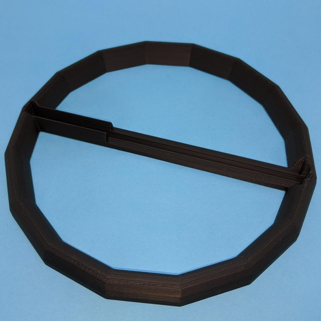
This stand allows you to display the board at a convenient 75° angle, but also allows the PCB to be flipped forward so you can read the liner notes comfortably. Yeah, I may have been a crate-digger at one time.
Six whole tunes ready to play on this tiny chiptune player; a couple are included at the end of this article!
I love the ingenuity that goes into making very tiny projects do very big things. I also love chiptunes. So when I read the metafilter post about PROTODOME’s compositions for the ATtiny85, I was very much there for it.
The circuit to play this is no more than a $2 microcontroller, a lithium coin cell and a speaker or piezo buzzer. The microcontroller has 8 KB of program space and 512 bytes of RAM. The output is a single pin, but with very clever pulse width modulation tricks, sounds like three channels plus percussion.
I remembered I had bought a tube of ATtiny microcontrollers a while back. I knew I had a coin cell and tiny speaker. “I can do this!â€, I thought.
So what follows is tutorial on compiling embedded code for an ATtiny85 microcontroller on Linux. There are larger tutorials out there, there are better tutorials: but there are also many out-of-date and misleading tutorials. This isn’t a general ATtiny development tutorial, but one specialized on getting PROTODOME’s tunes playing on your microcontroller.
Hardware
The very minimum you will need to play the music is:
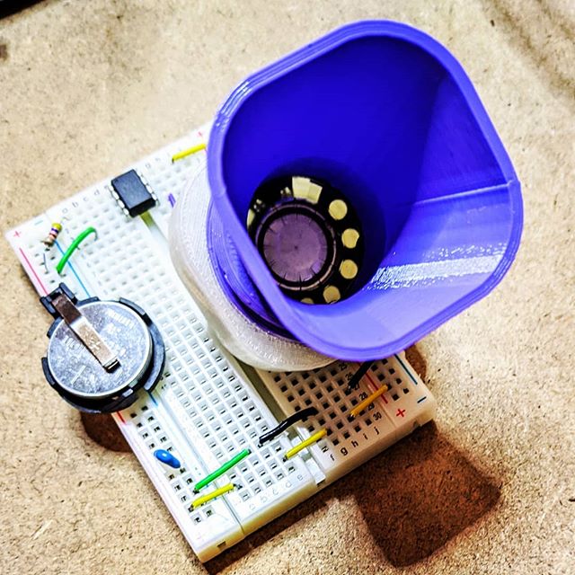
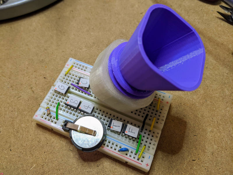
a tiny speaker or piezo buzzer. Either will do, and will be pretty quiet — you’re not getting room-filling fidelity out of this project. The part is Elmwood Electronics small (14mm diameter) piezo element, SparkFun Thin Speaker – 0.5W, Adafruit Mini Metal Speaker w/ Wires. I used a 28 mm headphone driver I got surplus years ago. The snazzy speaker horn in the picture above is designed to fit this and not much else, alas.
a battery and battery holder. Pretty much anything from 3–5 V will do. I used a CR2032 coin cell in a simple holder to feed 3.2 V to the circuit: Elmwood Electronics CR2032, SparkFun Coin Cell Battery Holder – 20mm (PTH). Note you’ll need a battery and something to connect it to the breadboard.
a 10 nF ceramic capacitor, while optional, likely makes the power into the µc a tiny bit smoother
jumper wires to connect everything up.
But that’s not all: you’ll need much more kit to program these tiny chips:
a computer running Linux. Yes, you can do this under Windows and Mac OS, but I don’t know how and there are search engines that care about that more than I do. I tested all of this on a Raspberry Pi 4. Tablets and phones are out, sorry
There are two separate toolchains involved — one to build the mmml-compiler to convert PROTODOME’s compositions to µc embedded C code, and another to compile that to ATtiny85 instructions. We can install it all in one go:
git clone https://github.com/protodomemusic/mmml.git
cd mmml/mmml-compiler
gcc -o mmml-compiler mmml-compiler.c
You can then run the compiler on each of the songs; the album title track, for example:
cd ../demo-songs/4000ad/
../../mmml-compiler/mmml-compiler 4000ad.mmml
âš ï¸ If you get [ERROR 14] Too few channels stated! instead of Successfully compiled! it seems that the compiler isn’t too happy running on some 64-bit systems. I did all my compilation on a Raspberry Pi 4 running Raspbian and all was well. If you can’t get them to compile, I’ve pre-compiled them for you and they’re at the end of this article.
You should now have a musicdata.h file that contains all the tune data. Copy it to the same folder as the mmml-player C code:
cp musicdata.h ../../mmml-player/
cd ../../mmml-player/
That folder now contains the player and one tune data file. Now you need to compile it into AVR instruction to write to your chip:
The end result of what that just did is create a single small file mmml.hex containing the ATtiny85 program instructions for the 8+ minute track 4000AD. If you’re compiling for a different µc, you’ll need a different avr-gcc line:
-mmcu=attiny85 will need to be changed for your µc. avr-gcc –target-help lists the supported targets in the ‘Known MCU names’ section way up at the top of its too-copious output. If you’re using the ATmega32P chip made popular by Arduinos, that option should be -mmcu=atmega328p
-DF_CPU=8000000 tells the compiler that the CPU frequency should be 8 MHz. The AVR µcs can run at a huge range of speeds, but PROTODOME’s music is timed to work at 8 MHz only.
→→→ aside
If you find yourself compiling a few simple AVR projects but want to stop short of a fine-but-overly-complex Makefile project for AVR development, this script to create a hex file from a single embedded C source file might be useful:
In addition to creating a hex file, it also runs the avr-size tool to show you much memory your program uses. The 4000AD tune uses 98% of the ATtiny85’s 8192 byte program space — not quite enough to include that 14 minute extra bass solo, sorry …
â†â†â† end aside
Flashing the chip
So now we do some wiring. If you’re using a dedicated programmer, use jumpers to connect its ICSP port to the ATtiny 85 like this:
                        ________
                       |o   A   |
               Reset  -+ 1  T  8+-  VCC
                       |    t   |
                      -+ 2  i  7+-  SCK
                       |    n   |
                      -+ 3  y  6+-  MISO
                       |    8   |
               GND    -+ 4  5  5+-  MOSI
                       |________|


                 MISO    o1 2o   VCC
                 SCK     o3 4o   MOSI
                 Reset   o5 6o   GND

                          ICSP
                        Connector
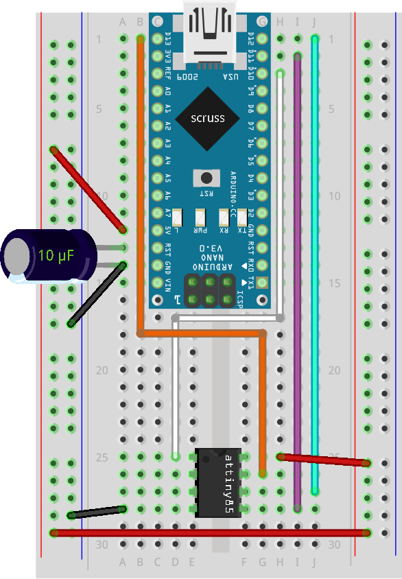
Wire VCC to VCC, MISO to MISO, MOSI to MOSI, SCK to SCK, Reset to Reset and GND to GND. If you’re using an Arduino, you want to do this:
This is ‘OLD_STYLE_WIRING’ for using ArduinoISP, apparently. But it works!
The wiring for that is:
Arduino D10 → ATtiny Pin 1 (Reset)
Arduino GND → ATtiny Pin 4 (GND)
Arduino D11 → ATtiny Pin 5 (MOSI)
Arduino D12 → ATtiny Pin 6 (MISO)
Arduino D13 → ATtiny Pin 7 (SCK)
Arduino 5V → ATtiny Pin 8 (VCC)
You’ll also need to put a 1-10 µF electrolytic capacitor between the Arduino’s Reset and GND pins, but only after you’ve programmed it with the ArduinoISP sketch.
You’re almost there!
Setting up the programmer: USBtinyISP
If you haven’t used one with your computer before, you need to do a little bit of prep so your computer recognizes it. These are modified from a gist:
do sudo vi /etc/udev/rules.d/41-usbtiny.rules
add the line SUBSYSTEM=="usb", ATTR{idVendor}=="1781", ATTR{idProduct}=="0c9f", GROUP="plugdev", MODE="0666"
save and exit
do sudo udevadm control --reload then sudo udevadm trigger
Your system should automatically recognize the device and give you permission to use it without sudo privileges.
Setting up the programmer: ArduinoISP
Load the ArduinoISP sketch (it’s in File → Examples)
Add (or find and uncomment) the line #define USE_OLD_STYLE_WIRING
Upload the code to your Arduino
Connect the 1-10 µF electrolytic capacitor between the Arduino’s Reset and GND pins
To program the mmml.hex you created earlier, you’ll need one of these avrdude commands:
-c usbtiny or -c arduino: programmer type. In addition, the arduino programmer takes additional parameters -P /dev/ttyUSB0 -b 19200 which specify the port (usually /dev/ttyUSB0 or /dev/ttyACM0) and the baud rate (always 19200, unless you changed it in the source of ArduinoISP)
-p attiny85: the chip type, as used in the avr-gcc compiler call way up the top
-U lfuse:w:0xe2:m -U hfuse:w:0xdf:m -U efuse:w:0xff:m: fuses are AVR’s confusing name for configuration bits. You might just have to take my word that this sets an ATtiny85 to use the internal 8 MHz oscillator (as opposed to an external crystal) we told the compiler to use further back. A guide to fuse settings is available at the Engbedded AVR Fuse Calculator
-U flash:w:mmml.hex:i: the hex file we prepared, mmml.hex.
If everything went right with your flashing process, you should see lots of “avrdude: verifying … done. Thank youâ€. If you don’t, likely you missed a connection somewhere.
♫ Playing the tunes! ♫
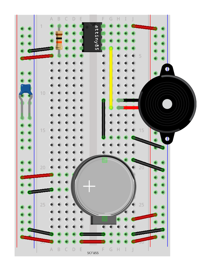
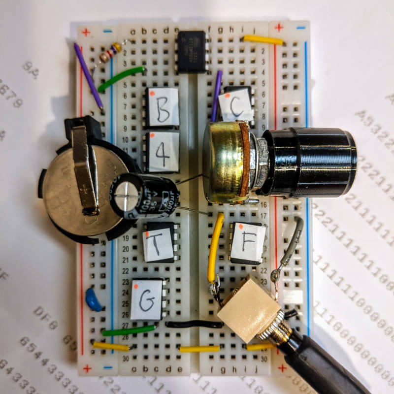
This circuit’s a lot simpler than it looks!
I already described all of the bits in the bill of materials in the Hardware section. If you want it in ASCII art, here’s all there is to it:
If you weren’t able to compile the tunes, I’ve included (with Blake’s permission) source for any AVR µc plus hex files for ATtiny85s here: protodome-mmml-examples.zip
Last but not least, there are a couple of tracks included in the source that aren’t on the 4000AD album. Blake gave me permission to include them here, too:
Fly Me to the Moon by Bart Howard, arranged for ATtiny85 microcontroller by PROTODOME, 2020. Download: fly_me_to_the_moon.mp3Till There was You by Meredith Willson (from the musical ‘The Music Man’), arranged for ATtiny85 microcontroller by PROTODOME, 2020. Download: till_there_was_you.mp3
These weren’t recorded from a tiny speaker (that went badly), but directly to a Marantz solid state recorder. The rig’s the same as the playback one, with the speaker replaced by a potentiometer (for level control), a 100 µF capacitor (to take off some of the DC bias and also to cut some of the very high frequencies) and a headphone socket. Have fun!
This took almost no time to put together. The “speaker” is a Tim Hortons cup with a cheap piezo glued to the base. What makes the Arduino sing is the Tone Library running its RTTTL demo sketch, with the anthem itself pasted in from a rather old Nokia Ringtones library.
Update: Here’s the code, such as it is. It’s just the Tone/examples/RTTTL code with the tune data pasted in. I’d been programming Arduino for about a year, so that was a semi-major achievement for me: