This worked better than I expected. The tricky parts are trimming the edges and getting it them straight.
Here’s the image to print on your label maker:
work as if you live in the early days of a better nation
This worked better than I expected. The tricky parts are trimming the edges and getting it them straight.
Here’s the image to print on your label maker:
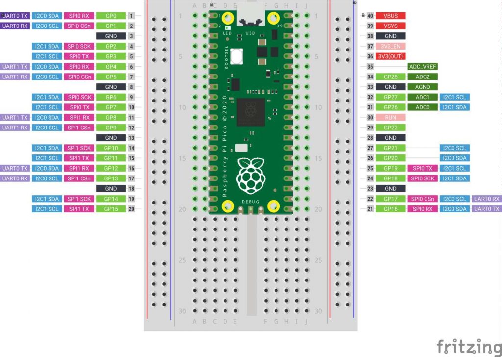
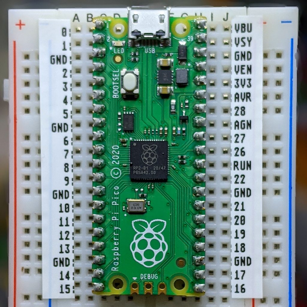
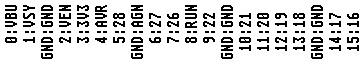
Nothing particularly new or innovative here, but if you’re making simple Raspberry Pi Pico circuits and need to explain them to folks, this little Fritzing template might help. It’s mashed up from:
Since both of these components are from the Raspberry Pi Foundation’s Getting Started documentation, it’s supplied under the same licence.
 Yes, it’s a very tiny microcontroller board and breadboard doohickey. The board’s a Trinket M0 running CircuitPython 2.0. The base is laser-cut birch ply. Definitely #smol at less than 75 × 55 mm …
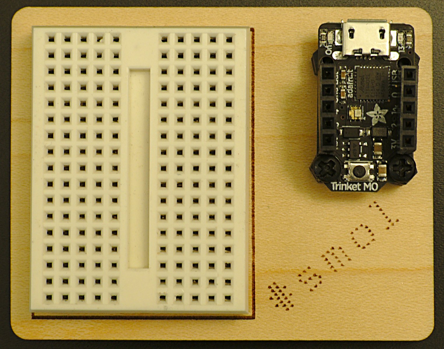 Here’s the SVG for laser cutting:
 To build it, you’ll need:
If I were to redesign this, I’d:
Obligatory blinky code for running a 16 LED NeoPixel Ring and the LED in the middle of the Trinket:
I’m pretty new to Arduino, and electronics in general. Sure, I used to wire up sensors to a bunch of dataloggers, but there wasn’t much variation or application of theory. I made up a bunch of Ardweenies, mostly to practice soldering skills, but now I’ve made them, I might as well use them.

The Ardweeny is a tiny broadboard-only Arduino-compatible microcontroller board. It needs both a power supply and a means of programming it. Solarbotics’ own Breadboard Voltage Regulator Kit provides the juice, while a SparkFun’s FTDI Basic Breakout handles the USB serial programming. The FTDI breakout board can supply power, so I turn the power off to the board at the regulator when programming it. You can’t use shields with the Ardweeny, but it’s small enough that you can have a simple project on a small breadboard. It communicates with the Arduino IDE as if it were a Duemilanove.
 The Ardweeny has pins clearly (if tinily) marked by function. To power it, you need to feed GND and +. The familiar A0-A5 and D0-D13 are present, if not quite where you’d expect them. There isn’t room to mark the digital pins capable of PWM.
For no particular reason (perhaps that spring finally looks like it might be warming things up around here) I wanted to make a a temperature sensor that would sample the temperature at start up, then warn if the temperature got more than 2°C hotter or colder.
I used an LM35 as the sensor. These are a bit noisy, so I added some smoothing (nicked, with little grace, from the Arduino – Smoothing tutorial). The temperature is indicated by three LEDs: red for ≥2°C over, amber for within ±2°C of the starting temperature, and green for ≥2°C under. I also wanted all the LEDs lit while the system was working out starting temperature. Here’s how it runs:


I put the LM35 on A0, and the red, amber and green LEDs on D5, D6 & D8. The only reason I didn’t use D7 was that I didn’t have the right length jumper wire. 680Ω resistors are used to limit current through the LEDs.
Here’s the code:
/*
 lm35_plusminus - read temperature at startup then light
 leds if over or under

 lm35 - analogue 0

 red led - digital 5
 amber led - digital 6
 green led - digital 8

 scruss - 2011-02-17
 */

#define REDPIN 5
#define AMBERPIN 6
#define GREENPIN 8
#define TEMPPIN 0 // analogue
#define DELTA 2.0 // amount +/- from start to warn
#define READINGS 15

//declare variables
float tempC, start_temp, array[READINGS], total;
int val, i;

void setup()
{
  pinMode(REDPIN, OUTPUT);
  pinMode(AMBERPIN, OUTPUT);
  pinMode(GREENPIN, OUTPUT);

  // signal start of test by lighting all LEDs
  digitalWrite(REDPIN, HIGH);
  digitalWrite(AMBERPIN, HIGH);
  digitalWrite(GREENPIN, HIGH);

  // read initial values
  for (i=0; i< READINGS; i++) {
    delay(500/READINGS); // just so initialization is visible
    val = analogRead(TEMPPIN);
    array[i] =  (5.0 * (float) val * 100.0)/1024.0;
    total += array[i];
  }
  start_temp = total / READINGS;

  // test off, lights off
  digitalWrite(REDPIN, LOW);
  digitalWrite(AMBERPIN, LOW);
  digitalWrite(GREENPIN, LOW);
  i=0; // just to initialize
}

void loop()
{
  // some cheapo smoothing copied from the Smoothing example
  //  in the playground
  total -= array[i];
  val = analogRead(TEMPPIN);
  tempC = (5.0 * (float) val * 100.0)/1024.0;
  array[i] = tempC;
  total += tempC;
  i++;
  if (i>=READINGS) {
    i=0;
  }
  tempC = total/READINGS;
  if (tempC - start_temp >= DELTA) {
    // we're hot !
    digitalWrite(REDPIN, HIGH);
    digitalWrite(AMBERPIN, LOW);
    digitalWrite(GREENPIN, LOW);
  }
  else if (tempC - start_temp <= -DELTA) {
    // we're cold !
    digitalWrite(REDPIN, LOW);
    digitalWrite(AMBERPIN, LOW);
    digitalWrite(GREENPIN, HIGH);
  }
  else {
    // we're just right !
    digitalWrite(REDPIN, LOW);
    digitalWrite(AMBERPIN, HIGH);
    digitalWrite(GREENPIN, LOW);
  }
}
Despite the smoothing, the LEDs flicker briefly as they turn on. I kind of like the effect, so I made no attempt to change it.
What I like about Arduino is that — within the limits of my sensor knowledge — the programming language does what I expect. The above program worked first time; worked, that is, save for me putting one LED in the wrong way round, so it didn’t light. I know I could probably replicate the same function with a few linear devices and other components, but it would take much more time and effort. It may not be the most elegant, but it does work, and gives me the satisfaction of the desired result quickly.