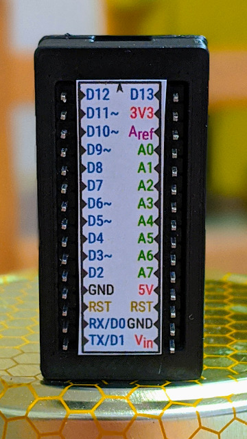
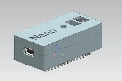
I like Arduino Nanos. They’re cheap. They work. They’re small. But they’re a bit fiddly, what with their breadboard legs and tiny pin labels. Wouldn’t it be nicer to use them as self-contained units, with Dupont wires coming from the pins?
Audio can be a bit dismal on a Raspberry Pi. Once you get a configuration that works, sometimes you’re not sure how you got there and you’ll do anything to keep that arcane setup going. It’s better than it was.
Speech synthesis or TTS adds an extra layer for potential failure. One of the popular Linux TTS systems, eSpeak, hasn’t seen much development in almost a decade and seems to only work through workarounds and hand-waving.
Thankfully, there’s a fork of eSpeak that is maintained: espeak-ng. Better yet, it’s packaged with Raspberry Pi OS and can be installed quite easily:
In my simple tests, it output everything I expected of it.
eSpeak had a Python module that kinda worked, but espeak-ng’s is much more ambitious, and (mostly) does what it sets out to do. You can install it like this:
sudo pip3 install py-espeak-ng
py-espeak-ng has some documentation, but it’s still got some trial and error in getting it to work. The biggest issue that held me up was that the module needs to be initialized with a voice that espeak-ng already knows about. If you don’t specify a voice, or specify one that the system doesn’t know about, you won’t get any errors — but you won’t get any output, either.
Here’s a small Python example that you’ll probably want to try with no-one else within earshot. It repeats the same English phrase (a favourite of elocution teachers) in every English regional language that espeak-ng knows about. In addition, since I’m a dictionary nerd, it outputs phonetics too.
#!/usr/bin/python3
# -*- coding: utf-8 -*-
# an espeakng elocution lesson from scruss, 2020-07
#     I suffered this at school, now you get to as well!
# You will need to:
#     sudo apt install espeak-ng espeak-ng-data libespeak-ng-dev
#     sudo pip3 install py-espeak-ng

from espeakng import ESpeakNG
from time import sleep

# you have to initialize with a voice that exists
#   `espeak-ng --voices=en` will list English ones
esng = ESpeakNG(voice='en-gb')
esng.pitch = 32
esng.speed = 150

phrase = "Father's car is a Jaguar and pa drives rather fast. "\
    "Castles, farms and draughty barns, all go charging past."
print(phrase)
print()

for voice in esng.voices:
    if voice['language'].startswith('en-'):
        print('Using voice:', voice['language'],
              'for', voice['voice_name'], '-')
        esng.voice = voice['language']
        ipa = esng.g2p(phrase, ipa=2)
        print(voice['language'], 'phonetics:', ipa)
        esng.say(phrase, sync=True)
        print()
        sleep(0.1)
Be thankful you can’t hear the output. The IPA output, however, is a thing of beauty:
./espeakNG_test.py
Father's car is a Jaguar and pa drives rather fast. Castles, farms and draughty barns, all go charging past.
Using voice: en-029 for English_(Caribbean) -
en-029 phonetics: fˈɑËdaz kˈɑ͡əɹ ɪz a d͡ʒˈaÉ¡wÉ‘Í¡É™ and pËˆÉ‘Ë dɹˈa͡ɪvz ɹˈɑËda fˈaÍ¡astkˈaÍ¡asÉ›lzfˈɑ͡əmz and dɹˈaÍ¡afti bˈɑ͡ənzˈɔËl É¡ËŒoÍ¡ÊŠ t͡ʃˈɑ͡əd͡ʒɪn pˈaÍ¡ast
Using voice: en-gb for English_(Great_Britain) -
en-gb phonetics: fˈɑËðəz kˈɑËɹ ɪz É d͡ʒˈaÉ¡wÉ‘Ë and pËˆÉ‘Ë dɹˈa͡ɪvz ɹˈɑËðə fˈastkˈasə͡lzfˈɑËmz and dɹˈafti bˈɑËnzˈɔËl ɡˌə͡ʊ t͡ʃˈɑËd͡ʒɪŋ pˈast
Using voice: en-gb-scotland for English_(Scotland) -
en-gb-scotland phonetics: fˈa:ðɜz kˈaËr ɪz É d͡ʒˈaÉ¡waËr and pˈa: drˈa͡ɪvz rˈa:ðɜ fˈa:stkˈa:sə͡lzfˈaËrmz and drˈa:fte bˈaËrnzˈɔËl É¡ËŒoË t͡ʃˈaËrd͡ʒɪŋ pˈa:st
…
How many CPU hours did I burn in the early 1990s rendering bits of the Mandelbrot Set? A lot, mainly because I was doing it in BASIC on an unexpanded 8 MHz Commodore Amiga A500. The image below that Fraqtive rendered in almost no time would have taken me days:
the squashed bug that started it all: the Mandelbrot set
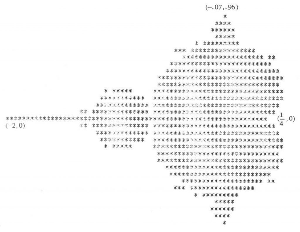
But it turns out that the first rendering of what we now call the Mandelbrot set wasn’t produced by Benoit Mandelbrot, but by Brooks & Matelski a year or two earlier:
figure 2 (original caption “The set of C’s such that f(z) = z² + C has a stable periodic orbit“) from Brooks, Robert, and J. Peter Matelski. “The dynamics of 2-generator subgroups of PSL (2, C).” Riemann surfaces and related topics: Proceedings of the 1978 Stony Brook Conference, Ann. of Math. Stud. Vol. 97. 1981.
What I’ve done – and mostly thanks to tweaks by commenter nobody below – is create period-appropriate code to reproduce that graphic. Since the paper was presented in 1978, there’s a fair chance that the authors had access to a machine running FORTRAN-77 or a near equivalent. FORTRAN’s particularly good for this:
it has a built-in COMPLEX type that extends regular mathematical functions;
it has just good enough string handling to output a line of spaces/asterisks. I would not have wanted to write this in FORTRAN-66, as that language had no string manipulation facilities atall.
So here’s the code. It should compile on any Fortran compiler:
      PROGRAM BRKMTF
!     GENERATE FIGURE FROM BROOKS-MATELSKI PAPER C.1978
!     THAT EVENTUALLY BECAME KNOWN AS THE MANDELBROT SET
!     - SCRUSS, 2022-05
!     REF: BROOKS, ROBERT, AND J. PETER MATELSKI.
!     "THE DYNAMICS OF 2-GENERATOR SUBGROUPS OF PSL (2, C)."
!     RIEMANN SURFACES AND RELATED TOPICS: PROCEEDINGS OF THE
!     1978 STONY BROOK CONFERENCE,
!     ANN. OF MATH. STUD. VOL. 97. 1981: FIG. 2, P. 81

      REAL MAP, CR, CI
      INTEGER I, J, K, M, ROWS, COLS, MAXIT
      COMPLEX C, Z
      PARAMETER (ROWS=31, COLS=71, MAXIT=200)
      CHARACTER*80 OUT
      CHARACTER CH*1

      DO J=1,ROWS
         CI=MAP(REAL(J), 1.0, REAL(ROWS), -0.8715, 0.8715)
         DO I=1,COLS
            CR=MAP(REAL(I), 1.0, REAL(COLS), -1.975, 0.475)
            C=CMPLX(CR, CI)
            Z=CMPLX(0.0, 0.0)
            CH='*'
            DO 100, K=1,MAXIT
               Z = Z**2 + C
               IF (ABS(Z) .GT. 2) THEN
                  CH=' '
                  GO TO 101
               END IF
 100        CONTINUE
 101        OUT(I:I)=CH
         END DO
         WRITE(*,*)OUT
      END DO
      END

      REAL FUNCTION MAP(X, XMIN, XMAX, YMIN, YMAX)
      REAL X, XMIN, XMAX, YMIN, YMAX
      MAP = YMIN + (YMAX - YMIN) * ((X - XMIN) / (XMAX - XMIN))
      END
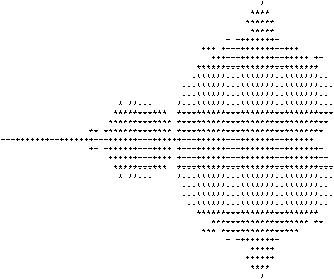
The results are spot-on:
party like it’s ’78
Maybe Brooks & Matelski had access to an Apple II and wrote something in BASIC? I could be entirely period-accurate and write something in PDP-8 BASIC on my SBC6120, but not today.
It really is much easier using a language with complex number support when working with the Mandelbrot set. Here’s the same program in Python3, which bears more of a resemblance to FORTRAN-77 than it might admit:
#!/usr/bin/python3
# brkmtf - Brooks-Matelski proto ASCII Mandelbrot set - scruss, 2022-05
# -*- coding: utf-8 -*-

def valmap(value, istart, istop, ostart, ostop):
    return ostart + (ostop - ostart) * ((value - istart) / (istop - istart))

rows = 31
cols = 71
maxit = 200

for y in range(rows):
    ci = valmap(float(y + 1), 1.0, float(rows), -0.8715, 0.8715)
    for x in range(cols):
        cr = valmap(float(x + 1), 1.0, float(cols), -1.975, 0.475)
        c = complex(cr, ci)
        z = complex(0.0, 0.0)
        ch = '*'
        for k in range(maxit):
            z = z**2 + c
            if (abs(z) > 2.0):
                ch = ' '
                break
        print(ch, end='')
    print()
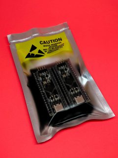
Volker Forster at Universal Solder was kind enough to send me a couple of these boards for free when I asked about availability. By way of thanks, I’m writing this article about what’s neat about these micro-controller boards.
always neat packaging from Universal Solder
Can I just say how nicely packaged Universal Solder’s own or customized products are? They want it to get to you, and they want it to work.
I’d previously played around with Blue Pill and Black Pill boards with limited success. Yes, they’re cheap and powerful, but getting the toolchain to work reliably was so much work. So when I read about the WeAct STM32F411CEU6 board on the MicroPython forum, I knew they’d be a much better bet.
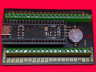
Canaduino Black Pill Carrier Board with STM32F411 (and battery) installed
Let’s start with the STM32 Screw Terminal Adapter:
Canaduino Black Pill Carrier Board (front)
It’s a neat, solid board built on a black 1.6 mm thick PCB. Apart from the obvious screw terminals — essential for long-term industrial installations — it adds three handy features:
a real-time clock battery. If you’re using a micro-controller for data logging, an RTC battery helps you keep timestamps accurate even if the device loses power.
mounting holes! This may seem a small thing, but if you can mount your micro-controller solidly, your project will look much more professional and last longer too.
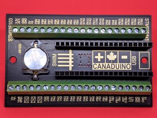
A 6–30 V DC regulator. Connect this voltage between Vin and GND and the regulator will keep the board happy. From the helpful graph on the back of the board, it doesn’t look as if things start getting efficient until around 12 V, but it’s really nice to have a choice.
Canaduino Black Pill Carrier Board (back)
I made a little slip-case for this board so it wouldn’t short out on the workbench. The project is here: Canaduino STM32 Screw Terminal board tray and you can download a snapshot here:
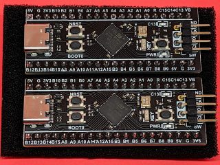
Gone are the lumpy pin headers of the earlier Blue and Black Pill boards, replaced by tactile switches. The iffy micro USB connectors are replaced by much more solid USB C connectors. According to STM32-base, the STM32F411 has:
100 MHz ARM Cortex-M4 core. This brings fast (single-precision) floating point so you don’t have to fret over integer maths
512 K Flash, 128 K RAM. MicroPython runs in this, but more flash is always helpful
Lots of digital and analogue I/O, including a 12-bit ADC
A user LED and user input switch.
About the only advanced features it’s missing are a true RNG, a DAC for analogue outputs, and WiFi. But on top of all this, Volker added:
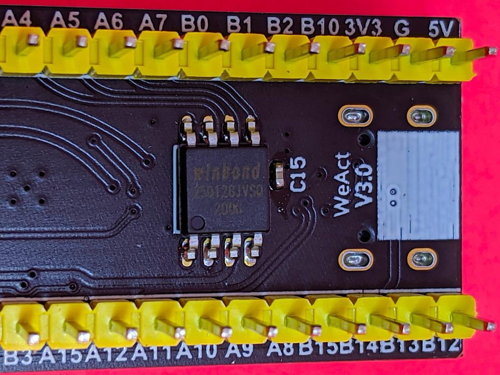
the all-important 128 Mbit flash chip (and capacitor) fitted by Universal Solder
128 Mbit of Flash! This gives the board roughly 16 MB of storage that, when used with MicroPython, appears as a small USB drive for your programs and data. I found I was able to read the ADC more than 22,000 times/second under MicroPython, so who needs slow-to-deploy compiled code?
I had to run make a couple of times before it would build, but it built and installed quickly. This board doesn’t take UF2 image files that other boards use, so the installation is a little more complicated than other. But it works!
Once flashed, you should have a USB device with two important MicroPython files on it: boot.py and main.py. boot.py is best left alone, but main.py can be used for your program. I’m going into more details in a later article, but how about replacing the main.py program with the fanciest version if Blink you ever saw:
# main.py -- fancy Blink (scruss, 2020-05)

from pyb import LED
from machine import Timer
tim = Timer(-1)
tim.init(period=1000, mode=Timer.PERIODIC,
         callback=lambda t: LED(1).toggle())
None of that blocking delay() nonsense: we’re using a periodic timer to toggle the user LED every second!
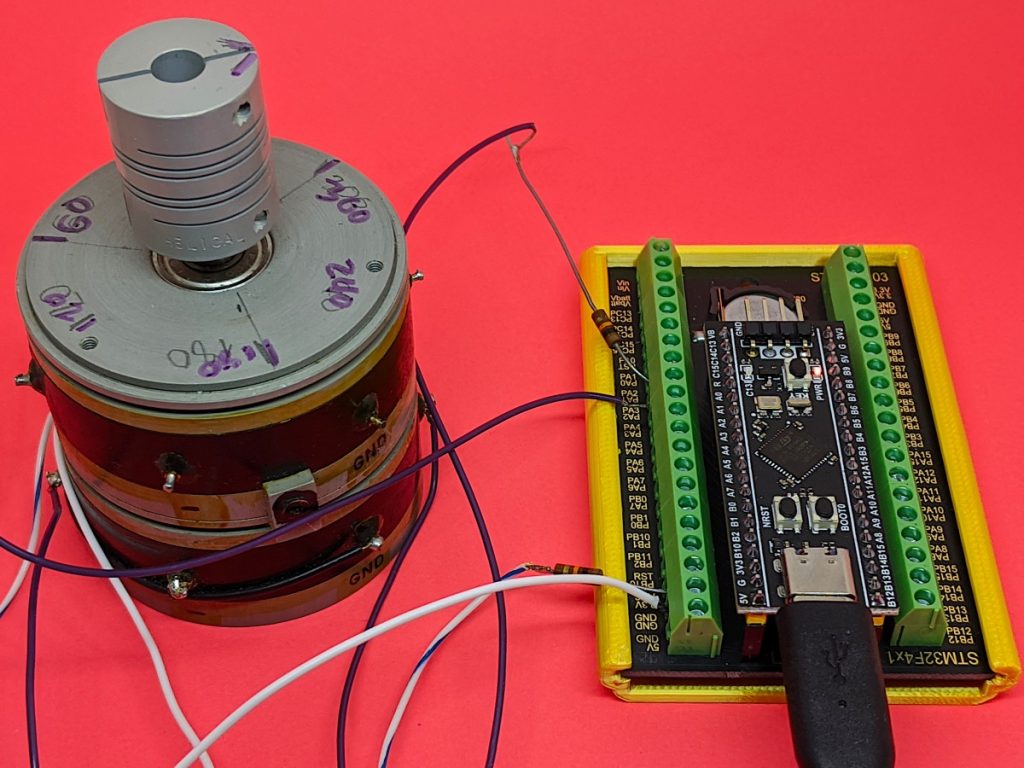
debugging the mystery huge potentiometer using two ADC channels
I’m really impressed with the Universal Solder-modified board as an experimentation/discovery platform. MicroPython makes development and testing really quick and easy.
[and about the mystery huge potentiometer: it’s a Computer Instruments Corporation Model 206-IG multi-turn, multi-track potentiometer I picked up from the free table at a nerd event. I think it’s a 1950s (so Servo-control/Cybernetics age) analogue equivalent of a shaft encoder, looking at the patent. Best I can tell is that each pot (there are two, stacked, with precision bearings) appears to have two 120° 10k ohm sweep tracks offset 90° to one another. The four wipers are labelled -COS, -SIN, +COS and +SIN. If anyone knows more about the thing, let me know!]
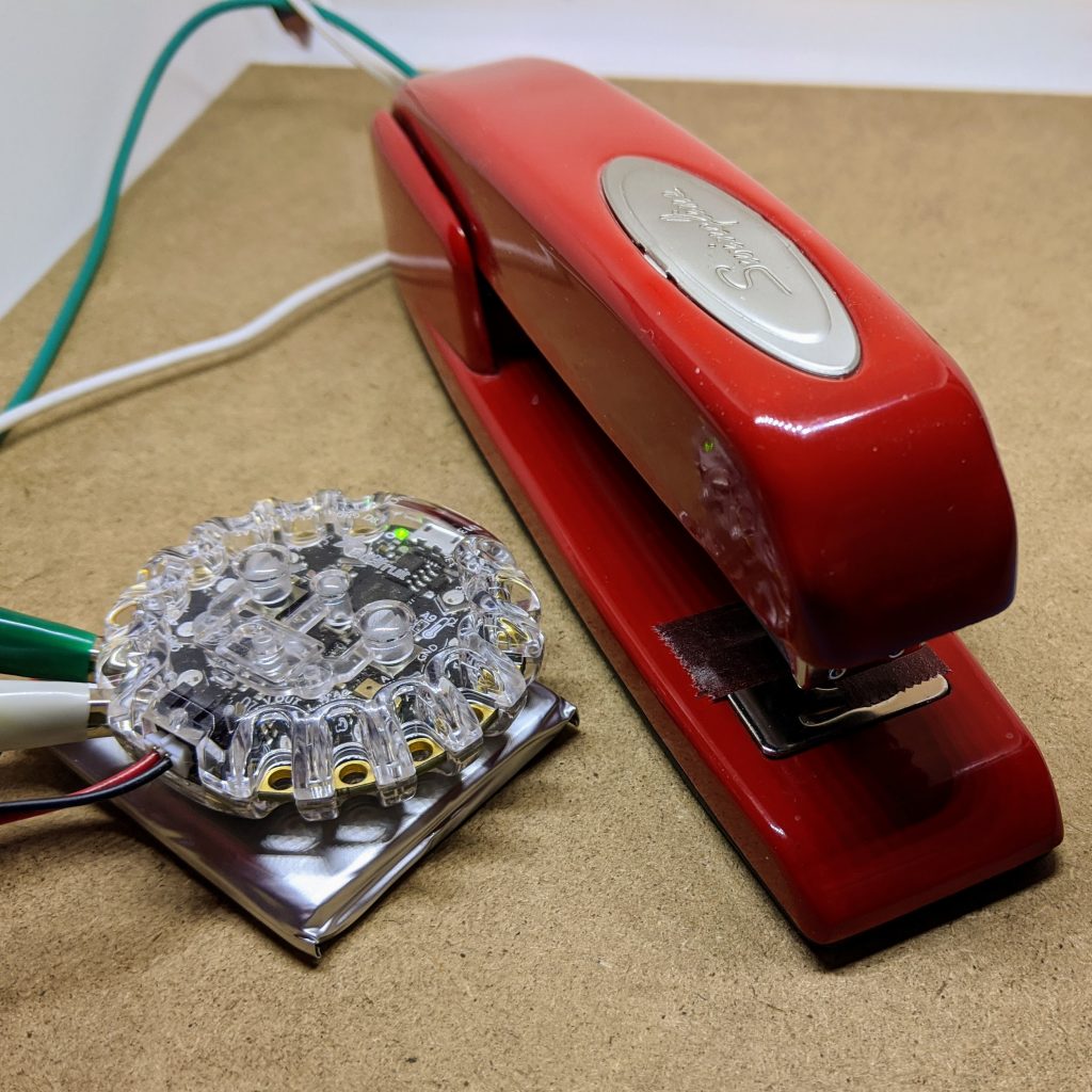
The important thing about a switch is that it has two electrically isolated parts that come together to close a circuit. And that’s exactly what the Swingline® 747® stapler doesn’t have: its entire metal body and mechanism is electrically conductive. So we have to rig something up …
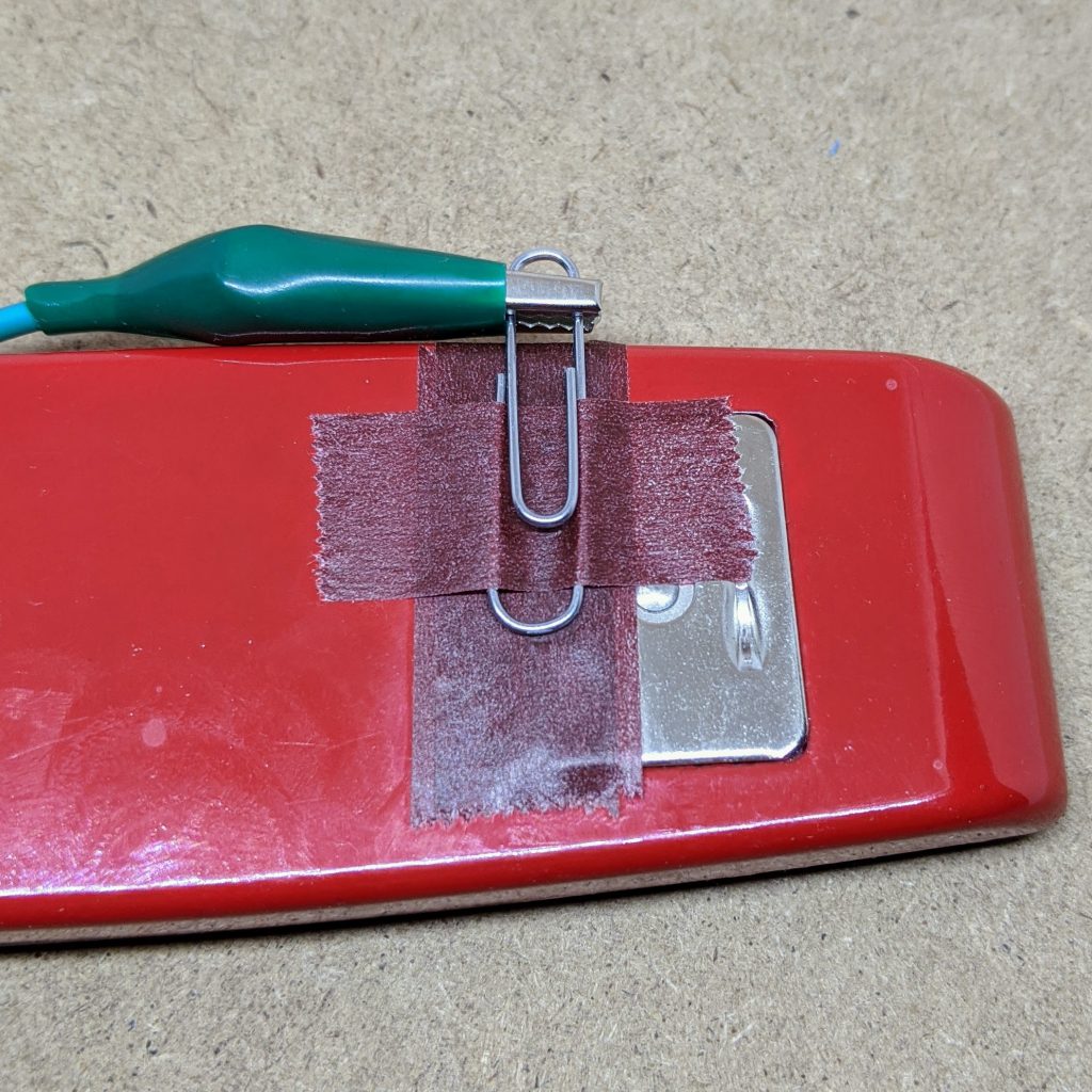
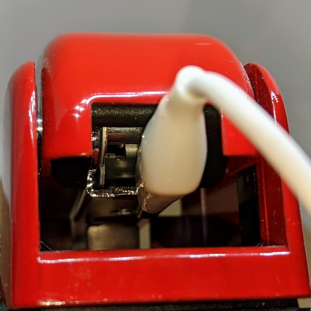
Tape, paperclip and alligator clip make up one half of the switch… while a handy ledge at the back of the staple dispenser provides a connection for alligator clip #2
Did I say take the staples out yet? No? Take the staples out of the stapler. Possibly even before doing anything else.
The code we’re going to run on the Circuit Playground Express is very simple:
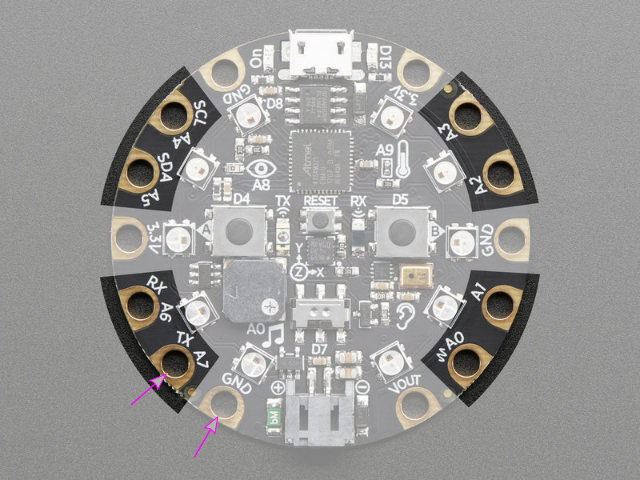
Set up pin 1 (helpfully named A7 on the board) as an input. Turn off all the LEDs
If pin 1 is shorted to ground, increase a counter and light successive numbers of LEDs round the CPX’s face
If the counter reaches 10, play the sample, reset the counter and turn off all the LEDs
repeat from “If pin 1 is shorted to ground …” until too bored to continue.
Here’s the code:
# SIM-SimStapler / RealStapler - scruss, 2020-04
# circuitpython on CPX - stapler between D1 (A7) and GND

from adafruit_circuitplayground import cp
import board
from digitalio import DigitalInOut, Direction, Pull
import time

# set up stapler on pin D1 (port A7): goes LOW when pressed
stapler = DigitalInOut(board.D1)
stapler.direction = Direction.INPUT
stapler.pull = Pull.UP

# set up pixels - not too bright
cp.pixels.brightness = 0.1
# turn all pixels off
for i in range(10):
    cp.pixels[i] = (0, 0, 0)

count = 0
while True:
    # stapler pressed, so increase count
    if not stapler.value:
        count = count + 1
        # only count first press, not if held
        while not stapler.value:
            pass
        time.sleep(0.1)

    # light up pixels clockwise for each press
    for i in range(count):
        cp.pixels[9 - i] = (0, 255, 0)

    # get a bonus Penelope Keith every ten presses
    if count == 10:
        cp.play_file("splendid.wav")
        # turn all pixels off after bonus
        for i in range(count):
            cp.pixels[i] = (0, 0, 0)
        # and reset counter for next time
        count = 0
Here’s the code and sample ready to be copied to your CIRCUITPYTHON drive:
(The sample is a slightly tweaked version of Freeverse’s original Bonus.wav. I ran it through an equalizer to make it sound less awful through the CPX’s tinny little speaker. I was also today years old when I found out that the sample wasn’t Penelope Keith from To the Manor Born, but Jen Krasinski, a staffer at Freeverse.)
The connection (singular) is simple:
Alligator clips to A7 (in reality, D1) and GND
Have an appropriate amount of fun!
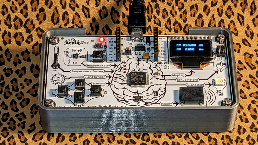
I suppose I could also have done this on the BrainPad, but I haven’t set it up with MicroPython yet, and I don’t have time to drag coding blocks around. Also, this is not any project to associate with the word “brain” …
(since Thingiverse’s markdown parser seems to be broken)
Summary
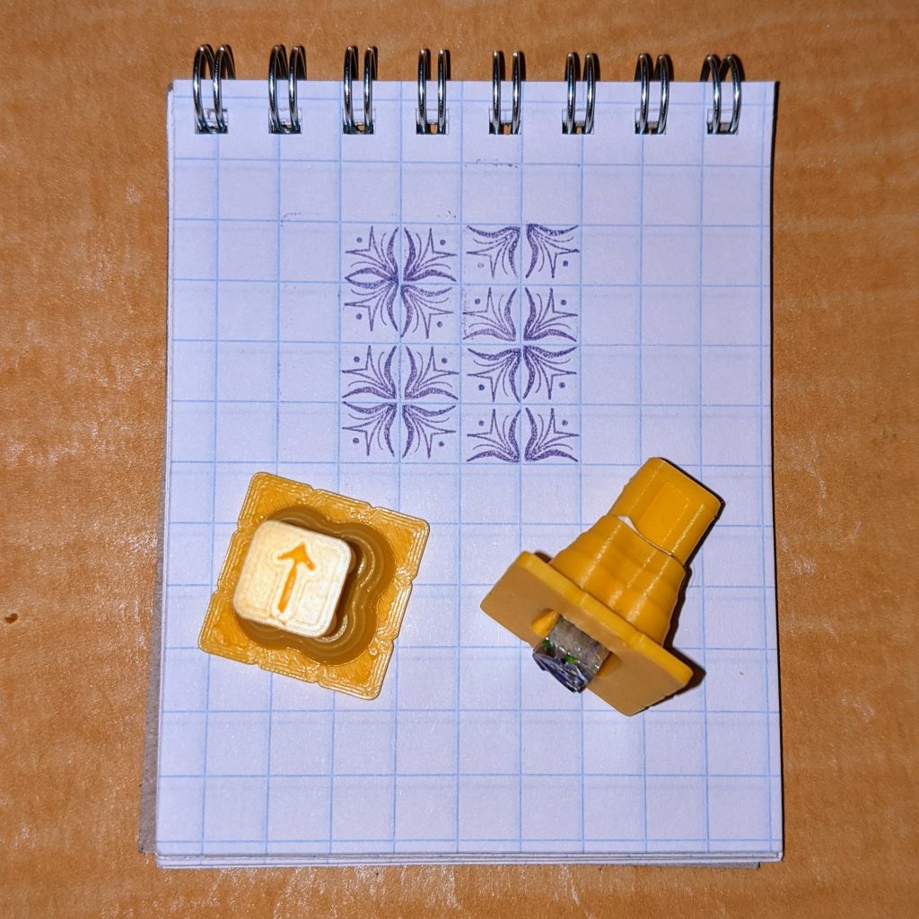
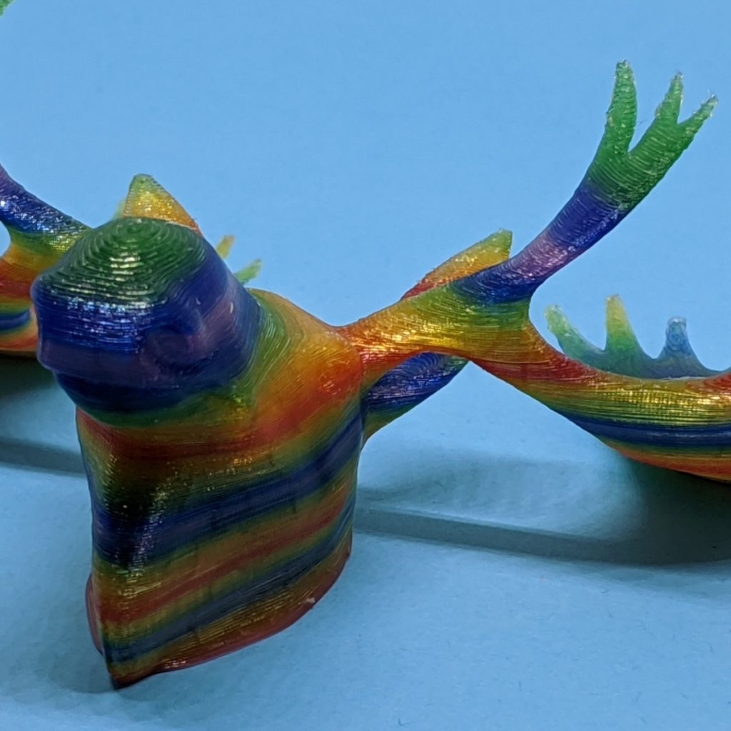
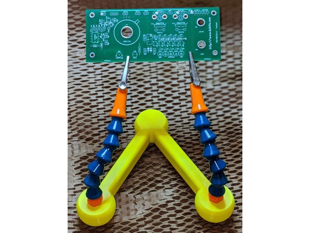
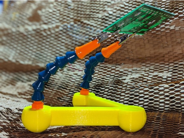
A weighted, non-slip, non-wobble soldering third hand.
Huge thanks to Modular Hose for giving me the Loc-Line samples I used to make this!
Why is it called TRex? It’s got really short arms …
Despite what Thingiverse might say, this is not a Customizer project. Opening that link will disappoint.
Parts required
at least 12× ¼” Loc-Line segments
2× Loc-Line ¼” NPT threaded connectors
2× Loc-Line ¼” nozzles
2× alligator clips
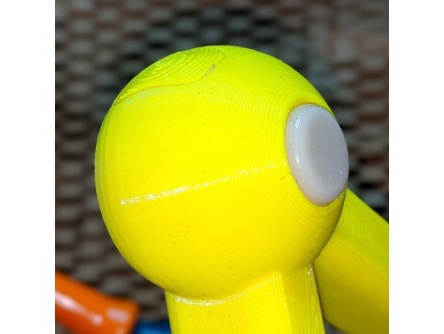
3× adhesive round non-slip feet (up to 16 mm diameter)
appx. 60 g steel BB shot (or available equivalent) as ballast
hot glue to secure ballast and seal port in place
Polycaprolactone (PCL; trade names include InstaMorph) warm-melt granules to secure clips into nozzles
(optional) PTFE plumber’s tape.
Note that Modular Hose promotional Loc-Line keyrings each have 3 segments plus a threaded connector and nozzle, so four keyrings provide enough parts.
Assembly
assemble the two Loc-Line arms with a threaded connector and at least six segments each
secure the ends of the alligator clips in the nozzles using softened PCL or hot glue. Make sure that the ball joint connector surface is clear of material, as you’ll need this to fit the nozzle onto the arm
fill the tool body with ballast, apply a plug of hot glue to stop it rattling and secure the end port in place
Carefully thread the arms onto the tool body. NPT threads are tapered, so become gradually tighter as they go in. Use a little plumber’s tape if they’re too loose. Be careful not to overtighten, as this might crack the tool
Apply the non-slip feet, applying appropriate pressure to activate the adhesive
Hey! This is really old! FreeCAD 0.19 is in the Raspberry Pi OS Bullseye repo now:
sudo apt install freecad
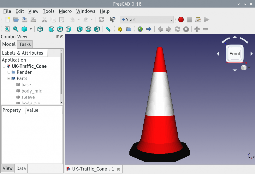
FreeCAD 0.18.4 running on a Raspberry Pi 4
FreeCAD and the Raspberry Pi haven’t always got on too well. For complex technical reasons the standard package would load and immediately crash on a Raspbian system. For user reasons, this was just another annoyance.
Recent releases seem to run fairly well on a Raspberry Pi 4, though, but only after building them from source. Here’s a method that got FreeCAD 0.18.4 running for me. It’s lightly modified from FreeCAD forum MartijnD‘s post:
The only modifications I made to Martijn’s method were in the Python paths in the cmake command. Some of the paths given aren’t valid any more on an up-to-date Buster system
I built this on a Raspberry Pi 4 with 4 GB of RAM. It takes quite a bit of free storage: I wouldn’t attempt to build this with less than 4 GB free
make -j4 took 95 minutes, and even with a fan my Raspberry Pi 4 was at 70°C
Yes, it’s using Python 2.7, but it works
I’ve got no idea how to make it install properly, but it runs from the freecad-build/bin directory.
If you want to learn how to use it, look at the tutorials: even the Raspberry Pi Foundation have written some. The UK Traffic Cone model you can have: it’s what I made to learn a bit more about FreeCAD. Don’t worry, I’m still on Team OpenSCAD …
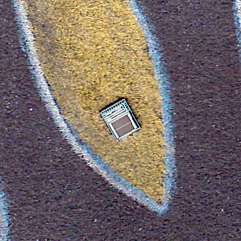
CBC says that Alberta’s looming multibillion-dollar orphan wells problem prompts auditor general probe. I mean, I’d say it does: estimated costs to clean up abandoned petrochemical wells outstrip the industry cleanup fund by over 132×, so it’s gone way past looming and is well into omnishambles country. But I’m not here to talk about the environmental mismanagement (well, not much: lolRedwater …), but more to talk about CBC’s terrible infographic:
Total estimated liabilities: $30.1 billion; Total security held: $227 million. It doesn’t take Wilkins Micawber to tell you that the result is misery
The image is accurate, technically. The estimated liabilities ($30100000000) are 132.6× the total security held ($227000000), and the red square’s length is 11½× (= √132.6) the blue one’s. But people are generally terrible at comparing areas.
Here are the same numbers, but in bar chart form:
They’re not even on the same page, are they? (Graph badly put together by me in netpbm. Yes, netpbm …)
And there’s the problem: it’s too big to comprehend. CBC’s comfortable little chart fits on a page; you can tweet it, even. But reality is a whole lot of scrolling down the page.
Even the manky old pie chart would be better than CBC’s squares-by area:
Securities are a 2.69° wedge. Liabilities, the rest
At least pie charts used linear measure as a proportion of the full 360° pie. But comparing areas is hard; in the diagram below, the teal-coloured part is twice the area of the gold part.


![[french/piedmnotese dictionary text]
Scruss s.; Bruit, fracas, cri.
La porta a la fait un scruss;
La porte a crié, a fait un cri.](https://scruss.com/wordpress/wp-content/uploads/2020/02/piedmontese-scruss.png)