Modding an Adafruit PIR for 3.3 volts

green circuit board covered in surface mount components. A grey wire has been soldered to the output pin of the SOT-89 package 7133-1 voltage regulator
slightly dodgy soldering of a grey jumper wire to the Vout pin of the PIR’s voltage regulator

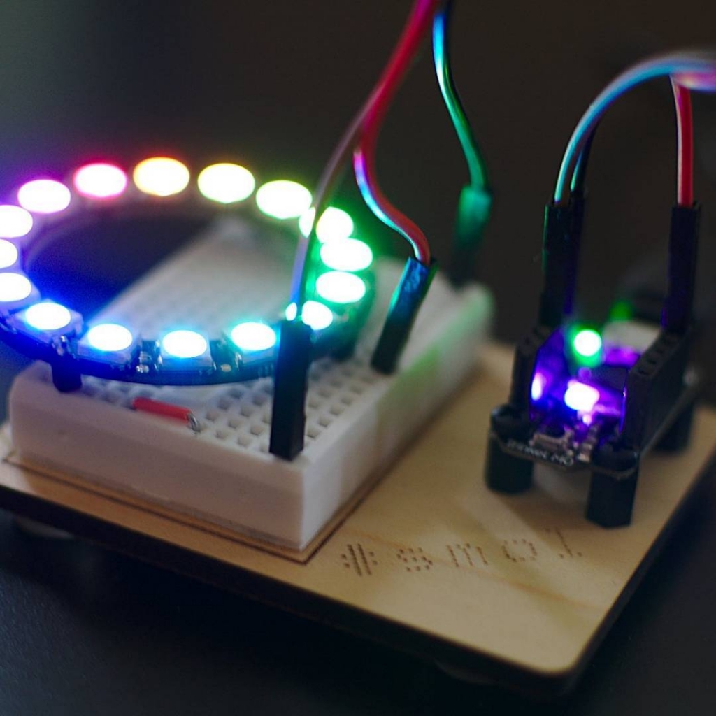
Consider the Adafruit PIR (motion) sensor (aka PIR Motion Sensor, if you’re in Canada). Simple, reliable device, but only runs from a 5 V supply. Yes, there are smaller PIRs that run off 3.3 V, but if this is what you have, you need to do some soldering. Annoyingly, the sensor on the board is a 3.3 V part, but the carrier was designed in Olden Tymes when King 5 V ruled.

You can try powering it from 3.3 V, but it’ll go all off on its own randomly as its own power supply won’t be supplying enough voltage. There are a couple of sites on how to modify these PIRs that either describe old kit you can’t get any more, or do it completely wrongly. Just one post on the Adafruit support forum gets it right.

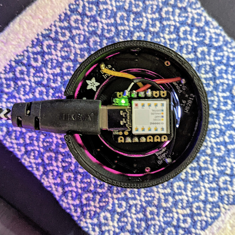
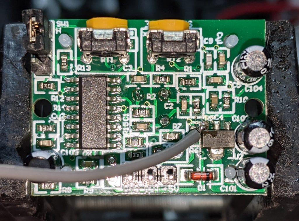
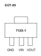
One way of doing this is to provide 3.3 V directly to the output pin of the voltage regulator, and ignore the 5 V power line entirely. The regulator’s a SOT89-3 part that looks a bit like this:

71xx-1 SOT-89 package outline, with three pins at the bottom and one large ground tab (connected to centre pin, but not visible) at the top
wee leggy thing

In the photo above, it’s flipped over. Whichever way it’s oriented, we want to put power directly into the Vout pin. There may be easier points to solder this to than a tiny surface mount pin (almost definitely one of the capacitors) but this has held for me.

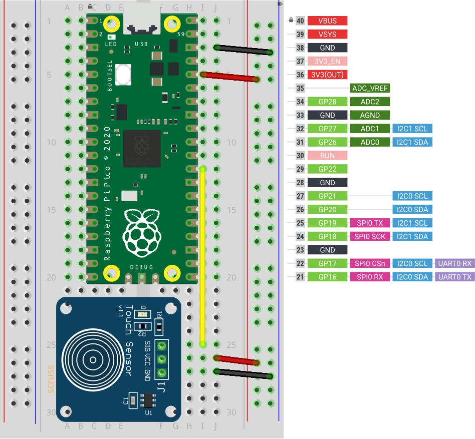
How to use it in MicroPython? Like the TTP223 capacitive touch sensors I looked at before, a PIR gives a simple off/on output, so you can use something like this:

from machine import Pin
from time import sleep_ms

pir = Pin(21, Pin.IN)

while True:
    print("[", pir.value(), "]")
    sleep_ms(1000)

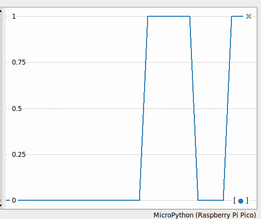
value() will return 1 if there’s movement, 0 if not. There are trigger time and sensitivity potentiometers to fiddle with on the board if you need to tweak the output.

line graph showing output signal going from 0 to 1, back down to 0 and ending at one over a period of about 20 seconds
Thonny plotter output showing a couple of movement detections. High output (on my device) stays up for about 4 seconds, so you can be pretty leisurely about polling PIRs

Just remember: don’t connect the 5 V power line if you make this mod. I’m not responsible for any smoke emitted if you do — but I can always sell you a replacement …

Lentil Soup

Ingredients

  • 6 cups vegetable stock (or 3 veggie stock cubes + 6 cups water)
  • 3-4 medium onions, chopped roughly
  • 4-6 medium carrots; half chopped roughly, half grated
  • 2 cups red split lentils
  • 4-6 tbsp olive oil
  • 2 tbsp baking soda (for soaking lentils)

Optional ingredients

  • 1 tbsp prepared Dijon mustard
  • 1 tbsp sweet paprika

Lentil Preparation

  • Rinse and drain lentils at least three times: they should no longer clump, and rinse water should not be very cloudy
  • Soak lentils in water with baking soda for at least an hour, occasionally stirring gently
  • Rinse lentils and soak for at least an hour in clean water; drain.

Method

  1. Bring stock to a boil in a large pot. Add grated/chopped carrots and half the olive oil
  2. Fry onions in the rest of the olive oil until translucent, optionally with paprika
  3. Add fried onions to soup pot. Stir in Dijon mustard, if desired
  4. Cover and allow to low boil for 5-10 minutes
  5. Stir in drained lentils, and bring to a robust simmer
  6. Cover and simmer for 15 minutes.
  7. Serve and season to taste.

Notes

  • This is based on my parents’ various lentil soup recipes from Scotland. They might use a ham or lamb-bone based stock
  • Until recently, I’d been overcooking the lentils. Red split lentils are quite delicate, and soaking and lightly simmering gives a pleasing result
  • The soaking in baking soda stage helps to de-gas the lentils

Raspberry Pi Pico with TTP223 Touch Sensor

This is almost too trivial to write up, as the TTP223 does exactly what you’d expect it to do with no other components.

breadboard with Raspberry Pi Pico and small blue capacitive touch sensor
TTP223 sensor board connected to GP22 / physical pin 29

Breakout boards for the TTP223 capacitive touch sensor come in a whole variety of sizes. The ones I got from Simcoe DIY are much smaller, have a different connection order, and don’t have an indicator LED. What they all give you, though, is a single touch/proximity switch for about $1.50

Trivial code to light the Raspberry Pi Pico’s LED when a touch event is detected looks like this:

import machine
touch = machine.Pin(22, machine.Pin.IN)
led = machine.Pin(25, machine.Pin.OUT)

while True:
    led.value(touch.value())

For the default configuration, the sensor’s output goes high while a touch is detected, then goes low. This might not be the ideal configuration for you, so these sensor boards have a couple of solder links you can modify:

  1. Active Low — sometimes you want a switch to indicate a touch with a low / 0 V signal. On the boards I have, the A link controls that: put a blob of solder across it to reverse the switch’s sense.
  2. Toggle — if you want the output to stay latched at one level until you touch it again, a blob of solder across the T link will do that. Unlike a mechanical switch, this won’t stay latched after a power cycle, though.

And that’s all it does. Sometimes it’s nice to have a sensor that does exactly one thing perfectly well.

Niche Knowledge: Z80 parallel port SD card on Zeta2

green circuit board with secure digital card slot on left and 40-pin parallel interface connectors on the right
Mini PPISD board: a slow SD card mass-storage system for 8-bit computers

Almost no-one will need this knowledge, but I might need to remember it. In order to add Mini PPISD support to a RomWBW 3.01-supported system, you need to create a file called something like Source/HBIOS/Config/ZETA2_ppisd.asm (for yes, I’m using a Zeta SBC V2) containing:

#include "cfg_zeta2.asm"
UARTCFG		.SET	UARTCFG | SER_RTS
CRTACT		.SET	TRUE		
PPIDEENABLE	.SET	FALSE		
SDENABLE	.SET	TRUE		
PPPENABLE	.SET	FALSE		
PPISD		.EQU	TRUE

Running make from the top-level directory should create a ROM image called Binary/ZETA2_ppisd.rom for you to write to flash. Since my floppy drive isn’t feeling too happy, I had to resort to buying a TL866II Plus programmer to write the chip.

And it worked!

 RomWBW HBIOS v3.0.1, 2021-03-12

 ZETA V2 Z80 @ 8.000MHz
 0 MEM W/S, 1 I/O W/S, INT MODE 2
 512KB ROM, 512KB RAM

 CTC: MODE=Z2 IO=0x20
 UART0: IO=0x68 16550A MODE=38400,8,N,1
 DSRTC: MODE=STD IO=0x70 Sun 2021-03-14 17:47:13 CHARGE=OFF
 MD: UNITS=2 ROMDISK=384KB RAMDISK=384KB
 FD: IO=0x30 UNITS=2
 SD: MODE=PPI IO=0x60 DEVICES=1
 SD0: SDSC NAME=SD    BLOCKS=0x003C7800 SIZE=1935MB

 Unit        Device      Type              Capacity/Mode
 ----------  ----------  ----------------  --------------------
 Char 0      UART0:      RS-232            38400,8,N,1
 Disk 0      MD1:        RAM Disk          384KB,LBA
 Disk 1      MD0:        ROM Disk          384KB,LBA
 Disk 2      FD0:        Floppy Disk       3.5",DS/HD,CHS
 Disk 3      FD1:        Floppy Disk       3.5",DS/HD,CHS
 Disk 4      SD0:        SD Card           1935MB,LBA

 ZETA V2 Boot Loader

 ROM: (M)onitor (C)P/M (Z)-System (F)orth (B)ASIC (T)-BASIC (P)LAY (U)SER ROM  
 Disk: (0)MD1 (1)MD0 (2)FD0 (3)FD1 (4)SD0 

 Boot Selection? 

I was pleasantly surprised how easy it is to use a TL866 programmer under Linux. minipro does all the work, though. To write and verify the whole 512K Flash ROM, it’s:

minipro -p SST39SF040 -w ZETA2_ppisd.rom

The programmer supports over 16000 devices, of which around 10000 are variants (form factor, programming voltage, speed, OTP, etc). It’ll also verify over 100 different 74-series logic chips. It’s not a super cheap device (mine was a little over $80, from Simcoe Diy) but it does a lot for that price.

Next stop: try rebuilding BBC BASIC with RomWBW’s timer support included ..

ZX81 40th Anniversary

So the Z80-powered doorstop that got so many people started with computers was launched 40 years ago.

My story is that we never had one: we had three, but only for a week each. It’s not that they failed, either. My dad, who ran the computer bureau at King George V Docks for the Clyde Port Authority, was Glasgow’s representative on the European Association for Data Processing in Ports (EVHA). The group was looking at ways for automating ship identification, efficient berthing and documentation handling.

All the ports had data centres, but most of the mainframe time was for predefined tasks such as dock-worker payroll. There wasn’t the budget for computer time to try some of the experimental projects that may have helped with port automation.

Several EVHA members were trying home computers unofficially, but many of them were too expensive to come in under expense account rules. These “big” micros required a business case and purchase order to buy. The ZX81, limited as it was, did fit in the expense budget and – equally importantly – fitted into my dad’s suitcase as he made his monthly trips to Europe.

The week before my dad was scheduled to leave, he’d buy a ZX81. Of course, it needed “testing”, something me and my brother were only too happy to do. At the end of the week, it would get packed up and on its way to Europe.

I’m not sure if the clandestine micros were ever actually used for controlling ship traffic (you get considerably fewer than three lives manoeuvring an LNG tanker), but more likely in simulation. I understand that the ZX81 was able to simulate the traffic management for the entire Port of Rotterdam for a while, at least until its RAM pack wobbled.


reposted from ZX81 40th Anniversary – Histories – Retro Computing

Seeeduino XIAO simple USB volume control with CircuitPython

round computer device with USB cable exiting at left. Small microcontroller at centreshowing wiring to LED ring and rotary encoder
Slightly blurry image of the underside of the device, showing the Seeeduino XIAO and the glow from the NeoPixel ring. And yes, the XIAO is really that small

Tod Kurt’s QTPy-knob: Simple USB knob w/ CircuitPython is a fairly simple USB input project that relies on the pin spacing of an Adafruit QT Py development board being the same as that on a Bourns Rotary Encoder. If you want to get fancy (and who wouldn’t?) you can add a NeoPixel Ring to get an RGB glow.

The QT Py is based on the Seeeduino XIAO, which is a slightly simpler device than the Adafruit derivative. It still runs CircuitPython, though, and is about the least expensive way of doing so. The XIAO is drop-in replacement for the Qt Py in this project, and it works really well! Everything you need for the project is described here: todbot/qtpy-knob: QT Py Media Knob using rotary encoder & neopixel ring

I found a couple of tiny glitches in the 3d printed parts, though:

  1. The diffuser ring for the LED ring is too thick for the encoder lock nut to fasten. It’s 2 mm thick, and there’s exactly 2 mm of thread left on the encoder.
  2. The D-shaft cutout in the top is too deep to allow the encoder shaft switch to trigger.

I bodged these by putting an indent in the middle of the diffuser, and filling the top D-shaft cutout with just enough Blu Tack.

Tod’s got a bunch of other projects for the Qt Py that I’m sure would work well with the XIAO: QT Py Tricks. And yes, there’s an “Output Farty Noises to DAC” one that, regrettably, does just that.

Maybe I’ll add some mass to the dial to make it scroll more smoothly like those buttery shuttle dials from old video editing consoles. The base could use a bit more weight to stop it skiting about the desk, so maybe I’ll use Vik’s trick of embedding BB gun shot into hot glue. For now, I’ve put some rubber feet on it, and it mostly stays put.


Hey! Unlike my last Seeed Studio device post, I paid for all the bits mentioned here.

Nyan Cat, except it gets faster — RTTTL on the Raspberry Pi Pico

Raspberry Pi Pico with small piezo speaker connected to pins 23 (ground) and 26 (GPIO 20)
piezo between pins 26 and 23. Sounds a little like this

It was inevitable:

  1. A Raspberry Pi Pico; plus
  2. a tiny piezo PC beeper; plus
  3. MicroPython; plus
  4. dhylands / upy-rtttl; plus
  5. nyancat.rtttl; plus
  6. my unfailing sense of knowing when to stop, then ignoring it

brings you this wonderful creation, which plays the Nyan Cat theme forever, except it gets 20% faster each time. This is weapons-grade annoying (thank’ee kindly), so I’m not going to include a recording here. If you must hear an approximation, paste the RTTTL into Play RTTTL Online and enjoy.

# Raspberry Pi Pico RTTTL example
# nyan cat, but it gets faster
# scruss - 2021-02: sorry, not sorry ...

# Uses rtttl.py from
#  github.com/dhylands/upy-rtttl
# Nyan Cat RTTTL from
#  github.com/KohaSuomi/emb-rtttl/blob/master/rtttl/nyancat.rtttl

from rtttl import RTTTL
from time import sleep_ms
from machine import Pin, PWM

b = 90    # bpm variable

# pin 26 - GP20; just the right distance from GND at pin 23
#  to use one of those PC beepers with the 4-pin headers
pwm = PWM(Pin(20))
led = Pin('LED', Pin.OUT)


def play_tone(freq, msec):
    # play RTTL notes, also flash onboard LED
    print('freq = {:6.1f} msec = {:6.1f}'.format(freq, msec))
    if freq > 0:
        pwm.freq(int(freq))       # Set frequency
        pwm.duty_u16(32767)       # 50% duty cycle
    led.on()
    sleep_ms(int(0.9 * msec))     # Play for a number of msec
    pwm.duty_u16(0)               # Stop playing for gap between notes
    led.off()
    sleep_ms(int(0.1 * msec))     # Pause for a number of msec


while True:
    nyan = 'nyancat:d=4,o=5,b=' + str(b) + ':16d#6,16e6,8f#6,8b6,16d#6,16e6,16f#6,16b6,16c#7,16d#7,16c#7,16a#6,8b6,8f#6,16d#6,16e6,8f#6,8b6,16c#7,16a#6,16b6,16c#7,16e7,16d#7,16e7,16c#7,8f#6,8g#6,16d#6,16d#6,16p,16b,16d6,16c#6,16b,16p,8b,8c#6,8d6,16d6,16c#6,16b,16c#6,16d#6,16f#6,16g#6,16d#6,16f#6,16c#6,16d#6,16b,16c#6,16b,8d#6,8f#6,16g#6,16d#6,16f#6,16c#6,16d#6,16b,16d6,16d#6,16d6,16c#6,16b,16c#6,8d6,16b,16c#6,16d#6,16f#6,16c#6,16d#6,16c#6,16b,8c#6,8b,8c#6,8f#6,8g#6,16d#6,16d#6,16p,16b,16d6,16c#6,16b,16p,8b,8c#6,8d6,16d6,16c#6,16b,16c#6,16d#6,16f#6,16g#6,16d#6,16f#6,16c#6,16d#6,16b,16c#6,16b,8d#6,8f#6,16g#6,16d#6,16f#6,16c#6,16d#6,16b,16d6,16d#6,16d6,16c#6,16b,16c#6,8d6,16b,16c#6,16d#6,16f#6,16c#6,16d#6,16c#6,16b,8c#6,8b,8c#6,8b,16f#,16g#,8b,16f#,16g#,16b,16c#6,16d#6,16b,16e6,16d#6,16e6,16f#6,8b,8b,16f#,16g#,16b,16f#,16e6,16d#6,16c#6,16b,16f#,16d#,16e,16f#,8b,16f#,16g#,8b,16f#,16g#,16b,16b,16c#6,16d#6,16b,16f#,16g#,16f#,8b,16b,16a#,16b,16f#,16g#,16b,16e6,16d#6,16e6,16f#6,8b,8a#,8b,16f#,16g#,8b,16f#,16g#,16b,16c#6,16d#6,16b,16e6,16d#6,16e6,16f#6,8b,8b,16f#,16g#,16b,16f#,16e6,16d#6,16c#6,16b,16f#,16d#,16e,16f#,8b,16f#,16g#,8b,16f#,16g#,16b,16b,16c#6,16d#6,16b,16f#,16g#,16f#,8b,16b,16a#,16b,16f#,16g#,16b,16e6,16d#6,16e6,16f#6,8b,8c#6'
    tune = RTTTL(nyan)
    print('bpm: ', b)
    for freq, msec in tune.notes():
        play_tone(freq, msec)
    b = int(b * 1.2)

Raspberry Pi Pico: DS18x20 in MicroPython

Updated: Thanks to Ben, who noticed the Fritzing diagrams had the sensors the wrong way round. Fixed now…

Hidden away in the Pico MicroPython guide is a hint that there may be more modules installed in the system than they let on. In the section about picotool, the guide has a seemingly innocuous couple of lines:

frozen modules: _boot, rp2, ds18x20, onewire, uasyncio, uasyncio/core, uasyncio/event, uasyncio/funcs, uasyncio/lock, uasyncio/stream

The third and fourth ‘frozen modules’ are a giveaway: it shows that support for the popular Dallas/Maxim DS18x20 1-Wire temperature sensors is built in. Nowhere else in the guide are they mentioned. I guess someone needs to write them up.

DS18x20 digital temperature sensors – usually sold as DS18B20 by Maxim and the many clone/knock-off suppliers – are handy. They can report temperatures from -55 to 125 °C, although not every sensor will withstand that range. They come in a variety of packages, including immersible sealed units. They give a reliable result, free from ADC noise. They’re fairly cheap, the wiring’s absurdly simple, and you can chain long strings of them together from the same input pin and they’ll all work. What they aren’t, though, is fast: 1-Wire is a slow serial protocol that takes a while to query all of its attached devices and ferry the results back to the controller. But when we’re talking about environmental temperature, querying more often than a few times a minute is unnecessary.

So this is the most complex way you can wire up a DS18x20 sensor:

breadboard with raspberry Pi Pico, DS18x20 sensor with 47 k? pull-up resistor between 3V3 power and sensor data line
Raspberry Pi Pico connected to a single DS18x20 sensor

and this is how it’s wired:

   DS18X20    Pico
   =========  =========
   VDD      ? 3V3
              /
     --47 k?--
    /
   DQ       ? GP22
   GND      ? GND

 (47 k? resistor between DQ and 3V3 as pull-up)

Adding another sensor is no more complicated: connect it exactly as the first, chaining the sensors together –

breadboard with raspberry Pi Pico, two DS18x20 sensors with 47 k? pull-up resistor between 3V3 power and sensor data line
Two DS18x20 sensors, though quite why you’d want two temperature sensors less than 8 mm apart, I’ll never know. Imagine one is a fancy immersible one on a long cable

The code is not complex, either:

# Raspberry Pi Pico - MicroPython DS18X20 Sensor demo
# scruss - 2021-02
# -*- coding: utf-8 -*-

from machine import Pin
from onewire import OneWire
from ds18x20 import DS18X20
from time import sleep_ms
from ubinascii import hexlify    # for sensor ID nice display

ds = DS18X20(OneWire(Pin(22)))
sensors = ds.scan()

while True:
    ds.convert_temp()
    sleep_ms(750)     # mandatory pause to collect results
    for s in sensors:
        print(hexlify(s).decode(), ":", "%6.1f" % (ds.read_temp(s)))
        print()
    sleep_ms(2000)

This generic code will read any number of attached sensors and return their readings along with the sensor ID. The sensor ID is a big ugly hex string (the one I’m using right now has an ID of 284c907997070344, but its friends call it ThreeFourFour) that’s unique across all of the sensors that are out there.

If you’re reading a single sensor, the code can be much simpler:

# Raspberry Pi Pico - MicroPython 1x DS18X20 Sensor demo
# scruss - 2021-02
# -*- coding: utf-8 -*-

from machine import Pin
from onewire import OneWire
from ds18x20 import DS18X20
from time import sleep_ms

ds = DS18X20(OneWire(Pin(22)))
sensor_id = ds.scan()[0]  # the one and only sensor

while True:
    ds.convert_temp()
    sleep_ms(750)         # wait for results
    print(ds.read_temp(sensor_id), " °C")
    sleep_ms(2000)

The important bits of the program:

  1. Tell your Pico you have a DS18x20 on pin GP22:
    ds = DS18X20(OneWire(Pin(22)))
  2. Get the first (and only) sensor ID:
    sensor_id = ds.scan()[0]
  3. Every time you need a reading:
    1. Request a temperature reading:
      ds.convert_temp()
    2. Wait for results to come back:
      sleep_ms(750)
    3. Get the reading back as a floating-point value in °C:
      ds.read_temp(sensor_id)

That’s it. No faffing about with analogue conversion factors and mystery multipliers. No “will it feel like returning a result this time?” like the DHT sensors. While the 1-Wire protocol is immensely complicated (Trevor Woerner has a really clear summary: Device Enumeration on a 1-Wire Bus) it’s not something you need to understand to make them work.

Thursday Morning Gravity Wells

two sets of osculating circles, one in red, the other blue, offset by 180° to create interference fringes
made with gcmc and some fiddling about in Inkscape

Since I have the MidTBot ESP32 plotter running properly, I thought I should look at better ways of generating G-Code than using BASIC and lots of print statements. Ed Nisley — from whom I’ve learned a lot — always seems to be doing interesting things using the gcmc – G-Code Meta Compiler, and it looks like a useful little language to learn.

Here’s the code to make at least half of the above:

/*
   osculating circles - scruss, 2021-01
   gcmc version

   Usage with midTbot / grbl_esp32:

   gcmc osccirc.gcmc | grep -v '^G64' > osccirc.gcode

   Or for SVG:

   gcmc --svg --svg-no-movelayer --svg-toolwidth=0.25 osccirc.gcmc | sed 's/stroke:#000000/stroke:#C80022/g;' > osccirc.svg
   
*/
comment("osculating circles - scruss, 2021-01");

/* machine constants */
up 	      = [-, -, 5.0mm];
down 	      = [-, -, 0.0mm];
park 	      = [5.0mm, 145.0mm, 5.0mm];
feedrate(6000mm);

/* model parameters */
centre	      = [100.0mm, 75.0mm];
r	      = 65.0mm;
lim_r	      = 3.0mm;
pr	      = r;
a	      = 0.0deg;
da	      = 6.0deg;
sc	      = 0.95;
comment("centre: ", centre, "; r: ", r, "; lim_r: ", lim_r, "; pr: ", pr, "; a: ", a, "; da: ", da, "; sc: ", sc);

/* counter / sense marker */
n	      = 0;

goto(up);
do {
   centre += [(pr-r)*cos(a), (pr-r)*sin(a)];
   goto([centre.x - r, centre.y]);
   goto(down);
   n++;
   if (n%2) {
      circle_cw(centre);
   }
   else {
      circle_ccw(centre);
   }
   goto(up);
   a += 360.0deg + da;
   a %= 360.0deg;
   pr = r;
   r *= sc;
} while (r >= lim_r);

/* end */
comment(n, " circles");
goto(park);

making Apple II cassette audio using the Epple-II emulator

Screenshot of "Epple-II" Apple II emulator running a 3D sync wav plot in purple
yes, it’s PLOTPOURRI

as requested on reddit:

  • on Linux, you’ll probably need a development system, 6502 assembler and SDL2 libraries: sudo apt install git build-essential autoconf automake libsdl2-dev libsdl2-image-dev libsdl2-ttf-dev xa65
  • download from https://github.com/cmosher01/Epple-II/releases or git clone https://github.com/cmosher01/Epple-II.git
  • similarly, download Apple II ROMs from https://github.com/cmosher01/Apple-II-Source/releases or https://github.com/cmosher01/Apple-II-Source.git
  • build Epple-II: cd Epple-II && ./bootstrap && ./configure && make
  • install Epple-II: sudo make install
  • build ROMs: cd ../Apple-II-Source/ && ./bootstrap && ./configure && make
  • install ROMs: sudo make install
  • comment out demo rom and uncomment your rom choice in /usr/local/etc/epple2/epple2.conf
  • start Epple-II: epple2
    (Don’t try epple2 &; the emulator will hang)
  • in the Epple-II console (F5), create a blank tape image: cassette blank prog.wav
  • in the main Epple-II window, paste in your BASIC source (F7) then save it: SAVE. This may take some time, and there will be a beep
  • back in the Epple-II console, write the tape image: cassette save
  • still in the Epple-II console, close the tape image: cassette eject out
  • your Apple II BASIC program is in the file prog.wav.

For example, here’s Plotpourri‘s BASIC code saved to tape:

It’s also a pretty decent Apple II emulator, too.

Raspberry Pi Meetup tonight: the SeedStudio Wio Terminal

Anthopomorphized line drawing of the Wio terminal, with a simple smiling face on the screen, waving arms and legs with feet underneath
Wio Terminal-chan, the mascot for SeedStudio’s Wio Terminal

Hey – the Toronto Raspberry Pi Meetup Group is meeting online tonight! All welcome: you don’t have to be in/near Toronto to attend.

I’ll be introducing the SeeedStudio Wio Terminal: a flexible, small input and display device. The Wio Terminal has many interesting uses — including as an adjunct to or even alternative to the Raspberry Pi

Thursday, December 10, 2020
7:00 PM to 8:30 PM EST

Signup link: https://www.meetup.com/Raspberry-Pi/events/dhwnzrybcqbnb/
or directly on Google Meet: https://meet.google.com/snu-befk-ivf


Slides!

micro:bit croc clip keeper

micro:bit educational electronic board with a small 3d-printed comb-like device protecting the contacts from alligator/croc clips shorting
this clip won’t short!

tiny guard piece to stop croc clips / alligator clips shorting out on your micro:bit. Designed entirely from the Kitronik mechanical drawings, as the official ones are useless.

All the other designs like this on Thingiverse that I tried were really hard to print. Apart from a small amount of bridging (which any printer should be able to handle) this one should be easier.

Thingiverse link: micro:bit croc clip keeper by scruss

Absurdly prescriptive but helpful Dupont connector instructable …

prototyping board with small microcontroller (Trinket MO) connected to a small breadboard via three header wires using dupont pin connectors
artistically soft-focus Dupont connectors

Dupont connectors — the little doohickeys at the end of jumper wires — are great if you never have to build them yourself. You’ll probably attempt it once with the wrong tools, and while the scars are healing you’ll vow never to do it again.

I recently bought a cheap crimp kit to build the MidTBot ESP32 plotter. My first attempts were, one might say, crap. But I wanted to clean up some of the cables from my desk, and one of them was a horrible taped-together set of jumper wires to use with a ST-LINK V2 compatible In-Circuit Programmer. Surely I could do better than my first try?

I did — thanks to this Instructable: Make a Good Dupont Pin-Crimp EVERY TIME!. Yes, it’s very long. Yes, it’s all about the only way to do it. Curiously, though, it’s actually right: I got all 8 connectors made while only wasting one.

The absolutely golden detail that improved my success was making the connector jig out of a little bit of pin header. This made the process mostly repeatable and quite a bit faster. And the guide has some really helpful failure matrices:

failure matrix for making Dupont connectors from Instructables
all of the above, before I knew what I was doing

I wouldn’t go out of my way to make Dupont connectors now — they’re still fiddly and slow — but now I have the tools, parts and skills to make less of a mess of them.